
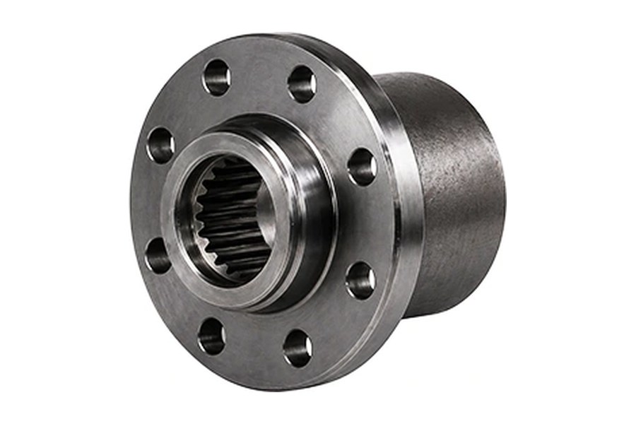
A shaft–hub connection usually loosens because the joint no longer maintains the contact, engagement, or retention needed to carry its actual loads. The immediate symptom may be rotational movement, axial migration, fretting debris, or a fastener that repeatedly loses preload. The underlying cause can lie in the fit, the load history, the component geometry, or the way the assembly was installed.
Finding that cause requires more than tightening the nearest screw. A joint that has moved may already have worn contact surfaces or damaged a keyway. Restoring the original assembly setting does not necessarily restore its capacity. The following investigation sequence helps buyers and maintenance teams decide what evidence to collect, what to measure, and what to change before ordering replacement parts.
Read the first signs before dismantling
Begin by describing the movement precisely. Is the hub turning relative to the shaft, sliding along it, rocking under a reversing load, or showing runout while remaining locked in position? These observations lead to different checks. A radial alignment problem can resemble looseness, while axial movement may involve a missing or ineffective retaining feature even when torque transmission remains adequate.
Record when the symptom appears. Movement during startup suggests a different load event from movement after a long hot operating period. A problem that began after maintenance may point toward seating, lubrication, or component interchange. A problem that developed gradually may involve wear, repeated overloads, or changing alignment elsewhere in the machine.
Before moving anything, photograph the alignment marks, the uncovered portions of the shaft, every retainer, and the positions of neighboring parts. If the equipment can be safely isolated, record accessible movement without forcing the joint further. Do not continue operating a visibly unstable connection merely to collect a longer history; additional damage can erase the evidence that explains the original event.
Preserve the evidence at disassembly
Mark the relative orientation of shaft and hub before separation. Record the removal method and any unusual resistance. A component that releases easily may have lost contact pressure, but easy removal alone does not identify why. Likewise, a difficult removal can result from galling or corrosion rather than a correctly functioning fit.
Collect photographs before cleaning. Polished bands, dark debris, reddish deposits, localized scoring, and contact concentrated near one end can each be useful clues. Fretting is associated with small relative movements at contacting surfaces, but debris color by itself is not enough to diagnose the complete failure mechanism.
Keep the key, screws, washers, retaining rings, and other removed hardware associated with the assembly. Substituting new hardware immediately can conceal a dimensional or seating problem in the original parts. Record any visible thread damage, uneven bearing marks, or deformed key edges before deciding which components are suitable for reuse.
Ask whether the failed pair was supplied together or assembled from separate stock. Replacement forged hubs and shafts may each conform to their individual drawings while the chosen tolerance combination fails to provide the intended joint behavior. Traceability to the actual component revisions is therefore part of the mechanical investigation.
Follow the torque through the joint
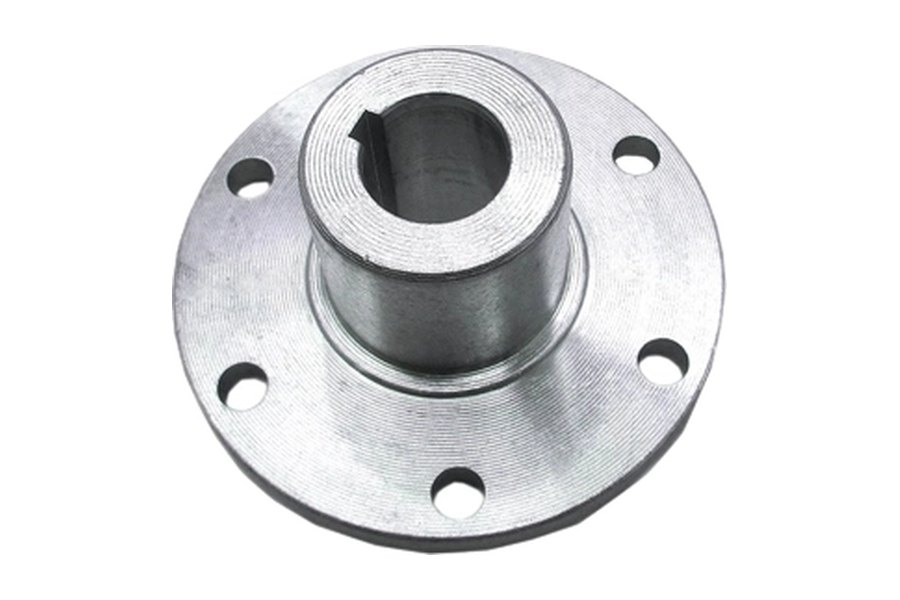
Sketch the load path in plain terms. In a conventional keyed connection, the key and its mating flanks transmit torque through contact forces. In an interference connection, contact pressure and friction over the engaged surface provide resistance to relative movement. In a clamping arrangement, tightening hardware establishes the normal force used by the joint. Some designs combine mechanisms, which makes their intended contributions important.
Do not assume that two torque-transmission mechanisms share load equally. A key may engage only after a small relative displacement, while a friction interface may carry load before that happens. Without an engineering basis for load sharing, simply adding nominal capacities can overstate the capability of the assembled connection.
Separate torque transmission from axial retention. A parallel key generally does not, by itself, establish a complete axial locating system. Shoulders, nuts, rings, end plates, or other specified features may be needed. If the complaint is axial migration, inspect those features directly instead of treating the key as the only relevant component.
Then compare the design duty with the real duty. Repeated reversing torque, starts, emergency stops, jams, overhung loads, and thermal cycles can matter more than the average running torque. A smooth steady load used during selection may not represent the most demanding event that the joint actually experiences.
Separate four routes to lost retention
The initial fit did not provide the intended contact
A nominal diameter is not a fit specification. The shaft and bore limits determine the possible combinations, while taper, roundness, surface condition, and effective contact length affect the assembled interface. A shaft measured once with a micrometer and a bore measured only at its entrance can leave important variation undetected.
Excessive clearance in a keyed assembly can allow movement that repeatedly loads the key edges. Insufficient interference can leave a friction joint short of its required capacity. Excessive interference is not a universal cure either: it can increase assembly damage or overstress the hub. The appropriate limits must come from the geometry, materials, loading, and assembly method.
The applied load exceeded the joint’s working capacity
A connection can move even when every component was manufactured correctly. A process change may introduce larger shock loads, a faster reversal, or a more severe startup. Misalignment or an overhung load can add bending and uneven contact to a joint that was considered mainly as a torque connection.
Look for a credible link between the observed damage and the operating event. One-sided contact or repeated movement at the same orientation can justify a closer alignment review. A single overload followed by continuing movement may have permanently changed the contact surfaces, so returning to the original operating duty may not stop the problem.
The assembly process reduced the designed retention
Burrs, trapped debris, incorrect key height, incomplete shoulder seating, or an unsuitable surface condition can prevent the intended contact from developing. Assembly force should pass through the features designed to receive it. Driving a hub into position through unrelated components can damage them without proving that the shaft–hub interface has seated correctly.
Lubrication requires a defined instruction. It can influence pressing behavior, fastener preload, and the friction available in the finished joint. A lubricant that helps installation may change the assumptions used to calculate torque capacity. Neither universal dry assembly nor universal lubrication is a sound replacement for the specified procedure.
The joint changed after installation
Temperature differences between hub and shaft can change their relative dimensions and contact pressure. Predict the change from the dimensions and thermal behavior of each component at its own operating temperature. A connection assembled successfully at room temperature still needs to be evaluated for its operating and shutdown conditions.
Wear, surface settling, corrosion, and repeated small movements can progressively alter contact. In a clamped design, the hardware and seating surfaces also influence retained preload. A recurring need for retightening is evidence to investigate, not a substitute for understanding why the original preload or contact condition was lost.
Measure the joint as a system
After documenting the surfaces, clean them using a method that does not remove the evidence needed for dimensional assessment. Measure the shaft and bore at several axial positions and orientations. Record actual values rather than only a pass result, especially where taper or localized wear could explain why the joint contacted unevenly.
For a keyed design, check key width, keyway width, engagement length, flank condition, and the specified top clearance. A key that appears snug at one location can still rock or contact poorly over its working length. Verify the shaft and hub keyways as a pair; replacing only the key may leave the damaged load-bearing surfaces unchanged.
For an interference fit, compare the measured size relationship with the design range and review the actual contact length. Include the hub wall section, material condition, and any adjacent slots or reliefs that affect stiffness. A diameter difference cannot be interpreted fully without knowing the structure that must sustain the resulting pressure.
Check the locating faces and adjacent components too. A burr at a shoulder can stop axial seating. A damaged bearing support can alter alignment. Runout at the outside of a hub may reflect the hub geometry, the shaft geometry, the assembly position, or several contributions together. Measure enough of the system to distinguish them.
- Identify the parts: Match the shaft, hub, and retention hardware to the applicable drawing revisions.
- Map the dimensions: Record size and form across the actual engagement region.
- Inspect the load-bearing surfaces: Locate wear, dents, raised material, and incomplete contact.
- Reconstruct assembly: Compare the documented procedure with what was actually done.
- Review operating events: Connect the damage pattern with temperature, torque, and alignment history.
Correct the cause rather than the symptom
If dimensional variation caused inadequate contact, revise the relevant limits and inspection coverage. Do not change the shaft diameter alone without checking the hub stress and assembly implications. When ordering replacement forged shafts, provide the mating bore requirements and the condition in which final measurements must be made.
If overload or reversing duty caused the problem, the engineering response may involve a different connection arrangement, engagement length, shaft section, or operating strategy. These changes require a system review. Making a key larger can reduce remaining material in the shaft or hub and may introduce a different weakness.
If the cause was assembly, convert the successful method into a controlled work instruction. Define cleaning, burr removal, permitted lubrication, alignment, seating confirmation, and the applicable tightening or thermal procedure. An instruction that only says “assemble securely” cannot be audited and is difficult to reproduce across shifts.
Repair methods also need explicit acceptance. Peening a shaft, adding an unapproved retaining compound, or modifying a keyway may change the load path and prevent reliable future removal. Where repair is technically justified, document the revised dimensions, material considerations, inspection, and service limitations instead of treating the repair as invisible.
Prove the repair under representative duty
Where a clamping fastener is involved, distinguish the specified tightening input from the resulting clamp load. Thread condition, bearing surfaces, and lubrication affect that relationship. A torque wrench reading obtained during dismantling is not a direct measurement of the preload that existed during service. Use an appropriate verification method for the connection and retain the original assembly record when it is available.
Check whether the apparent improvement depends on selecting one unusually favorable pair of components. A production solution must work across the approved dimensional range, including replacement parts supplied later. If matched pairs are required, identify and preserve those pairs. If interchangeability is required, the design and tolerance review must cover the relevant combinations rather than only the pair used in the trial.
A successful no-load rotation is only an initial check. Verification should reflect the conditions that previously produced movement, within an approved test plan. That may include controlled starts, reversals, thermal stabilization, and inspection of axial position or relative witness marks. The test should not deliberately exceed the machine’s approved operating limits.
Set the acceptance observations before the test. Decide how relative movement will be detected, which temperatures or vibration measurements are relevant, and when the connection will be inspected again. If the design calls for a post-assembly check, state its timing and method rather than relying on an informal recommendation to “check later.”
Record the final component identities and measured assembly condition. Otherwise, a later successful run cannot be tied confidently to the changes that produced it. A controlled comparison is more useful than replacing several parts and changing several procedures without preserving which differences mattered.
Create a useful failure-review package
The most useful package for a supplier contains the component drawings, actual mating dimensions, photographs before cleaning, assembly instructions, operating history, and a clear description of the movement. Include the required delivery condition and identify whether the order covers a blank, a finished component, or a matched assembly.
Keep observations separate from conclusions. “The hub moved axially after the first hot operating cycle” is an observation. “The bore was machined too large” is a conclusion that needs measurement evidence. This distinction helps the supplier respond with a focused manufacturing review instead of arguing against an unproven diagnosis.
A lasting repair addresses the actual cause of movement. Use the measured fit, load history, and assembly evidence to define the replacement parts and verification checks.