
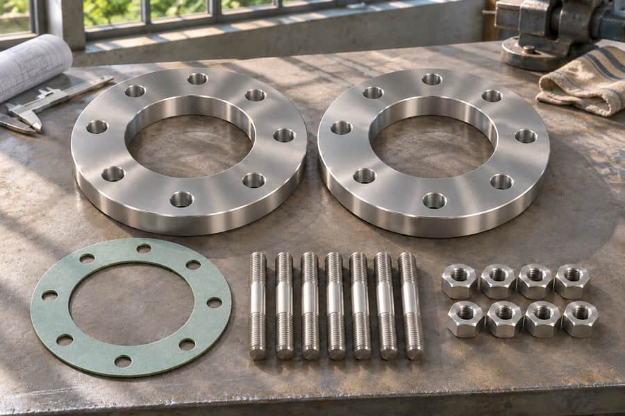
Forged flanges are often selected for high-pressure service because controlled deformation can support material continuity, favorable grain flow, and consistent mechanical properties. These benefits depend on alloy selection, processing, heat treatment, and inspection.
Pressure capacity still comes from the applicable flange specification. Reliable performance also requires correct material specifications, dimensional compliance, joint assembly, gasket selection, and operating-condition evaluation.
What Forging Contributes to a Pressure Connection
High-pressure piping systems place demanding requirements on flange materials and connections. Components must withstand internal pressure while maintaining dimensional stability and supporting the mechanical loads transferred through connected piping and equipment.
Forging offers a manufacturing route that can help meet these requirements. The process applies compressive forces to solid metal, producing controlled plastic deformation that changes its shape and influences its internal structure.
Material Integrity Through Controlled Forging
During forging, a heated billet or other suitable starting material is compressed using a hammer or press. Metal flows under the applied force until it approaches the required component geometry.
This deformation can produce favorable grain flow and a more controlled internal structure than processes involving molten-metal solidification. The resulting characteristics depend on the starting material, deformation conditions, component geometry, and subsequent processing.
For flange applications, these considerations matter because the component contains several functional features. The flange body, hub, bore, bolt holes, and gasket-contacting surface must collectively satisfy the design requirements.
Nevertheless, grain flow should not be treated as proof of product integrity. Improper processing, unsuitable starting material, or inadequate inspection can still result in unacceptable discontinuities or properties.
Mechanical Properties and Manufacturing Consistency
Mechanical properties determine how a flange responds to applied loads. Tensile strength, yield strength, ductility, and toughness must all be considered when evaluating a material for pressure-containing service.
Controlled forging can support consistent material characteristics, but the final properties also depend on the selected grade and heat-treatment condition. Buyers should therefore verify specified mechanical properties rather than assume them from the manufacturing method.
Manufacturing consistency is equally important. Billet selection, forging operations, heat treatment, machining, and inspection need appropriate controls to produce components that meet their specified requirements.
Consider a pump discharge line that cycles between hot operation and shutdown. The flange assessment must address changing bolt load and gasket behavior, as well as the steel properties.
Forged Steel Flanges vs. Cast Steel Flanges for High-Pressure Applications
Forging and casting produce steel components through different manufacturing mechanisms. Understanding these differences helps engineers evaluate suitable production routes without assuming that one process is automatically appropriate for every flange design.
Differences in Manufacturing Processes and Material Structure
Forging shapes solid metal through compressive deformation. The process can influence grain direction and internal structure as the material flows under applied force.
For a casting, the flange profile takes shape as liquid steel freezes within the mold cavity. The resulting structure develops through solidification, which can introduce characteristics different from those associated with wrought or forged products.
Cast steel must also be distinguished from cast iron. Their metallurgy and specification routes differ, so the names cannot be used as substitutes on a purchase order.
The comparison between forged and cast steel flanges concerns two manufacturing routes for steel components, not a comparison between steel and iron.
Neither manufacturing route eliminates the need for process control. Forged products can contain defects, while properly manufactured and inspected cast steel components can satisfy specific engineering requirements.
Comparing the Two Options for Pressure Service
The appropriate choice depends on component geometry, material requirements, production controls, inspection provisions, and applicable design standards. Engineers should compare documented product properties rather than rely on general descriptions of manufacturing advantages.
| Comparison factor | Forged steel flanges | Cast steel flanges |
| Manufacturing method | Solid metal shaped through compressive deformation. | Molten steel poured into a mold and solidified. |
| Internal structure | Deformation influences grain flow and material structure. | Solidification determines the resulting casting structure. |
| Property development | Verified for the chosen alloy after its deformation and thermal-processing route. | Depend on material grade, casting controls, and subsequent processing. |
| Inspection considerations | Require appropriate examination of the forged material and finished component. | Require examination methods appropriate for potential casting discontinuities. |
| Selection considerations | Consider deformation capability, geometry, material requirements, and production controls. | Consider casting feasibility, geometry, material requirements, and production controls. |
Forged flanges are frequently considered when controlled deformation and the mechanical characteristics of forged material suit the application. However, casting may remain appropriate for certain geometries and specified engineering conditions.
For a high-pressure pipeline connection, the buyer should compare the required material properties, applicable product specifications, inspection requirements, and documented acceptance criteria before selecting either route.
Materials Used for High-Pressure Forged Flanges
Material selection should begin with the process medium and operating environment, not simply the highest available strength value. Corrosion resistance, toughness, weldability, temperature exposure, and compatibility with connected components all influence suitability.
Carbon Steel Forged Flanges
Carbon steel is commonly considered for industrial piping systems where its mechanical properties and environmental compatibility satisfy the design requirements. It can be suitable for many pressure-containing applications when the specified grade meets the governing requirements.
Check the pressure design basis alongside the hottest and coldest credible conditions. Then assess whether the fluid or external environment can attack the proposed carbon steel. Weldability and toughness also deserve attention when the flange connects to welded piping.
Replace a broad carbon-steel description with a complete grade designation and the standard covering the forged product. Different grades can have different mechanical-property and processing requirements.
Stainless Steel Forged Flanges
Stainless steel forged flanges are considered when corrosion resistance is an important part of the application. An alloy must be assessed against the chemistry and exposure conditions at that particular connection.
Include cleaning cycles and contaminants in that assessment; the normal process-fluid description may miss the most aggressive exposure. General stainless steel classification does not establish resistance to every corrosive condition.
Engineers should also examine the specified mechanical properties and fabrication requirements. Where welding is involved, the compatibility of the flange material with the adjoining piping and welding procedure needs consideration.
Alloy Steel and Duplex Stainless Steel Forged Flanges
Alloy steel flanges may be selected when the application requires particular mechanical properties or performance under elevated-temperature conditions. Grade selection and heat treatment must follow the applicable material specification.
Duplex stainless steel combines a two-phase metallurgical structure with properties that can be useful in demanding corrosion environments. Some process duties benefit from this combination, particularly where mechanical loading accompanies a demanding corrosion environment.
However, duplex material selection requires attention to the specified grade, metallurgical condition, welding compatibility, and environmental exposure. Review how the material was processed and which examinations demonstrate the specified condition of the supplied forging.
Use this screening table to identify the questions each material family brings to the specification.
| Material family | Typical selection considerations | Important verification points |
| Carbon steel | General industrial pressure-containing service. | Strength, toughness, weldability, and corrosion conditions. |
| Stainless steel | Applications requiring resistance to specific corrosive environments. | Alloy grade, fluid compatibility, and mechanical properties. |
| Alloy steel | Applications requiring particular mechanical or temperature-related properties. | Grade requirements, heat treatment, and mechanical testing. |
| Duplex stainless steel | Selected applications combining strength and corrosion resistance requirements. | Material condition, corrosion compatibility, and welding controls. |
Understanding Pressure Ratings and Standards for Forged Flanges
A forged flange must satisfy the applicable pressure-temperature requirements for its specified material, dimensions, and standard. Its manufacturing route does not independently determine the allowable operating pressure.
What Does an ASME Pressure Class Mean?
ASME flange standards use pressure Class designations to identify standardized pressure-temperature rating categories. A Class designation is not a direct pressure measurement or a pressure value expressed in psi.
The allowable pressure associated with a flange depends on factors including its material group, operating temperature, nominal size, and governing standard.
Therefore, two flanges carrying the same Class designation may have different allowable pressures when their material groups or operating conditions differ.
Engineers should consult the applicable pressure-temperature rating tables instead of converting a Class designation into an assumed pressure value. The selected flange must remain within the rating permitted for its actual specification and service conditions.
ASTM Material Specifications and ASME Flange Standards
ASTM material and product specifications establish requirements for materials and particular product forms. Depending on the specification, these requirements can cover chemical composition, mechanical properties, heat treatment, testing, and product condition.
ASME flange standards address dimensional requirements and pressure-temperature ratings within their defined scope. They provide the framework for determining whether a particular standardized flange configuration is suitable for the specified design conditions.
Material conformity and flange-rating compliance answer separate questions during design review. A flange made from material meeting an ASTM specification does not automatically satisfy every dimensional or pressure-rating requirement of an ASME flange standard.
For procurement, the material specification and flange dimensional standard should both appear clearly in the purchase documentation. Where additional project or piping-code requirements apply, those requirements must also be identified.
Why Forging Does Not Automatically Increase a Flange’s Pressure Rating
Forging can influence material characteristics, but standardized pressure ratings are established through the applicable design and rating framework. A manufacturing process cannot independently authorize a higher rating.
For example, selecting a forged flange instead of another manufacturing route does not permit an engineer to assign a higher pressure Class than the applicable standard allows. The material group, size, temperature, and standard remain controlling considerations.
Where a project uses a nonstandard or specially engineered flange, its design requires the appropriate engineering evaluation. Buyers should not rely on general claims about forging as evidence of additional pressure capacity.
Factors Affecting Forged Flange Joint Performance
Flange performance depends on the assembled connection, not just the properties of the individual flange. Gasket behavior, bolt loading, facing geometry, piping loads, and temperature changes all influence joint integrity.
Flange Facing and Gasket Compatibility
The flange facing provides the contact geometry required for the selected gasket arrangement. Raised-face and ring-type joint configurations are examples of facing options used in different flange designs.
Each arrangement requires compatible gasket dimensions and materials. Engineers should consider the process fluid, pressure, temperature, facing condition, and applicable assembly requirements when specifying the complete joint.
A suitable flange material cannot compensate for an incompatible gasket. Likewise, selecting a gasket without checking the facing dimensions can create assembly problems or an unsuitable sealing arrangement.
Machined face condition also matters. The specified surface finish and geometry should match the applicable standard and gasket manufacturer’s requirements, where relevant to the project.
Establishing the Required Gasket Compression
Tension in the fasteners draws the two flanges together, loading the gasket across its contact area. Appropriate preload helps establish the contact pressure needed for the specified sealing arrangement.
Insufficient preload can reduce gasket compression, while excessive or uneven loading may damage the gasket, overstress fasteners, or distort joint components. Both conditions can affect connection reliability.
Torque is commonly used as an installation control, but the relationship between applied torque and achieved bolt tension depends on several variables. Thread condition, lubrication, fastener properties, tightening sequence, and assembly method all influence the result.
For this reason, a universal bolt-torque value should not be applied to every high-pressure flange connection. The assembly procedure must reflect the specified fasteners, gasket, flange configuration, and engineering requirements.
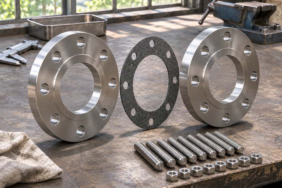
External Loads, Alignment, and Thermal Cycling
Internal pressure is only one source of loading on a flange joint. Connected piping can introduce bending moments, axial forces, torsional effects, and other loads through equipment connections and support arrangements.
Misalignment during installation can add unwanted stress before the system enters service. Engineers should check piping fit-up and support conditions rather than use flange bolts to force incorrectly aligned components together.
Thermal cycling introduces another consideration. Temperature changes can affect flange dimensions, bolt tension, gasket behavior, and the relative movement of connected components.
Repeated heating and cooling may alter joint loading over time. Applications involving frequent startup and shutdown therefore require attention to the complete operating cycle, not just the initial assembly condition.
Manufacturing Quality and Inspection of High-Pressure Forged Flanges
Manufacturing quality determines whether a forged flange conforms to its specified material and dimensional requirements. Buyers should establish inspection expectations before production rather than assume that the word forged represents a complete quality-control system.
Billet Selection, Forging, and Heat Treatment
The manufacturing process begins with suitable starting material. Its identification and conformity with the specified grade should be established before forging operations proceed.
Forging controls need to account for material behavior, deformation, component geometry, and the intended production route. These factors influence the resulting structure and the ability to meet specified product requirements.
The required delivery condition determines the thermal processing needed for the selected alloy. Different material families may require different processing routes, so one general heat-treatment procedure cannot be assumed suitable for every forged flange.
Where mechanical testing is specified, results should be reviewed against the applicable acceptance requirements. Buyers should confirm that the test documentation corresponds to the supplied material and production condition.
Dimensional and Surface Inspection
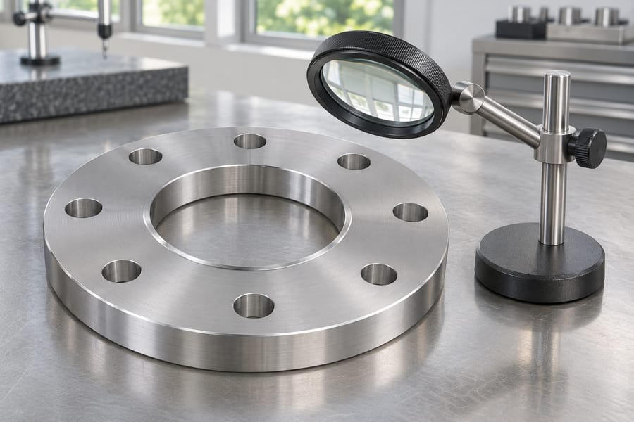
Dimensional inspection verifies whether the finished flange matches the approved drawing and applicable dimensional standard. Important features include outside diameter, thickness, bore, bolt-hole arrangement, bolt-circle dimensions, and facing geometry.
These details affect installation and compatibility with connected piping or equipment. A mismatch in bolt-hole positioning, for example, can prevent proper assembly even when the material itself meets its specification.
Facing inspection should address the contact surface and its specified finish. Machining marks, damage, or dimensional deviations may affect gasket seating and require evaluation against the applicable acceptance criteria.
Non-Destructive Examination and Manufacturing Records
Non-destructive examination can provide additional information about material or product condition without destroying the component. Available methods include ultrasonic testing, magnetic particle testing, and liquid penetrant testing.
These methods do not serve identical purposes. Their suitability depends on material characteristics, examination objectives, product geometry, and the requirements of the governing specification or purchase order.
For example, ultrasonic examination may be specified to assess internal discontinuities, while liquid penetrant examination can help identify surface-breaking indications. Write the examination procedure and rejection limits into the inspection plan before the component is tested.
Documentation provides traceability between the specified requirements and supplied components. Build the document package around the order: link material identity to property tests and thermal records, then include the required dimensional and NDE reports.
Defining the Scope of Pressure Testing
Determine from the project requirements whether a pressure test belongs at the component, assembled-joint, or completed-system stage. The applicable procedure must define the test conditions and acceptance criteria.
Buyers should not assume that every individual flange requires the same pressure test or that one pressure-test multiplier applies universally. Testing requirements may differ between a component, an assembled joint, and a completed piping system.
Inspection plans should identify the responsible parties, required examination stages, documentation, and procedures for handling nonconforming results. These arrangements help prevent disagreements during production approval and final acceptance.
Specifying High-Pressure Forged Flanges from Boberry Machining
When sourcing forged flanges, buyers should provide enough engineering information for the required material, configuration, and machining details to be identified clearly.
The forged flange range from Boberry Machining covers carbon, alloy, stainless and duplex steels, together with a choice of connections and facings.
Available configurations include weld-neck, slip-on, and blind flanges, among other connection types. Custom machining options include bore dimensions, bolt-circle features, and flange-face requirements based on the specified project configuration.
A practical request for quotation should identify the following information:
- Material specification: State the required material grade and applicable ASTM material or product specification.
- Flange standard: Identify the applicable ASME dimensional and pressure-temperature standard or other governing design requirements.
- Nominal size: Provide the required flange size and connection details.
- Pressure and temperature: Specify design conditions, including relevant minimum and maximum temperatures.
- Flange configuration: Identify the required weld-neck, slip-on, blind, or other applicable design.
- Facing requirements: State the facing type and compatible gasket arrangement.
- Machining dimensions: Provide bore, bolt-circle, face, thickness, and other drawing-controlled dimensions.
- Inspection requirements: Identify required mechanical testing, dimensional checks, non-destructive examination, and documentation.
- Acceptance criteria: Reference the governing specifications and any additional project-specific inspection requirements.
For nonstandard configurations, approved drawings should accompany the inquiry. They help clarify dimensional relationships and reduce uncertainty about interfaces, machining allowances, and inspection points.
Buyers should also identify whether additional documentation or examination is mandatory before manufacturing begins. Agreeing on these requirements early helps align the production scope with the actual engineering and procurement needs.