
Metal forging shapes solid metal through compressive force applied by presses, hammers, or dies. Controlled deformation creates defined geometry and can develop favorable internal structures for demanding mechanical parts.
This article explains the process, major methods, suitable materials, benefits, and industrial applications. It also covers manufacturing limitations, inspection requirements, and practical sourcing considerations.
What Is Metal Forging?
In forging, metal is plastically deformed rather than melted and poured into a mold. Sufficient force permanently changes its shape, while temperature, tooling, and deformation sequence determine how material flows.
Forging may begin with bar stock, billets, ingots, or prepared preforms. The resulting component may be close to its final dimensions or may require substantial machining, depending on its geometry and tolerances.
Unlike a casting, a forged part does not acquire its shape through solidification in a mold. However, forging does not automatically eliminate defects or guarantee superior performance; incoming material and process conditions remain critical.
Typical examples include transmission shafts, gear blanks, flanges, hubs, and connecting rods. Engineers select forging when the expected load path, required properties, and production economics support the additional forming operations.
How Does the Metal Forging Process Work?
Although the manufacturing route differs between a large open-die shaft and a small impression-die component, most projects follow a sequence of material preparation, deformation, finishing, and verification.
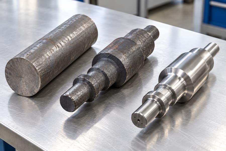
Material Selection and Billet Preparation
Production starts by confirming the alloy, material condition, and starting stock. Billet dimensions must provide enough volume for the finished shape, trimming losses, and any planned machining allowance.
Engineers also examine how the proposed starting geometry will deform. An inappropriate preform can cause uneven filling, unnecessary flash, or local folding even when the alloy is otherwise forgeable.
- Material identity: Verify the specified grade and relevant chemical composition requirements.
- Starting volume: Account for finished mass, process losses, and machining stock.
- Surface condition: Check for defects that could extend or open during deformation.
Heating and Temperature Control
Hot forging heats metal above its recrystallization temperature so it can undergo substantial deformation with manageable force. Actual heating ranges depend on the alloy, section size, and process design.
Excessive heating may promote undesirable grain growth, oxidation, or surface damage. Insufficient heating can increase forming loads and cracking risk, especially where thin sections cool rapidly before filling.
Temperature uniformity matters as much as the initial target. Large cross-sections may heat unevenly, while transfer time between furnace and tooling can change the metal’s behavior during deformation.
Applying Force and Controlling Material Flow
Forging equipment applies compression through repeated blows or a controlled pressing stroke. Die geometry, friction, deformation rate, and workpiece temperature influence the direction and extent of metal flow.
For impression-die components, preforming may distribute material before the finishing cavity is filled. This reduces the chance of underfilled corners, excessive flash, and damaging fold formation.
For large open-die pieces, operators may progressively upset, draw out, or rotate the workpiece. Multiple passes change its cross-section while maintaining sufficient stock for later machining.
Trimming, Heat Treatment, and Machining
Some closed-die forgings produce flash at the die parting line, which must be trimmed. Scale removal and surface cleaning may follow, depending on the process and downstream inspection requirements.
Heat treatment can adjust hardness, strength, toughness, and microstructure. The selected cycle must suit the alloy and finished section size; improperly controlled treatment can produce distortion or inconsistent properties.
Machining establishes precise bores, bearing seats, threads, sealing faces, or gear teeth. Forging allowances should be planned around these functional surfaces rather than added uniformly without regard to the design.
Final Inspection and Release
Inspection checks whether the resulting part meets its drawing and purchase specification. Depending on criticality, this may involve dimensions, mechanical tests, surface examination, and appropriate nondestructive testing.
Inspection timing also matters. Some discontinuities are easier to detect after scale removal or rough machining, while final dimensional inspection should occur after operations likely to change geometry.
Forging Routes: Dies, Geometry, and Working Temperature
Forging Methods Based on Tooling and Geometry
Open-die forging compresses work between dies that do not fully surround it. The process accommodates large or relatively simple shapes, but substantial machining may be needed to establish finished features.
Closed-die forging uses shaped impressions to direct metal into a defined cavity. It is often advantageous for repeat production, although die cost and fill behavior require careful evaluation.
Rolled ring forging expands a pierced workpiece between rotating tools. The method is especially relevant to seamless rings, but it is not an alternative for components with unrelated solid geometries.
| Method | Typical Parts | Engineering Advantage | Key Tradeoff |
| Open-Die Forging | Shafts, discs, blocks | Flexible stock size and forming sequence | Greater machining allowance |
| Closed-Die Forging | Levers, connecting rods, gear blanks | Repeatable shaped preforms | Dedicated dies and filling constraints |
| Rolled Ring Forging | Bearing rings, large rings, flanges | Efficient production of ring geometry | Restricted shape family |
When comparing these methods, assess part size, geometry, expected quantity, and available machining capacity together. BOBERRY’s closed-die forging information is relevant when evaluating an impression-die route for suitable components.
Hot, Warm, and Cold Forging
Temperature classifications describe forming conditions rather than die geometry. Open-die and closed-die methods can involve different working temperatures, so the categories should not be treated as competing lists.
- Hot forging: Supports extensive deformation with relatively lower forming loads, but oxidation and dimensional variation may require greater finishing allowance.
- Warm forging: Balances forming force, surface condition, and dimensional control for suitable alloys and component shapes.
- Cold forging: Can achieve good repeatability and surface finish, but work hardening and high forces restrict feasible shapes and materials.
The appropriate temperature regime depends on forgeability, required deformation, equipment capacity, and final properties. A process that improves dimensional consistency may still be uneconomical if it requires excessive tooling force.
Which Metals Are Suitable for Forging?
Forgeability describes how readily a metal can deform without unacceptable cracking or other defects. It varies with composition, initial microstructure, temperature, deformation rate, and the amount of shape change.
Carbon and Alloy Steels
Carbon steels are widely considered for shafts, fittings, and general mechanical parts. Their suitability depends on the strength and toughness required after forging and any subsequent heat treatment.
Alloy steels offer additional options for hardenability, wear resistance, and demanding load cases. The material specification should define the required condition rather than relying on a broad description such as high-strength steel.
Stainless Steel and Nonferrous Alloys
Stainless steels may be selected where corrosion resistance is important, but different grades have distinct forming and heat-treatment behaviors. Corrosion performance also depends on the environment and surface condition.
Aluminum alloys offer lower density, making them useful where mass matters. Copper alloys may suit electrical or corrosion-related requirements, while titanium alloys require more specialized temperature and process control.
Select the alloy against the conditions the part will encounter, including sustained forces, repeated loading, heat, surrounding media, and rubbing contact. Purchasing an expensive alloy cannot compensate for inappropriate geometry or incomplete quality requirements.
What Are the Benefits of Metal Forging?
Mechanical Performance and Grain Flow
Plastic deformation changes the shape and orientation of the metal’s internal structure. With suitable material quality and processing, this can support desirable combinations of strength, toughness, and fatigue performance.
Grain flow is especially relevant around bends, transitions, and other load-bearing features. However, its benefit depends on how the forged structure aligns with the actual stresses in service.
A forged shaft is not automatically stronger than every machined or cast alternative. Alloy condition, defect population, heat treatment, dimensions, and loading direction must be considered before making a comparison.
Production Repeatability and Material Efficiency
With stable dies and controlled input stock, repeated forging cycles can produce consistent preforms. That consistency may reduce variation in downstream machining, although tool wear still needs monitoring.
Near-net-shape forging can reduce chips and machining time compared with cutting a complex part entirely from solid stock. Savings depend on billet yield, flash, rejected pieces, and required finishing operations.
The strongest economic case often appears when a part’s geometry and production quantity justify tooling. For low-volume orders, simpler forging routes or machining from stock may be more practical.
Suitability for Demanding Service
Properly specified forgings are used for parts exposed to torsion, bending, impact, or repeated loading. Their suitability comes from a complete design-and-manufacturing route, not from the forging operation alone.
For critical applications, engineers should link the expected loading to a material requirement, heat-treatment condition, inspection plan, and acceptance standard. This establishes measurable criteria rather than general claims about durability.
What Are the Limitations of Metal Forging?
Forging imposes practical restrictions on geometry, tooling, and material flow. Thin ribs, deep internal cavities, inaccessible undercuts, and abrupt transitions can be difficult or uneconomical to produce directly.
Closed-die designs must consider draft angles, fillets, parting-line placement, and die access. If metal cannot fill a cavity reliably, additional preforming or a geometry revision may be needed.
Large components are constrained by press capacity, handling arrangements, heating equipment, and achievable deformation. Smaller cold-forged parts may be limited by forming force, tool life, and material work hardening.
- Upfront expense: Dedicated dies and process development may be difficult to justify for short runs.
- Secondary operations: Precision features commonly require machining, drilling, or finishing after forming.
- Defect risk: Poor temperature control or material flow can produce laps, cracks, underfill, or dimensional variation.
These limitations are manageable only when acknowledged early. A technically possible forging route is not necessarily the lowest-risk or lowest-total-cost manufacturing choice for every component.
Metal Forging vs. Casting vs. CNC Machining
Forging changes the shape of solid metal, casting solidifies liquid metal, and CNC machining removes material. Each route offers distinct advantages, and complex mechanical assemblies frequently use more than one.
| Factor | Forging | Casting | CNC Machining |
| How Shape Is Produced | Compressive deformation | Solidification in a mold | Controlled material removal |
| Geometry | Limited by material flow and dies | Can form intricate cavities | Limited by tool access |
| Properties | Influenced by deformation and heat treatment | Influenced by solidification and processing | Depend mainly on starting stock and processing |
| Setup Economics | Die investment varies by method | Pattern or mold investment varies | Usually less dedicated forming tooling |
| Finishing Needs | Often machined at functional surfaces | Often machined at functional surfaces | Produces finished features directly |
For example, a heavily loaded gear blank may justify forging followed by precision tooth machining. A housing with intricate internal passages may be more naturally cast and then machined at mating surfaces.
Those examples illustrate selection logic, not universal rules. Engineers should compare mechanical requirements, feasible geometries, inspection access, tooling expense, lead time, and expected batch size before choosing a route.
Also consider where material is removed. Machining a forged preform may preserve useful grain flow in some regions, but excessive cutting can remove the very geometry-specific benefits that influenced the original choice.
Where Are Forged Metal Parts Used?
Automotive and Transportation Equipment
Crankshafts, connecting rods, transmission components, and some suspension parts experience changing loads. Forging may be selected to develop suitable component geometry and properties, followed by controlled machining and inspection.
Industrial Machinery
Shafts transmit torque, hubs connect rotating elements, and gear blanks form the foundation for precision teeth. Designers assess fatigue resistance, fit, and alignment alongside the required strength of the forged body.
Construction and Agricultural Equipment
Pins, hooks, brackets, and linkage parts can experience shock, wear, and repeated loading. Suitable material treatment and details such as generous transitions often matter as much as the forming method.
Energy and Fluid-Handling Systems
Flanges, rings, valve components, and pressure-containing parts may be forged for specified mechanical or structural requirements. Service involving pressure, temperature, or corrosion demands application-specific material selection and qualification.
Regardless of sector, the same component name may describe very different operating conditions. A flange for a lightly loaded mechanical joint is not interchangeable with one intended for pressure service.
- Rotating equipment: Check runout, balance requirements, and bearing-seat dimensions.
- Structural linkages: Check load direction, stress concentrations, and joint fit.
- Pressure service: Confirm applicable design specifications, material traceability, and inspection scope.
How Is the Quality of Forged Parts Controlled?
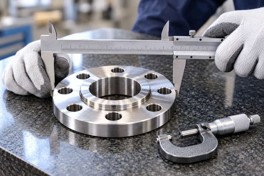
Incoming Material and Process Records
Quality begins with material identification, receiving inspection, and appropriate traceability. A correct final shape cannot compensate for the wrong alloy grade or material condition.
Process documentation may record heating conditions, forging operations, heat-treatment cycles, and significant deviations. For components whose failure could endanger people or equipment, specify which material batches and processing records must remain linked to each delivered item before work begins.
Dimensional and Surface Inspection
Inspection plans should distinguish functional dimensions from noncritical forging surfaces. Bearing seats, bolt circles, sealing faces, and concentric features may need closer control than unmachined external profiles.
Surface examination identifies visible cracks, folds, scale-related damage, and other unacceptable conditions. Inspection after cleaning or rough machining can reveal features that were previously hidden by scale.
Mechanical Testing and Nondestructive Examination
Tensile, hardness, and impact tests provide different information about material behavior. Test location, specimen orientation, sampling frequency, and required acceptance values must be defined for meaningful results.
Ultrasonic testing may examine internal discontinuities; magnetic particle testing suits relevant ferromagnetic materials; liquid penetrant testing can reveal surface-breaking indications on appropriate surfaces.
No single test detects every possible defect. Inspectors must select a method based on material, geometry, likely discontinuity type, and the governing acceptance criteria.
- Before forging: Verify grade, starting dimensions, and specified input documentation.
- After forming: Review shape, trimming condition, and obvious surface defects.
- After treatment: Confirm required material condition and mechanical-test results.
- Before shipment: Verify critical dimensions, examination results, and agreed records.
How to Specify and Source Custom Forged Parts
A successful request for quotation defines what the component must do, not merely its approximate shape. Loading, material condition, dimensions, expected quantity, and inspection requirements all influence process selection.
Send a drawing that separates finished dimensions from acceptable as-forged surfaces. Mark functional datums, machining allowances, radii, and any features whose placement is critical to assembly or service.
- Technical data: Supply drawings, material specifications, required properties, and service conditions.
- Production scope: State quantities, forecast demand, delivery expectations, and whether machining is included.
- Quality documentation: Specify traceability, tests, inspection reports, and acceptance criteria.
- Commercial comparison: Assess tooling, yield, secondary processing, lead time, and inspection together.
Ask potential suppliers to identify forming constraints rather than quoting directly from a finished drawing. An early discussion of parting lines, section changes, or alternative preforms can prevent expensive revisions.
BOBERRY presents custom forged shafts, flanges, hubs, rings, and gears, with open-die and closed-die options and post-machining described in its metal forging services overview. Individual project requirements still need technical review and confirmation.
Before placing an order, agree on deliverable condition, inspection hold points, applicable acceptance requirements, and responsibility for any final machining. These decisions help make supplier quotations comparable and reduce ambiguity at delivery.