
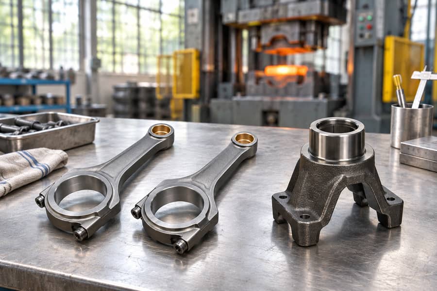
Drop forging is a metal-forming process in which a hammer delivers blows to a workpiece, often heated, to shape it between dies. The blows produce plastic deformation.
For industrial engineers and buyers, the key questions are tooling arrangement, material suitability, achievable geometry, production volume, and finishing needs. These factors determine whether drop forging is appropriate for a component.
What Is Drop Forging?
A drop hammer transfers energy to metal through one or more impacts. Each blow changes the workpiece shape while the material remains solid rather than melting and resolidifying.
In hot forging, the billet is heated to increase formability. The hammer then works against dies that either leave the sides relatively open or contain shaped impressions.
The word drop can describe gravity-driven hammers, but industrial usage also includes power-assisted drop hammers. Equipment design determines how the hammer gains and delivers energy.
Hammer Action and Die Terminology
Hammer forging identifies how force is applied. Open-die and impression-die forging identify how tooling constrains metal flow. These are separate aspects of the process.
An open-die operation can use a hammer, while an impression-die operation can use either hammer equipment or a press. Tooling and force application should therefore be specified separately.
Closed-die forging frequently means impression-die forging in manufacturing discussions. In stricter usage, flashless closed-die forging refers to a substantially enclosed cavity without intentional flash.
For projects involving repeated shaped parts, drop forging services should be evaluated against actual drawings, material requirements, expected quantities, and finishing scope—not the process label alone.
How Does the Drop Forging Process Work?
The manufacturing route begins before the first hammer blow. Material preparation, temperature control, forming sequence, and downstream operations together determine whether a forging meets its drawing.
Material Selection and Billet Preparation
The starting alloy must meet service demands such as loading, wear, corrosion exposure, and operating temperature. Availability and suitability for forging also influence grade selection.
Billets are cut to a volume that accounts for the intended shape, flash where required, and machining stock. Excess material increases waste; insufficient material risks underfilling.
Billet Heating
Hot-forging billets are heated within a suitable range for their alloy. Heating reduces resistance to deformation, making it easier to fill complicated impressions without excessive forming loads.
Temperature must remain controlled throughout handling and forming. Overheating may damage the material or increase scaling, while excessive cooling can impair flow and encourage cracking.
Die Preparation and Billet Positioning
Toolmakers establish the required impressions, allowances, and metal-flow paths. A part may need a preliminary shaping impression before the final cavity can be filled consistently.
The operator or handling system places the heated billet in the correct orientation. Misplacement can cause uneven filling, misalignment, excessive flash, or local damage to tooling.
Hammer Forging and Die Filling
Successive blows push the metal toward the available space. In impression dies, the cavity directs deformation; in open dies, the operator controls positioning and progressive shaping.
A preforming stage can distribute material toward thick sections before finishing blows. Without sufficient stock in those regions, later impacts may not completely fill the final impression.
Conventional impression dies may include a flash land. Metal escaping into this narrow region creates flash and contributes resistance that can help fill the cavity.
Trimming, Cooling, and Heat Treatment
When flash is present, a trimming operation removes it. The forging then follows a cooling route chosen for its material, section size, and required final condition.
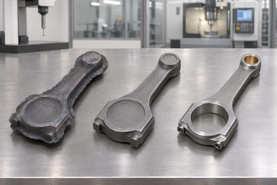
Some alloys and applications require normalizing, annealing, quenching and tempering, solution treatment, or another specified treatment. These are alternatives, not interchangeable finishing steps.
Heat treatment may improve or establish particular properties, but its purpose and sequence must match the alloy. Distortion and subsequent machining allowances deserve attention at this stage.
Cleaning, CNC Machining, and Inspection
Cleaning removes scale and surface contamination so features and surface discontinuities can be assessed. The required finish depends on whether the part remains a forging blank or proceeds to machining.
CNC machining produces controlled bores, faces, threads, and mating dimensions that forging alone may not hold economically. Inspection then checks drawing features and specified acceptance criteria.
What Are the Main Tooling Arrangements Used in Drop Forging?
Die arrangement has a major effect on geometry, material flow, trimming, and required machining. Die geometry and the machine delivering the force are independent choices.
Open-Die Hammer Forging
Relatively simple dies compress stock without completely enclosing it. The metal can spread laterally, and successive blows develop the section through controlled movement and repositioning.
Open-die work suits certain straightforward shapes and preforms, but complex detail usually requires additional operations. It does not inherently offer the same repeatable cavity definition as impression dies.
Impression-Die Drop Forging
Shaped impressions guide the workpiece toward a defined geometry. Multiple impressions can redistribute material before final forming, helping the die fill without severe local deformation.
This arrangement is useful for recurring components with features that justify dedicated tooling. Conventional impressions often produce flash, which must be removed before final processing.
Where Flashless Closed-Die Forging Fits
Flashless forming uses a substantially enclosed cavity and no intentional flash. Because surplus material has little escape path, billet volume and filling behavior need especially close control.
The term closed-die forging is often used broadly for impression-die work. A drawing or process specification should clarify when strictly flashless forming is intended.
| Consideration | Open-die hammer forging | Conventional impression-die forging | Flashless closed-die forming |
| Tooling | Relatively simple, open arrangements | Shaped impressions, potentially multiple stages | Substantially enclosed cavity |
| Metal flow | Directed through successive positioning and blows | Guided toward cavity features | Highly constrained by enclosed volume |
| Flash | No conventional impression flash | Often designed into the process | No intentional flash |
| Suitable work | Simpler sections and preliminary shapes | Repeatable detailed components | Shapes compatible with precise stock control |
| Main tradeoff | More subsequent shaping or machining | Dedicated tooling and trimming | Tight billet-volume and filling requirements |
What Materials Are Commonly Used in Drop Forging?
Material selection begins with a defined grade and required final condition, not simply a broad family name. Different alloys respond differently to heating, deformation, cooling, and treatment.
Carbon Steel and Alloy Steel
Carbon steels can suit general mechanical components where an appropriate balance of strength, ductility, machinability, and cost is required. Carbon content and processing affect the outcome.
Alloy steels offer additional choices for hardenability, toughness, and demanding loading conditions. Selecting an alloy does not itself guarantee performance; section size and subsequent treatment matter.
Stainless Steel
Stainless steel may be selected where corrosion resistance is important alongside mechanical behavior. Different stainless families vary significantly in hot workability, strength, and response to heat treatment.
For example, common austenitic grades cannot be hardened by conventional quench-and-temper treatment in the manner of hardenable martensitic steels. The correct route follows the actual grade.
Aluminum and Other Forging Alloys
Aluminum alloys are considered where mass reduction matters, but forging temperatures, die behavior, and heat-treatment options depend on the alloy series and temper requirements.
Certain titanium and copper-based alloys can also be forged for specialized service conditions. Their processing demands should be assessed individually rather than extrapolated from familiar steel practice.
Where Drop Forging Helps—and Where It Adds Work
A useful assessment connects each claimed benefit to the specific part and production route. A hammer-forged label alone does not establish superior strength, accuracy, or economy.
Advantages of Drop Forging
- Directed deformation: Appropriate die design can develop grain flow that follows portions of the finished shape, potentially benefiting load-bearing features.
- Mechanical properties: Suitable alloy processing and heat treatment can produce useful strength, toughness, and fatigue behavior, subject to actual acceptance requirements.
- Repeatability: Dedicated impressions support consistent component shapes when billet control, die condition, and forming practice are maintained.
- Reduced stock removal: A near-net-shape blank may require less machining than a component cut entirely from oversized solid stock.
- Downstream flexibility: Forged blanks can be cleaned, heat-treated where appropriate, and CNC-machined to meet functional dimensions and surface needs.
The benefits depend on successful die filling and process control. Forging does not eliminate inclusions, cracks, or other defects, and some designs gain little from dedicated tooling.
Limitations of Drop Forging
- Initial tooling: Impression dies require design work, production, maintenance, and possible revision when the part geometry changes.
- Shape constraints: Thin walls, inaccessible recesses, and features that oppose die separation may require redesign or machining.
- Finishing requirements: Tight bores, threads, and precision interfaces commonly need CNC operations after forging.
- Material losses: Flash, trimming, scale, and machining allowances can offset some near-net-shape savings.
- Process sensitivity: Temperature, stock volume, die alignment, and impact sequence can contribute to variation or defects.
For low quantities or frequently changing designs, tooling expense may outweigh savings in machining time. For repeated compatible parts, that balance can shift.
What Are the Common Applications of Drop Forging?
Drop forging is considered for parts whose geometry, loading, material, and production requirements fit hammer forming. The following components are examples of candidates, not claims that every version is drop forged.
Automotive and Transportation Components
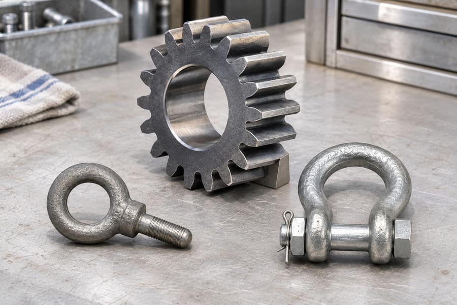
Connecting rods, drivetrain yokes, and selected gear blanks may be made by suitable impression-die forging routes. Their critical surfaces generally require subsequent machining and inspection.
A forged gear blank does not emerge with finished tooth accuracy simply because it was formed in a die. Tooth generation, bores, heat treatment, and final checks depend on design.
For such projects, forged gears are best specified by material, blank geometry, intended tooth-forming operations, and the finished acceptance requirements.
Industrial Machinery Components
Hooks, linkage components, and industrial brackets may benefit from shaped forgings when their load paths and production quantities justify tooling. Other processes may suit alternative designs.
A hook’s curved region, for example, presents a different metal-flow challenge from a flat bracket. Local section transitions and service loading influence die design and inspection priorities.
Construction and Agricultural Equipment Components
Load-bearing connectors, impact-exposed hardware, and equipment supports can be evaluated for forging. Abrasion, shock loading, corrosion, and repair requirements affect material and finishing choices.
Custom Engineering Components
Custom forged blanks are often intermediate products. A near-net-shape form can preserve machining stock around critical features while reducing unnecessary material removal elsewhere.
Whether that route is worthwhile depends on production quantity, die feasibility, alloy supply, and the total work required to reach an accepted finished component.
How Does Drop Forging Compare With Other Manufacturing Processes?
Process comparisons are meaningful only when they use the same material requirements, component function, and final acceptance conditions. Otherwise, differences may come from design rather than manufacturing method.
Drop Forging vs. Press Forging
Hammer forging transfers energy through impacts; press forging develops deformation through a press stroke. The force-time profile and material response differ, but both can use open or impression dies.
Press operation may suit certain deformation and control requirements; hammer operation may suit others. Neither force-application label proves better strength, dimensional accuracy, or cost on its own.
Drop Forging vs. Casting and CNC Machining
Casting forms a component as molten metal solidifies. It can offer geometric options that are difficult to forge, but its solidification-related defect risks differ from forging defects.
CNC machining removes stock instead of deforming it. It is useful for precision features and design flexibility, although machining a complex part from solid stock can generate substantial waste.
| Factor | Drop forging | Press forging | Casting | CNC machining from stock |
| Principle | Impact deformation of solid metal | Press-applied deformation of solid metal | Solidification of molten metal | Material removal |
| Shape control | Die geometry and hammer sequence | Die geometry and press stroke | Mold or pattern geometry | Toolpaths and tool access |
| Investment emphasis | Hammer tooling and setup | Press tooling and setup | Mold, pattern, and casting preparation | Programming, fixtures, and cutting time |
| Material consideration | Flash and finishing allowances may apply | Allowances depend on die route | Gates, risers, and machining stock vary by method | Removed stock becomes chips |
| Best evaluated by | Formability, volume, features | Load, stroke, volume, features | Castability and defect acceptance | Tolerance, access, and quantity |
A sensible comparison includes finished-part machining, inspection, scrap exposure, and tooling allocation. A low blank cost can be misleading if substantial downstream work remains.
What Affects Drop Forging Quality, and How Should Buyers Select a Process?
Quality depends on the entire route, not only the forming stroke. Drawings, material records, process controls, and inspection criteria must correspond to the intended service conditions.
Common Defects and Quality Controls
- Underfilling: A cavity remains incompletely filled because of stock distribution, temperature, die design, or forming conditions.
- Laps and folds: Unfavorable metal flow creates surface discontinuities that may remain after trimming or cleaning.
- Cracking: Unsuitable forming temperatures, material condition, or deformation can initiate cracks during production.
- Die mismatch: Incorrect die alignment produces offsets or unwanted changes in component geometry.
- Dimensional variation: Die wear, thermal changes, and cooling behavior can affect repeatability and machining allowances.
Appropriate controls include material identification, billet inspection, temperature monitoring, die maintenance, and checks at relevant production stages. No single inspection method detects every defect.
Visual and dimensional inspection may be adequate for some features. Where service demands justify it, buyers can specify mechanical testing or suitable nondestructive examination with clear acceptance limits.
Key Considerations When Selecting Drop Forging
Geometry is the first filter. Parting direction, section transitions, draft, and access for later machining affect whether an impression can form the required blank economically.
Material requirements are equally specific. An alloy grade, required heat-treatment condition, and measurable property criteria are more useful than an unsupported request for a “strong forging.”
Quantity changes the decision. Die costs are spread across accepted parts, while trimming, machining, and inspection continue to affect the cost of each completed component.
Buyers should also check whether a near-net-shape forging leaves sensible material for final machining. Excess allowance wastes time; too little can leave surfaces uncleaned or dimensions unachievable.
Preparing a Component Brief for Boberry Machining
A useful technical inquiry should connect the drawing to the intended manufacturing route rather than requesting a process name without the information needed to assess feasibility.
- Engineering drawing: Provide geometry, tolerances, surface requirements, and critical functional features.
- Material specification: State the grade, applicable standard, and required final condition.
- Expected quantity: Identify anticipated batch sizes and whether repeat production is likely.
- Downstream scope: Distinguish as-forged features from those requiring heat treatment, cleaning, or CNC machining.
- Quality acceptance: Define dimensional checks, testing, documentation, and any required nondestructive examination.
Boberry Machining can use these requirements to discuss billet preparation, die shaping, trimming, optional grade-appropriate heat treatment, cleaning, and CNC finishing within a suitable manufacturing plan.
The decisive question is whether that complete route delivers the specified accepted component with workable tooling, material use, inspection, and production economics—not whether its name sounds preferable.