
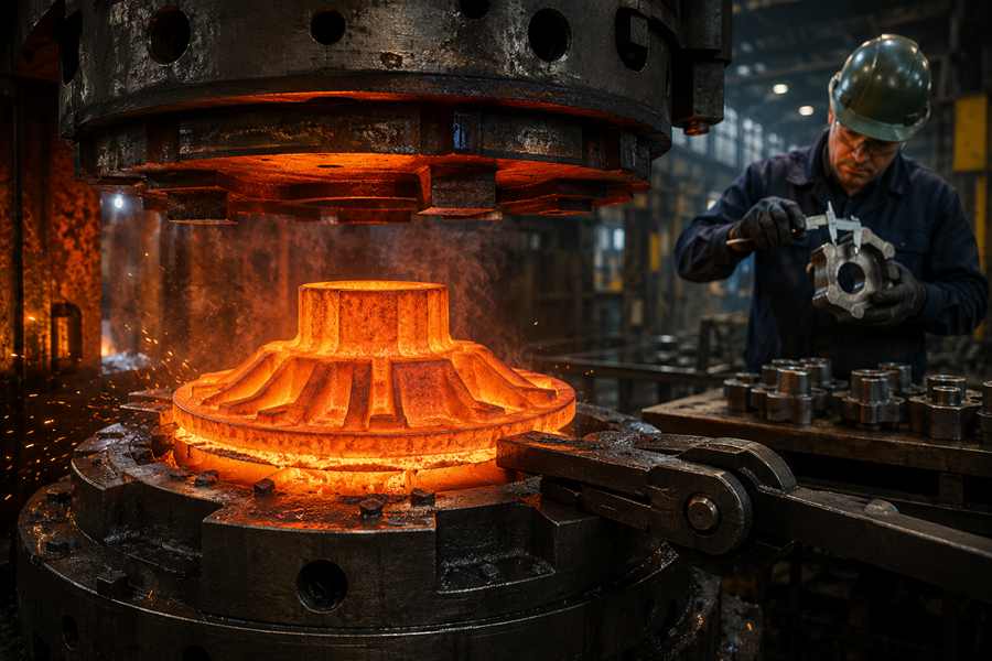
A forging parting line is the boundary where the upper and lower dies separate after forming. Its location affects cavity filling, flash removal, dimensional control, machining stock, surface quality, and tooling design.
What Is a Forging Parting Line?
A forging parting line forms where two die sections meet during closed-die forging. As the heated billet fills the cavity, surplus metal is pushed through the narrow gap near this boundary and forms flash.
After forming, most flash is removed with a trimming die. A shallow ridge, trimmed edge, or small mismatch may still remain on the rough component.
The parting line is closely related to:
- Die-opening direction
- Cavity shape
- Metal-flow path
- Flash location
- Trimming access
- Forging release
- Machining allowance
The most suitable line is not necessarily the least visible one. In my view, stable forming and easy die release should come before appearance, provided the final surface requirements are still met.
Key Features of a Forging Parting Line
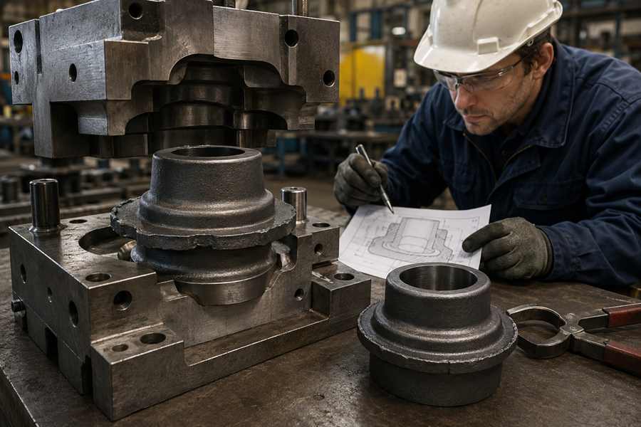
Die Separation Boundary
The line follows the surface where the die halves open. On simple and symmetrical forgings, it often runs around the widest external profile.
Irregular parts may need an offset, curved, or stepped separation surface. This helps the component leave the cavity without becoming trapped.
Connection with the Flash Zone
Extra metal usually escapes through the gap beside the separation line. The resulting flash creates resistance, which helps build pressure inside the cavity.
Flash design influences:
- Billet volume
- Cavity pressure
- Filling performance
- Trimming force
- Material utilization
Too little flash may weaken cavity filling, while excessive flash increases material and processing costs.
Visible Surface Mark
Trimming removes the main flash, but it may leave a narrow ridge or slight edge difference. Die wear and poor alignment can make this mark more noticeable.
The line may be acceptable on hidden or machined areas. Decorative and hand-contact surfaces often need grinding, polishing, or tighter mismatch control.
Early Tooling Decision
The separation route is selected before the forging dies are manufactured. Changing it after tooling approval may require substantial modification or a completely new die set.
Buyers should confirm the following information early:
- Critical dimensions
- Visible surfaces
- Machining datums
- Unmachined areas
- Acceptable mismatch
- Surface-finishing requirements
Early confirmation reduces the risk of costly changes after sample production.
Advantages of a Well-Placed Parting Line
Balanced Cavity Filling
A suitable location helps the heated material enter both die halves evenly. This is particularly useful for parts containing ribs, hubs, bosses, arms, and changing cross-sections.
Better distribution reduces the risk of:
- Incomplete filling
- Folds
- Laps
- Cold shuts
- Local pressure peaks
It also makes dimensions more consistent across repeat batches.
Easier Forging Release
The parting surface works together with draft angles to release the component from the cavity. A practical route prevents deep features from locking inside one die half.
Clean removal shortens handling time and reduces surface damage. It also lowers the extraction force applied to the tooling.
Simpler Flash Removal
An accessible edge allows the trimming die to reach the entire flash profile. This reduces manual grinding and improves edge consistency.
The benefit becomes more valuable in high-volume projects. Even a small reduction in finishing time can noticeably lower the cost per component.
Improved Machining Control
A properly located line stays away from bearing seats, sealing faces, threads, and precision bores whenever possible. Machining allowance can then be distributed more evenly.
This supports:
- Stable clamping
- Clear machining datums
- Lower stock removal
- Shorter cutting time
- More predictable wall thickness
Buyers receive a rough forging that is easier to process into the finished component.
Limitations of a Forging Parting Line
Residual Ridge and Mismatch
A trimmed edge may still leave a raised line or a small step between the two die halves. Tool wear, die movement, and trimming variation can increase this difference.
Minor marks can often be removed during machining. Unmachined or visible areas may need additional finishing.
Additional Billet Material
Flash formation requires more starting material than the finished component contains. Longer and more complicated separation routes usually generate more excess metal.
That extra material must be:
- Heated
- Forged
- Trimmed
- Transported
- Recycled
The cost impact is more noticeable on large parts and expensive alloy grades.
Secondary Trimming Work
Complex lines need more complicated trimming tools. Narrow corners or changing edge heights may also require local grinding.
Manual correction raises labor costs and can create inconsistent edge quality. Buyers should confirm whether trimming and grinding are included in the quoted price.
Potential Dimensional Offset
If the upper and lower dies do not align correctly, one side of the forging may shift relative to the other. The resulting offset appears directly along the separation boundary.
Small deviations may be removed during machining. Larger offsets can reduce wall thickness, disturb feature positions, or push the part outside tolerance.
Why Does the Position of a Forging Parting Line Matter?
The selected location defines how the component is divided between the upper and lower dies. It affects tooling structure, metal distribution, dimensional references, production cost, and compatibility with the finished design.
Die Structure and Cavity Balance
The chosen route determines the depth and geometry of each die cavity. A balanced division normally simplifies tooling and avoids unnecessarily deep sections.
Offset or stepped routes may be required for uneven shapes. The final choice should follow the component geometry rather than visual symmetry alone.
Material Distribution During Forming
The separation surface changes how heated metal moves into ribs, flanges, hubs, bosses, and recessed areas. A suitable route allows the material to enter both cavity halves more evenly.
Balanced flow supports complete filling and stable feature formation. It may also reduce the extra billet volume needed to fill difficult sections.
Dimensional References for Machining
The meeting point between the dies is also an area where dimensional variation may occur. Its position therefore affects tolerance planning, inspection, and machining allowance.
It should remain away from:
- Precision bores
- Bearing seats
- Sealing faces
- Threads
- Assembly contacts
When crossing a machined surface cannot be avoided, the supplier may need to leave additional stock.
Flash Length and Production Cost
The route controls the length, shape, and accessibility of the flash edge. These factors influence billet weight, trimming-tool complexity, finishing time, and overall material use.
| Parting-Line Position | Production Effect | Typical Cost Impact |
| Widest outer profile | Simple opening and easy trimming | Lower tooling and finishing cost |
| Central flat plane | Balanced upper and lower cavities | Stable cost for basic geometries |
| Offset surface | Matches unequal part geometry | Moderate tooling complexity |
| Stepped or curved route | Supports multi-level features | Higher die and trimming cost |
| Hidden edge or underside | Reduces visual exposure | May complicate cavity design |
For repeat orders, reducing flash weight or trimming time can lower the unit price. Tooling cost should therefore be reviewed together with expected production efficiency.
Link to Finished-Part Requirements
The line must support forging release while remaining compatible with machining, assembly, and surface expectations. It connects the rough-forging layout directly with the final use of the component.
This connection is the main reason its position matters. A well-planned route simplifies forming without shifting unnecessary work into later operations.
Factors to Consider When Positioning the Parting Line
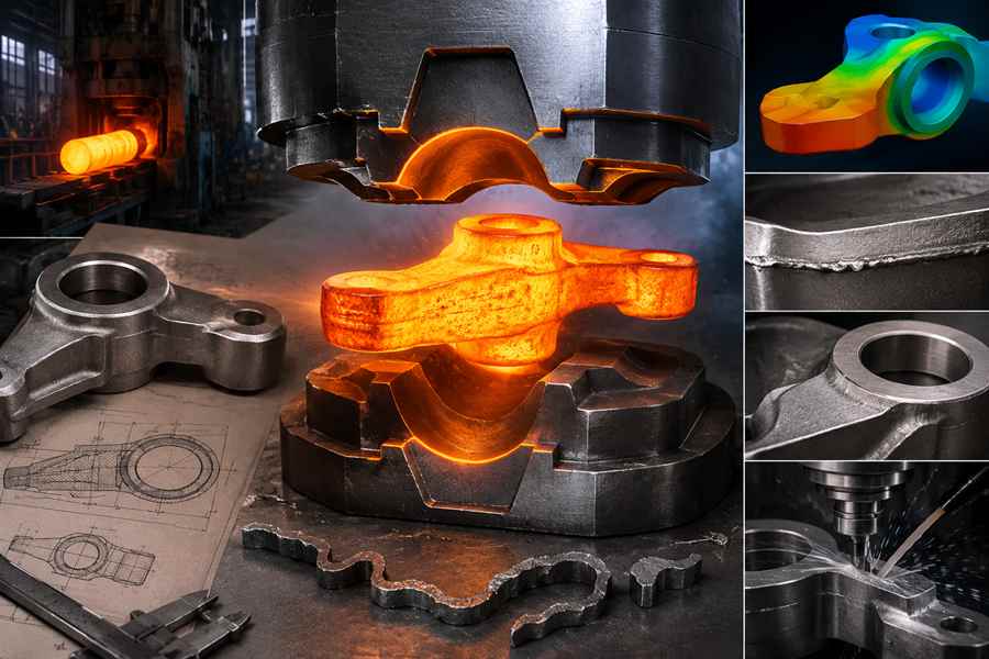
Component Geometry
Simple shapes usually allow a flat separation surface near the largest cross-section. Uneven or multi-level parts may require a curved, stepped, or offset design.
The route should remain as straightforward as the geometry permits. Unnecessary complexity increases die-manufacturing and trimming expenses.
Functional Surface Locations
Critical surfaces need stable dimensions and clean finishes. The parting line should avoid them whenever the geometry allows.
Important areas include:
- Sealing faces
- Precision holes
- Bearing locations
- Threaded features
- Mounting surfaces
- Assembly contacts
Marking these features clearly helps the die designer avoid creating extra machining work.
Metal Flow and Draft
The line should support smooth movement into thick and thin sections while allowing the forging to leave the dies. Deep cavities and near-vertical walls may restrict the available position.
Adding more draft can simplify removal but also increases machining stock. The design should balance die release with finished dimensions.
Machining Datum and Allowance
The forging supplier needs to understand how the component will be clamped and located during machining. A reliable datum helps maintain balanced stock around the part.
The purchase drawing should specify:
- Finished dimensions
- Rough-forged dimensions
- Machining datums
- Minimum wall thickness
- Concentricity limits
- Straightness requirements
- Acceptable die mismatch
These details connect the forging design with the final cutting process.
Appearance, Volume, and Cost
Visible components may require the line to be placed on an underside, natural edge, or recessed area. Hidden industrial parts usually allow greater flexibility.
For prototypes, simple tooling with additional machining may offer better value. For repeat production, a more optimized die layout can reduce variation, flash weight, and unit cost.
The Best Position Supports the Complete Production Route
A suitable forging parting line should make forming, trimming, machining, and inspection work together:
- Metal fills the cavity evenly
- The component releases cleanly
- Critical surfaces avoid likely mismatch
- Flash remains easy to remove
- Machining stock stays balanced
- Visible areas meet appearance requirements
- Repeat batches maintain similar dimensions
A visually simple route may produce difficult metal flow, while a slightly curved line may improve filling and reduce later machining. Its position should be judged by the complete manufacturing result rather than appearance alone.
Before tooling approval, buyers should review the proposed line, flash area, machining datums, and visible surfaces with the supplier. This early step helps prevent die changes and improves production consistency.