
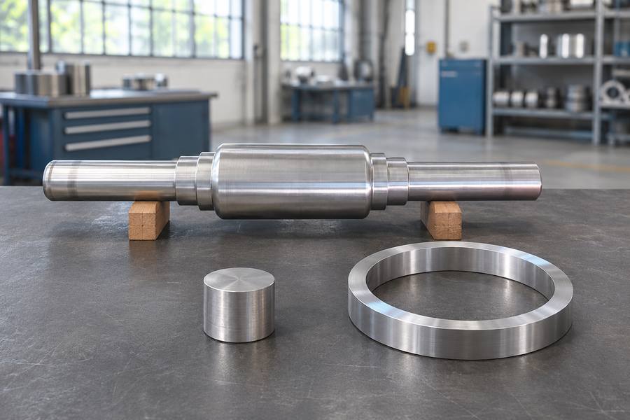
Roll forging names a specific longitudinal process or a broader family of forming methods, depending on context. Tool movement, material flow, and suitable component shapes distinguish these operations.
Narrowly, it usually means longitudinal roll forging; broadly, it can include cross wedge, helical, and ring rolling. Rotary forging is related but distinct.
What Does Roll Forging Mean?
The term roll forging is not used with one universal scope across technical discussions. Some references reserve it for longitudinal deformation between grooved rolls; others use it informally for multiple rolling-based forging operations.
Ask how the tools and billet move before interpreting a supplier’s process name. Tool motion, workpiece motion, contact pattern, and resulting geometry provide a more reliable classification.
Narrow and Broad Definitions
In the narrow definition, longitudinal roll forging passes a heated billet between rotating rolls containing shaped grooves. The rolls progressively reduce selected sections and redistribute material along the workpiece.
The broader definition may include cross wedge rolling, helical rolling, and ring rolling because their tooling progressively deforms the workpiece. However, these processes have distinct contact arrangements and material-flow patterns.
Rotary or orbital forging belongs in a related category, not automatically within longitudinal roll forging. Its die moves through an inclined or precessing path, deforming a localized region rather than drawing stock through grooved rolls.
A useful overview of roll forging should explain the operating mechanism before comparing applications. The umbrella term does not mean that every process uses interchangeable equipment or tooling.
Main Types of Roll-Based Forming Processes
Longitudinal Roll Forging
Longitudinal roll forging uses two or more rotating rolls with profiled grooves to reduce and shape a heated workpiece. The billet advances through the roll gap as the grooves engage successive sections.
The rolls rotate in opposite directions at the working gap, drawing the material into the tooling. Their profiles control where metal is compressed, displaced, and redistributed along the workpiece.
The process commonly develops stepped or tapered sections from a relatively uniform starting billet. A shaft blank, for example, may receive reduced end sections while retaining a larger central body.
Depending on the groove sequence, the workpiece can undergo several reductions or shaping passes. Each pass needs a suitable transition so material fills the intended profile without abrupt flow conditions.
Typical applications include elongated components with changing cross-sections, such as axles, connecting elements, and selected forged shafts
. The process is relevant when repeated shaft-like geometries justify dedicated roll tooling.
Key engineering considerations include:
- Groove design and pass sequence: Determine material movement between larger and smaller sections.
- Billet dimensions and temperature: Influence deformation resistance and groove filling.
- Transition radii and section changes: Affect local strain and the risk of laps or underfilled regions.
- Roll alignment and machining allowance: Influence shape consistency and final dimensional control.
Longitudinal roll forging is not automatically suitable for every long component. Complex branches, transverse features, deep recesses, or irregular sections may require another forming route or substantial machining.
After forging, critical diameters, shoulders, grooves, and bearing seats may still require machining, followed by dimensional inspection against the drawing.
Cross Wedge Rolling
Cross wedge rolling uses wedge-shaped tools to reduce selected billet sections while causing the workpiece to rotate and elongate. The wedge profile controls the progression of deformation along the billet.
The tooling may use opposed flat dies or rotating rolls, depending on the machine arrangement. In either case, wedge geometry creates a controlled reduction zone rather than longitudinal grooved passes.
As the wedges engage, the billet rotates around its axis while material moves axially. Local diameter reductions produce corresponding changes in cross-section and length, often forming several stepped regions in one sequence.
A stepped shaft blank illustrates the process well. Different wedge sections can create reduced ends, intermediate shoulders, and larger journals, provided the geometry suits the tool path and material flow.
Cross wedge rolling is often considered for rotationally symmetrical components produced in repeated quantities. It can reduce machining stock and material waste in suitable designs, but results depend on geometry and process control.
Important design considerations include:
- Wedge angle and profile: Influence deformation progression and axial material movement.
- Billet diameter and length: Affect stability and available material for each section.
- Tool symmetry and alignment: Help control billet rotation and balanced forming.
- Transition and end design: Influence material flow, excess stock, trimming, and machining needs.
Cross wedge rolling should not be confused with longitudinal roll forging merely because both use moving tooling. Their tool profiles, workpiece kinematics, and deformation sequences are fundamentally different.
Features that interrupt rotational symmetry, require transverse branches, or demand complex local details can make cross wedge rolling unsuitable for that component.
Helical Rolling
Helical rolling, often discussed alongside skew rolling, uses rolls whose axes are inclined relative to the workpiece axis. This arrangement causes the billet to rotate while advancing through the forming zone.
The rolls contact the workpiece along a moving, generally helical path. Their combined rotation and inclination create continuous deformation, unlike discrete groove engagement in longitudinal roll forging.
The process is used for rotationally symmetrical products such as steel balls and bearing rollers. Depending on tooling and production route, it can form repeated components from continuously fed bar or billet.
Key process considerations include:
- Roll inclination and groove geometry: Determine rotation, axial advance, and final shape.
- Billet feed and temperature: Influence continuity and deformation consistency.
- Material separation and end formation: Affect the geometry of individual pieces.
- Surface condition and final dimensions: Require evaluation after forming and any subsequent heat treatment or machining.
Helical rolling is not simply another name for cross wedge rolling. Both may combine billet rotation with axial movement, but their tooling geometry and intended deformation paths differ.
Cross wedge rolling typically uses wedge profiles to create localized reductions and stepped sections. Helical rolling relies on skewed roll contact to sustain a helical progression through the forming zone.
Ring Rolling
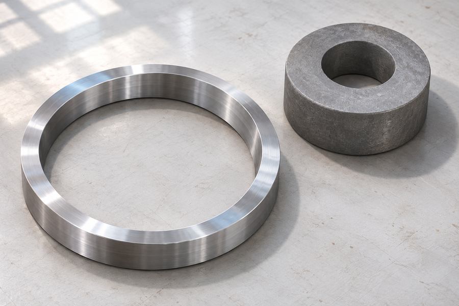
Ring rolling forms a ring-shaped blank by compressing it between a driven roll and a mandrel. As the ring rotates, its wall thickness decreases and its diameter expands.
In radial ring rolling, the main deformation reduces radial wall thickness. The expanding ring retains its annular form, while its inner and outer diameters increase as material flows circumferentially.
Radial-axial ring rolling adds axial rolls that control ring height while radial deformation changes wall thickness. This arrangement is useful when both radial section and axial dimension require coordinated forming.
Typical products include bearing rings, flanges, industrial rings, and other annular components. The process can produce large-diameter rings without machining the entire shape from a solid block.
Important engineering considerations include:
- Starting ring dimensions: Determine material available for expansion and height control.
- Radial and axial reduction: Influence wall thickness, ring height, and dimensional development.
- Roll and mandrel geometry: Affect contact, stability, and final cross-section.
- Ring temperature, material behavior, and inspection locations: Influence deformation consistency and dimensional acceptance.
Ring rolling differs from longitudinal roll forging because the workpiece rotates as an annular blank while its diameter grows. It does not advance through successive longitudinal grooves as a shaft billet does.
For buyers evaluating ring forging, drawings should identify the ring profile, finished dimensions, machining stock, and inspection datums. These details help determine process suitability and remaining finishing requirements.
Rotary Forging and Orbital Forging: Related but Different Processes
Rotary forging is a terminology-sensitive expression because manufacturers and technical references may use it for different rotary forming arrangements. In this section, it refers specifically to orbital or incremental die forging.
Orbital forging uses an inclined or precessing upper die that contacts only part of the workpiece surface during each forming cycle. The contact area moves progressively as the die rotates around its axis.
Unlike conventional forging, where opposing dies may compress a broad area simultaneously, orbital forging concentrates deformation within a localized contact zone. Repeated die movement gradually forms the required geometry.
The lower die generally supports the workpiece while the upper die follows an inclined path. This arrangement creates progressive compression, allowing material to move incrementally rather than experiencing full-area compression at once.
Working Principle and Material Flow
The inclined upper die applies pressure to a limited portion of the component. As the die precesses, the deformation zone travels across the surface and progressively reduces the workpiece.
This localized contact can reduce the forming force required for certain geometries compared with simultaneous full-surface compression. However, actual force requirements depend on material, contact conditions, component dimensions, and process design.
Orbital forging is particularly relevant to relatively compact components with rotational symmetry or accessible forming surfaces. Discs, hubs, flanges, and selected shaped blanks may be considered when their geometry suits incremental die contact.
Typical applications include:
- Disc-shaped components: Localized compression can develop thickness and surface geometry.
- Hubs and flanges: The process may form selected features around a central axis.
- Automotive and mechanical components: Suitable geometries can benefit from progressive deformation.
- Precision-shaped blanks: Incremental contact can support controlled material redistribution before finishing.
How Rotary Forging Differs from Roll-Based Processes
The main distinction is the forming tool and its contact pattern. Longitudinal roll forging uses rotating grooved rolls, while orbital forging uses an inclined die with localized contact.
Cross wedge rolling creates axial elongation through wedge-shaped tooling. Helical rolling uses skewed rolls to produce combined rotation and axial movement, whereas orbital forging progressively compresses selected surface regions.
Ring rolling also differs because its primary purpose is expanding an annular workpiece while reducing its wall thickness. Orbital forging does not rely on this ring-expansion mechanism.
The term rotary forging should therefore not be used as a universal synonym for longitudinal roll forging. When reviewing technical descriptions or supplier proposals, buyers should confirm the actual die movement and workpiece deformation.
Comparison of Different Roll-Based Forming Processes
Although these processes share certain characteristics, their differences become clearer when comparing workpiece movement, tooling arrangement, and material flow.
The following table separates the four roll-based processes from rotary or orbital forging. This distinction prevents unrelated forming mechanisms from being grouped under one narrow technical definition.
| Process | Tool and workpiece movement | Main deformation mechanism | Typical component geometry |
| Longitudinal roll forging | Opposing rolls rotate as the billet advances longitudinally | Progressive reduction through grooved rolls | Stepped shafts and elongated sections |
| Cross wedge rolling | Wedge-shaped tools engage a rotating billet | Localized reduction with axial elongation | Stepped, rotationally symmetrical parts |
| Helical rolling | Inclined rolls rotate and advance the workpiece | Continuous deformation along a helical contact path | Balls, rollers, and rotational products |
| Ring rolling | Ring rotates between driven rolls and a mandrel | Wall-thickness reduction and diameter expansion | Annular rings and flanges |
| Rotary/orbital forging | An inclined die precesses against a supported workpiece | Localized incremental compression | Discs, hubs, and selected flanges |
Understanding the Main Process Differences
Longitudinal roll forging is generally associated with elongated billets requiring progressive section changes. Its tooling creates a sequence of reductions along the workpiece length.
Cross wedge rolling is more suitable for repeated rotationally symmetrical profiles with several diameter transitions. Its wedge arrangement produces axial material movement while shaping individual sections.
Helical rolling serves a different purpose when continuous rotation and axial feed are needed. Its skewed tooling supports products such as balls and rollers rather than conventional stepped shaft profiles.
Ring rolling focuses on annular geometry and controlled expansion. It is particularly relevant when a component requires a larger diameter without removing substantial material from a solid billet.
Orbital forging belongs outside the strict roll-based classification. Its localized die movement makes it a separate forming option for components whose surfaces can be progressively compressed.
Matching the Forming Route to the Drawing
Selecting a suitable process requires more than matching a component name with a manufacturing method. Engineers should evaluate geometry, material behavior, production requirements, finishing operations, and inspection needs together.
A process that produces the required general shape may still be unsuitable when critical features cannot be formed consistently. Manufacturing feasibility must therefore be assessed against the complete component drawing.
Evaluate Component Geometry First
Geometry is usually the most practical starting point because each process has a characteristic deformation pattern.
- Long stepped shafts: Consider longitudinal roll forging when the component has repeated diameter changes along its length.
- Rotationally symmetrical stepped parts: Evaluate cross wedge rolling when wedge tooling can develop the required profile.
- Balls and bearing rollers: Consider helical rolling when continuous rotary and axial forming suits the product.
- Large annular components: Evaluate ring rolling when controlled diameter expansion and wall-thickness reduction are required.
- Discs, hubs, and selected flanges: Consider orbital forging when localized incremental compression can produce the necessary shape.
Geometric complexity also affects tooling feasibility. Deep recesses, transverse holes, branches, undercuts, and sharply changing sections may require secondary machining or a different manufacturing route.
Consider Material and Deformation Characteristics
Material selection influences forming resistance, temperature requirements, and the amount of deformation achievable during each operation. Different alloy families also respond differently to repeated deformation and cooling.
Engineers should review the specified material grade, billet condition, section dimensions, and relevant material requirements before selecting the process. A suitable route must account for the actual material rather than assuming all steels behave identically.
The starting billet must also provide sufficient material for the intended geometry. Inadequate stock can cause incomplete filling, while excessive stock may increase machining requirements and material consumption.
Match Production Requirements with Tooling
Production volume influences whether dedicated tooling investment is practical. Processes using specialized rolls or wedge profiles require tooling development that should be evaluated against expected repeat orders.
For repeated components, dedicated tooling may support consistent production once the forming sequence is established. For smaller quantities or frequently changing geometries, tooling complexity and setup requirements deserve closer consideration.
However, production volume alone should not determine the process. Component dimensions, material utilization, forming feasibility, and downstream operations can outweigh the apparent advantages of a particular production method.
Review Dimensional Accuracy and Finishing Requirements
Forged or rolled dimensions should not automatically be treated as finished machining dimensions. Critical surfaces may require additional machining to meet the drawing requirements.
The engineering review should distinguish between as-formed dimensions, machining allowances, and final acceptance dimensions. This prevents disagreements about whether a supplier is responsible for producing a near-net shape or a finished component.
Important points to clarify include:
- Critical diameters, lengths, wall thicknesses, and shoulder positions.
- Machining allowances on functional and reference surfaces.
- Required surface condition and acceptable imperfections.
- Heat-treatment condition and its influence on dimensional stability.
- Inspection datums and measurement locations.
- Final dimensional and material acceptance requirements.
Heat treatment may change dimensions through thermal expansion, transformation, or distortion. Where final machining follows heat treatment, the manufacturing sequence should preserve enough stock for correction.
Engineering and Purchasing Considerations
Once a possible forming route has been identified, buyers should provide sufficient technical information for a meaningful manufacturing assessment. A component name or approximate sketch alone rarely defines the complete production requirements.
Prepare a Complete Technical Drawing
The drawing should identify the component’s overall geometry, material, critical dimensions, and required manufacturing condition. Section views are particularly useful for showing internal features and changing cross-sections.
For shafts, buyers should identify journal diameters, shoulder locations, grooves, and functional interfaces. For rings, the drawing should specify inner diameter, outer diameter, height, and cross-sectional profile.
Three-dimensional models can supplement engineering drawings when the component contains complex transitions. However, the model should not replace clearly defined dimensional requirements and inspection references.
Specify the Alloy and Delivery State
Name the alloy and its governing specification in the purchase documents. Where relevant, buyers should also specify the required delivery condition, heat treatment, and mechanical property acceptance criteria.
If material substitutions are permitted, the purchasing documents should define the approval procedure. Similar grade designations do not automatically establish identical chemical composition or mechanical performance.
Define Inspection and Documentation Requirements
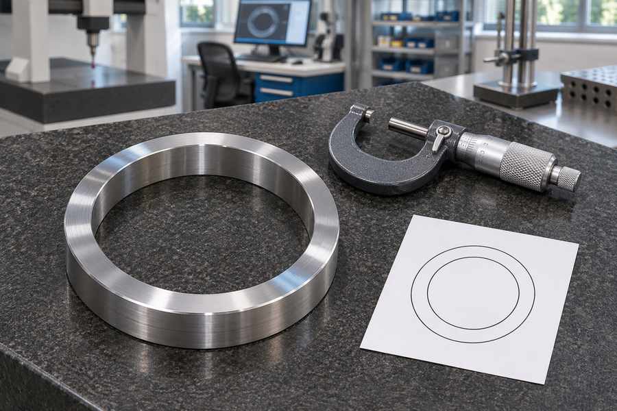
Inspection planning should reflect the component’s functional characteristics and potential manufacturing risks. Different geometries require different measurement arrangements and inspection coverage.
For example, a long shaft may need dimensional checks at several axial positions, while a ring requires measurements around its circumference. The measurement method should account for the component’s support and orientation.
Buyers should also identify which documentation is required at delivery. List the evidence needed with the shipment: traceable material records, the thermal-processing history, measured dimensions, and results of any examinations specified in the order.
Buyer Decision Checkpoints
| Purchasing checkpoint | Information to provide | Why it matters |
| Component geometry | Complete drawing, sections, and 3D model where available | Establishes whether the forming route is geometrically feasible |
| Material requirements | Grade, standard, and delivery condition | Determines material suitability and processing considerations |
| Starting dimensions | Billet or blank requirements, where specified | Supports material planning and forming evaluation |
| Production quantity | Initial order and anticipated repeat requirements | Helps assess tooling investment and production planning |
| Dimensional requirements | Critical dimensions, tolerances, and datums | Defines machining and inspection responsibilities |
| Surface requirements | Functional surfaces and acceptable surface conditions | Identifies finishing and inspection needs |
| Heat treatment | Required condition and mechanical property criteria | Establishes the necessary downstream processing |
| Quality documentation | Certificates, inspection reports, and agreed examinations | Clarifies delivery evidence and acceptance responsibilities |
| Final delivery condition | As-forged, machined, or otherwise finished condition | Prevents misunderstandings about the supplied component |
Confirm the Manufacturing Route Before Ordering
A supplier’s proposed process should be evaluated against the actual drawing rather than accepted solely because it carries a familiar process name. Buyers should request clarification when the terminology does not identify the forming mechanism.
The review should establish which features will be formed directly, which require machining, and where inspection will verify dimensional compliance. These decisions also help clarify the responsibility for tooling, intermediate operations, and final acceptance.
When several processes appear technically possible, compare their complete manufacturing routes rather than evaluating forming alone. The preferred route should satisfy geometry, material, production quantity, finishing requirements, and documented quality expectations.