
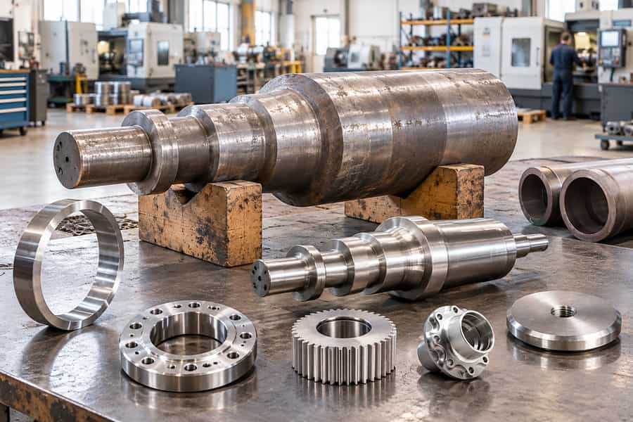
Open-die forging leaves metal free to spread between tools; closed-die forging directs it through shaped cavities. Precision forging describes a dimensional objective: bringing selected features closer to their finished sizes.
Choosing among these approaches requires weighing geometry, alloy, production demand, remaining machining, and tooling investment against the delivered part’s requirements.
How Forging Processes Are Classified
Forging is a bulk-forming process in which compressive force causes metal to deform plastically into a required shape. The process can establish useful grain flow and improve structural integrity, depending on the material, deformation conditions, and subsequent heat treatment.
Open-die and closed-die forging are primarily distinguished by how the dies constrain the workpiece. Precision forging describes an approach focused on closer as-forged dimensions and reduced material removal, often using closed dies and tighter process controls.
Die Configuration and Forming Accuracy
In open-die forging, the workpiece is compressed between dies that do not completely surround it. The workpiece is moved and repositioned between strokes to achieve the required dimensions. Closed-die forging confines material within shaped cavities that guide metal flow into specific features.
Precision forging aims to produce components close to their final dimensions, reducing the stock left for machining where the geometry and process allow. It is not necessarily a separate die arrangement: precision forging often uses closed dies, while conventional closed-die forging may deliberately leave additional machining allowance.
Temperature and Production Conditions
Hot, warm, and cold forging describe the workpiece temperature during deformation. These categories can overlap with open-die, closed-die, and precision forging. Temperature affects flow stress, ductility, oxidation, forming loads, dimensional change, and the ability of metal to fill a die cavity.
Consequently, choosing a forging method requires evaluating both the die arrangement and the material’s forming behavior. The process name alone cannot establish achievable tolerances, mechanical properties, or finished-part cost.
Open-Die Forging: Process, Advantages, and Applications
How Open-Die Forging Works
Open-die forging shapes metal between relatively simple dies without enclosing the workpiece in a complete cavity. The workpiece can spread laterally, so its dimensions are controlled through die movement, stroke sequence, positioning, and equipment or operator control.
Common operations include upsetting to increase a section’s cross-sectional area, drawing out to lengthen stock, and cogging to reduce a large billet in stages. Depending on the design, punching or piercing may also create openings before further forging or machining establishes the final geometry.
Because the workpiece can be repositioned during forming, open-die forging accommodates a broad range of sizes and shapes without requiring a dedicated cavity for every component. The deformation sequence must provide sufficient working throughout the required sections while avoiding folds, uneven dimensions, and excessive temperature loss.
Advantages of Open-Die Forging
- Flexible tooling: Relatively simple dies can accommodate different dimensions, making design changes less dependent on replacing complex tooling.
- Large workpieces: The process can suit substantial shafts, blocks, discs, and other components that may be difficult to handle in smaller closed-die systems.
- Lower dedicated tooling commitment: For custom components and low-volume production, avoiding a full component-shaped die can reduce initial tooling expenditure.
- Controlled deformation: A planned sequence can distribute deformation through the workpiece and help establish grain flow appropriate to the component’s intended loading.
Limitations and Typical Applications
Open-die forgings generally have less geometric detail and lower as-forged dimensional accuracy than components formed in well-controlled shaped cavities. Machining is often necessary to produce bearing seats, keyways, sealing surfaces, holes, and other features requiring precise dimensions.
Multiple forming passes and repeated handling can also influence processing time and consistency. Complex contours may be difficult or impractical to form directly, so the manufacturing plan should identify which features will be forged and which will be machined afterward.
Typical applications include large or custom shafts, cylindrical blanks, discs, rings, blocks, and heavy-duty flanges. These components often benefit from flexible sizing and do not always require intricate features to be formed directly during forging. Suitability still depends on component dimensions, material, equipment, and required mechanical properties.
For a process-specific overview, see BOBERRY’s open-die forging page. When evaluating a component, confirm the proposed forging dimensions, machining allowance, material condition, and inspection plan rather than assuming that the process alone guarantees a particular result.
Closed-Die Forging: Process, Advantages, and Applications
How Closed-Die Forging Works
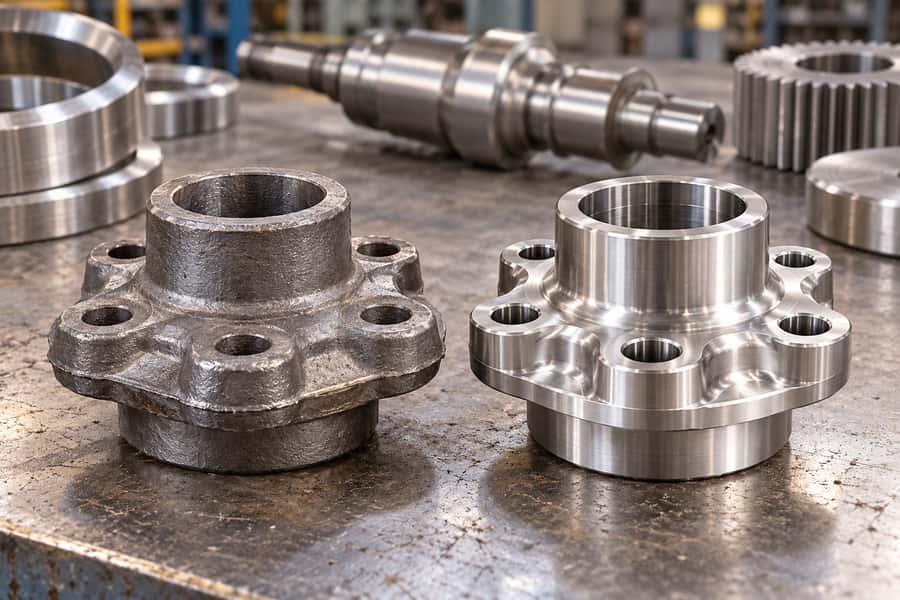
Closed-die forging uses shaped die cavities to direct metal into a defined geometry. A billet is prepared and, for hot forging, heated to a suitable forming range. Depending on the part, preliminary forming stages distribute material before the final cavity establishes the main features.
After forging, excess flash may be trimmed from the parting line when the process uses flash. Flash can help generate pressure that encourages cavity filling, but it consumes material and requires an additional removal operation. Flashless forging is possible for suitable designs, although it demands close control of billet volume, alignment, and process conditions.
Die design must account for material flow, draft angles, fillets, parting-line location, dimensional changes, and the risk of underfilling or folds. A feature that appears straightforward on a drawing may be difficult to fill if metal cannot flow into it without excessive forming loads.
Advantages of Closed-Die Forging
- Shape complexity: Shaped cavities can form contours, ribs, bosses, and other external features that are difficult to produce directly through open-die forging.
- Repeatability: Once tooling and process conditions are established, the cavity provides a consistent geometric reference across production runs.
- Potential machining reduction: Features can be formed closer to their intended geometry, limiting the material removed during finishing.
- Grain-flow control: Suitable die design and deformation can guide metal flow along important contours rather than requiring all geometry to be machined from solid stock.
Limitations and Typical Applications
Closed-die forging requires dedicated tooling, engineering time, and sufficient process control. Tooling investment can be difficult to justify for very small quantities or designs likely to change frequently. Die wear, flash formation, scale, and variations in billet temperature or volume can affect cavity filling and dimensional consistency.
Common applications include connecting rods, hubs, gear blanks, levers, industrial fittings, and other shaped load-bearing components. The method is often attractive when the same geometry will be produced repeatedly and the design benefits from features formed during forging.
However, complex internal passages and enclosed cavities may be difficult to form through conventional closed-die forging. Such geometries may favor casting or a combination of manufacturing methods, depending on the material, structural requirements, and finishing plan.
BOBERRY’s closed-die forging page provides a process-specific starting point for evaluating this manufacturing route. Before selecting it, review the parting line, draft requirements, flash allowance, expected machining, and production quantity with the supplier.
Precision Forging: Higher Accuracy and Near-Net-Shape Production
What Precision Forging Means
Precision forging aims to produce components with closer as-forged dimensions and less excess material than conventional forgings designed for extensive machining. Depending on the component and its requirements, the result may be described as near-net-shape or net-shape production.
Near-net-shape components still require selected finishing operations. Net-shape production is appropriate only when the required geometry can be achieved without additional material removal on the relevant features. Neither term automatically means that every surface meets its final functional tolerance directly after forging.
Precision forging commonly relies on accurately manufactured dies and carefully controlled process conditions. It is best understood as an accuracy and process-control objective rather than a completely separate die configuration. Many applications use closed dies, but not every closed-die forging qualifies as precision forging.
How Precision Forging Achieves Higher Accuracy
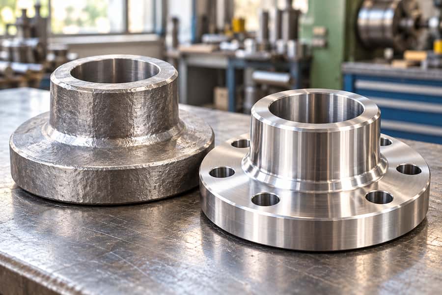
Billet volume is important because insufficient material can leave a cavity underfilled, while excessive material can increase flash, forming loads, or die stress. Billet weight, dimensions, and preparation must therefore remain consistent with the cavity design and intended metal flow.
Temperature control also matters. Material that is too cold may resist deformation and fail to fill details, while excessive or uneven heating can affect oxidation, grain growth, surface condition, and dimensional consistency. Die temperature, lubrication, alignment, and wear introduce additional variables during production.
Designers should distinguish critical dimensions from features that can remain as-forged. Tight tolerances on every surface may increase tooling complexity without delivering a meaningful functional benefit. Specifying tolerances according to assembly and performance needs allows the manufacturing process to focus on the features that matter most.
Advantages and Limitations of Precision Forging
- Reduced material removal: Suitable geometries can be formed closer to final dimensions, reducing unnecessary machining stock.
- Potential cycle-time savings: Less machining may reduce downstream processing time when the forged features meet the required specifications.
- Material utilization: Near-net-shape production can reduce material removed as chips compared with manufacturing the same geometry from a larger blank.
- Higher tooling demands: Accurate dies, consistent billet preparation, and stable process conditions require careful engineering and maintenance.
- Limited geometric freedom: Features that cannot be filled reliably or released from the die may still require redesign or secondary machining.
Precision forging is often considered for gear preforms, transmission components, mechanical connectors, industrial hardware, and other parts where selected dimensions or contours can be formed accurately. Its value depends on whether the reduction in finishing work justifies the additional tooling and process-control requirements.
Before selecting precision forging, identify the dimensions that must be achieved directly after forming, the features that require machining, and the inspection method used to verify both. This assessment helps establish realistic expectations for dimensional capability and total manufacturing cost.
Open-Die vs. Closed-Die vs. Precision Forging
The three approaches differ most clearly in die configuration, geometric freedom, tooling requirements, and the amount of finishing expected. The following comparison provides a preliminary guide; actual performance depends on component design, material, equipment, and production controls.
| Comparison factor | Open-die forging | Closed-die forging | Precision forging |
| Die configuration | Open or partially constraining dies | Shaped die cavities | High-accuracy tooling, often closed dies |
| Typical geometry | Large or relatively simple shapes | Complex external contours | Near-net-shape features where feasible |
| As-forged accuracy | Generally lower | Moderate to high, depending on design | Designed for closer dimensional control |
| Tooling investment | Relatively low for suitable parts | Higher due to dedicated dies | Often higher due to accuracy requirements |
| Production suitability | Custom and lower-volume work, among other uses | Repeated production of shaped parts | Dependent on volume and finishing savings |
| Machining needs | Often substantial | May be reduced | Potentially reduced further on suitable features |
| Main consideration | Size and flexibility | Shape repeatability and tooling economics | Accuracy, process stability, and finishing cost |
Differences in Geometry and Dimensional Accuracy
Open-die forging allows relatively flexible shaping but generally requires more machining to achieve detailed geometries. Closed-die forging uses cavity surfaces to establish more features during forming, while precision forging places greater emphasis on controlling dimensions close to the final specification.
As-forged dimensions must not be confused with finished machining tolerances. A component may leave the forging operation with sufficient stock for machining even when its overall shape is highly repeatable. Conversely, a near-net-shape forging may still need machining on bearing surfaces, holes, sealing faces, or other critical features.
Differences in Production Efficiency
Open-die forging can avoid substantial dedicated tooling expenditure, but repeated forming and downstream machining may increase the cost of each finished component. Closed-die forging spreads tooling investment across production quantities and can reduce the number of operations needed to create complex shapes.
Precision forging may reduce material removal and finishing time, but the benefit depends on the actual geometry and required tolerances. The most accurate process is not automatically the most economical if its tooling and control requirements exceed the savings achieved downstream.
Key Engineering Factors Affecting Forging Quality
Material Selection and Forgeability
Material selection influences deformation behavior, attainable geometry, heat-treatment requirements, and final mechanical properties. Carbon steel, alloy steel, stainless steel, aluminum alloys, and other forgeable materials differ in flow stress, ductility, suitable forming temperatures, and sensitivity to oxidation or cracking.
Engineers should confirm that the selected grade can be forged within the required forming range without unacceptable cracking or excessive forming loads. Material specifications should also define the required heat treatment and mechanical properties, since the forging operation alone does not establish the final condition of the component.
Grain Flow and Mechanical Properties
Plastic deformation changes the metal’s internal structure and can orient grain flow along the shape of the forging. When the process is designed appropriately, this orientation may benefit components subjected to directional loading, such as shafts and connecting rods.
The mechanical advantage of grain orientation varies according to the direction and magnitude of the forces acting on the component during operation. A component with abrupt section changes, poorly formed transitions, or unfavorable loading directions may still experience stress concentrations or fatigue damage. Engineers should assess geometry, load direction, material properties, and the intended deformation sequence together.
Heat treatment can further influence strength, hardness, toughness, and dimensional stability. Where specified, the manufacturing plan should identify the required heat-treatment condition and the tests used to verify it. Neither open-die nor closed-die forging automatically guarantees superior mechanical performance without appropriate material selection and process control.
Dimensional Allowances and Part Design
Forging drawings should distinguish the as-forged profile from the final machined geometry. Machining allowances provide sufficient material to remove scale, correct dimensional variation, and achieve functional surfaces. Allowances that are too small can make finishing difficult, while excessive allowances increase material removal and machining time.
Draft angles, fillet radii, parting-line placement, and section transitions influence how readily metal fills the die and how easily the component can be released. Abrupt changes in thickness may create uneven material flow or localized forming difficulties. Early design review can identify features that should be simplified, forged differently, or completed through machining.
Dimensional verification should focus on the datums and features that control assembly or performance. Engineers should also consider distortion during cooling, heat treatment, and material removal, particularly when the finished part has asymmetric geometry or tight alignment requirements.
Common Forging Defects and Inspection Requirements
Inspection planning should reflect the component’s geometry, material, manufacturing route, and consequences of failure. Potential defects include underfilling, laps, folds, surface cracks, internal discontinuities, and dimensional distortion. Their causes and appropriate detection methods differ, so one inspection method cannot reliably address every risk.
- Underfilling: Check critical contours and cavity details to confirm that the required geometry has formed completely.
- Laps and folds: Review section transitions and areas where metal flow may cause material to overlap rather than consolidate properly.
- Surface cracks: Use visual examination and, where specified, suitable surface nondestructive testing.
- Internal discontinuities: Determine whether ultrasonic or other appropriate examination is required by the component specification.
- Dimensional variation: Measure critical dimensions, alignment features, and machining allowances against the approved drawing.
Acceptance criteria should be established before production rather than improvised after inspection. Material traceability, heat-treatment records, dimensional reports, and nondestructive testing results may be required according to the application and purchasing specification.
How to Choose the Right Forging Process for Your Project
Evaluate Component Requirements First
Begin with the finished component rather than choosing a process based only on its initial purchase price. Identify the part’s dimensions, weight, geometry, material grade, operating loads, required mechanical properties, critical tolerances, and expected production quantity.
Next, determine which features must be formed during forging and which can be produced through machining. A large shaft with straightforward geometry may suit open-die forging, whereas a repeated component with detailed external contours may justify closed-die tooling. Precision forging deserves consideration when reduced machining could offset its additional process-control and tooling requirements.
The following guide provides initial candidates rather than universal rules. Final selection requires confirmation that the process can produce the specified geometry and satisfy the applicable quality requirements.
| Component requirement | Initial process candidate | Reason for consideration | Key check before selection |
| Large custom shaft | Open-die forging | Flexible shaping of substantial sections | Machining allowance and required material properties |
| Low-volume forged blank | Open-die forging | May avoid dedicated complex tooling | Processing time and finishing cost |
| Repeated component with complex external contours | Closed-die forging | Shaped cavities establish repeatable features | Die investment and cavity filling |
| High-volume shaped component | Closed-die forging | Tooling expenditure can be distributed across production | Production consistency and die life |
| Near-net-shape component | Precision forging | May reduce material removal and finishing operations | Achievable as-forged dimensions and remaining machining needs |
| Component with critical functional surfaces | Forging followed by machining, as required | Combines forged geometry with controlled finished surfaces | Datum strategy, machining stock, and inspection criteria |
Compare Total Manufacturing Cost
The total cost of a finished forging includes more than the forming operation. Buyers should account for raw material, billet preparation, tooling, forging, flash removal, heat treatment, machining, inspection, and any required rework. These costs can shift the preferred process substantially.
For low-volume orders, a process with modest tooling requirements may be economical even if it leaves more material for machining. For repeated production, dedicated dies may become more attractive when their cost is offset by shorter downstream operations and consistent geometry. Precision forging is justified only when its achievable reductions in material removal and finishing effort outweigh its additional requirements.
Requesting a quotation based on the finished drawing, annual demand, material specification, and inspection requirements makes comparisons more meaningful. Comparing forging prices without accounting for machining and finishing can produce a misleading result.
When Should Forging Be Considered Instead of Casting or Machining?
Forging vs. Casting
Forging shapes solid metal through plastic deformation, whereas casting forms a component by pouring or introducing molten material into a mold and allowing it to solidify. Forging may be preferable when the required geometry, material, and loading conditions benefit from controlled deformation and suitable grain flow.
Casting can be more practical for intricate shapes, complex internal passages, or geometries that would require extensive forging operations and machining. Cast components have their own process-specific risks, including porosity, shrinkage, and incomplete filling. The appropriate choice depends on the design, material specification, expected loads, production volume, and quality requirements.
Forging vs. Machining From Solid Stock
Machining a component from solid stock offers geometric flexibility and can be useful for prototypes or small quantities. However, producing a large or complex component entirely through material removal may generate substantial scrap. Forging can establish the main geometry first, leaving machining to create precise features and functional surfaces.
For some parts, a hybrid route offers the most practical balance: forge the main shape, apply the required heat treatment, and machine the features that control assembly or performance. The decision should reflect total manufacturing effort rather than an assumption that one process is always superior.
What to Provide When Requesting Custom Forged Parts From BOBERRY
Prepare a Complete Technical RFQ
BOBERRY’s public product information covers custom forged shafts, flanges, hubs, rings, and gears, as well as open-die and closed-die forging and post-machining. Whether a particular component is suitable for a given route should be confirmed against its drawing and technical requirements.
To support an accurate manufacturing assessment, include the following information in the request for quotation:
- Technical drawings: Supply the current drawing revision, complete dimensions, geometric tolerances, and relevant datum references.
- Material specification: Identify the required grade, applicable material standard, and final material condition.
- Service requirements: Describe operating loads, temperature conditions, environmental exposure, and other factors affecting material selection.
- Production quantity: State the initial order quantity and estimated annual demand so tooling economics can be evaluated.
- Machining requirements: Identify critical surfaces, holes, bearing seats, sealing faces, and other features requiring finishing.
- Quality documentation: Specify required material traceability, dimensional reports, mechanical testing, heat-treatment records, and nondestructive examination where applicable.
Confirm Feasibility Before Approving Production
Ask the supplier to review the proposed forging route, die arrangement, machining allowance, and critical dimensions before tooling or production begins. This review should identify features that may be difficult to fill, release, inspect, or finish using the proposed process.
Where dimensional accuracy is especially important, agree on which characteristics will be verified after forging and which will be measured after machining. The inspection plan should also identify applicable acceptance criteria and documentation requirements.
For BOBERRY projects, the manufacturing route and achievable dimensions should be confirmed for the specific component rather than inferred from a general process description. A clearly defined drawing, material specification, production quantity, and quality plan provides a sound basis for evaluating open-die forging, closed-die forging, and precision-oriented manufacturing against the finished part’s actual requirements.