
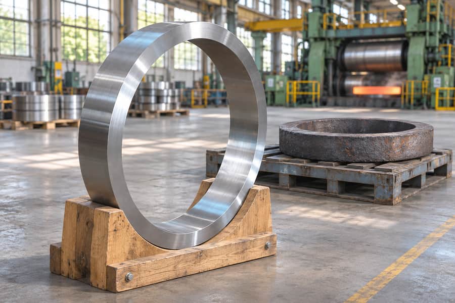
Seamless rolled ring forging turns a hot billet into an annular component by upsetting, piercing, and rolling. Radial reduction enlarges the ring; axial rolls regulate its height.
Billet planning sets the starting stock. Subsequent temperature control, heat treatment, machining, and inspection must bring the material condition and geometry into line with the agreed drawing.
Production Planning and Billet/Preform Design
Engineers begin with the finished drawing, reviewing diameters, height, section profile, material grade, and delivery condition before selecting billet dimensions and the forming sequence.
For custom forged rolled rings, the review also distinguishes plain from profiled sections and identifies surfaces that will remain forged or receive machining. Datums, machining scope, heat treatment, and inspection locations should be clear before production planning is finalized.
Material and Drawing Requirements
Grade chemistry, hot-workability, hardenability, and section response influence heating, deformation, cooling, and heat treatment. Steel and aluminum therefore require separate process plans.
Geometry also affects the route. Steps, shoulders, or changes in radial and axial thickness influence preform distribution, roll contact, and machining stock.
Billet and Preform Planning
The billet must contain enough usable material for the ring and its finishing allowance. Engineers estimate finished-part volume, then account for scale, trimming, machining, and other process losses. The estimate must reflect the selected preform route rather than rely on finished dimensions alone.
Billet diameter, length, and mass are selected to suit upsetting and piercing. Too little material can leave the ring short of its required wall or height; excess material increases deformation demands and waste.
The preform should place material where the final section requires it. Its bore, outside diameter, wall thickness, and height determine the reductions needed during rolling. Poor distribution can make one region grow faster than another, leaving uneven wall thickness or insufficient machining stock.
| Planning input | Decision to make | Failure the decision helps prevent |
| Material grade | Select compatible forming and heat-treatment routes | Unsuitable deformation or final properties |
| Finished dimensions | Calculate billet volume and preform proportions | Insufficient stock or excessive waste |
| Section profile | Plan material distribution and roll contact | Incomplete profile or excess machining |
| Machined surfaces | Allocate stock and establish datums | Unachievable finished dimensions |
The review should distinguish dimensions controlled during forging from those established by machining. Boberry can use the drawing and agreed specifications to define the intended route for ring forging services, rather than treating every finished dimension as a direct rolling target.
Billet Heating and Transfer
Heating must prepare the full billet section for deformation, not merely bring its surface to condition. Operators follow grade- and section-specific requirements while controlling furnace loading, billet spacing, and heating time to limit temperature differences between surface and core.
A billet that is hot outside but insufficiently heated internally can resist deformation unevenly. That difference increases forming loads and may cause irregular material flow during upsetting. Excessive heating can increase oxidation and scale loss or damage the material’s structure, depending on the alloy.
Transfer time is also controlled because the billet loses heat between furnace discharge and forming. Operators coordinate handling, upsetting, and piercing to avoid uneven cooling. A colder end may deform less readily, producing an irregular preform that later rolls unevenly.
Surface condition is checked before forming so loose scale or visible defects are not pressed into the workpiece and carried into rolling.
Upsetting and Piercing the Preform
Upsetting compresses the billet, reducing its height and increasing its cross-section to create a form suitable for piercing. The operation redistributes material before the central opening is made.
Operators control alignment and compression so the billet deforms evenly. Tilting or asymmetric contact can produce an eccentric preform, which may carry through rolling as uneven wall thickness or excessive stock on one side.
Upsetting must suit the ring geometry and available material. Too little deformation leaves an unsuitable piercing shape; excessive or uneven compression can cause barreling, folds, or poor material distribution.
Central Piercing
Piercing creates the opening that turns the solid preform into an annular workpiece. Tool alignment must keep the bore near the billet axis; an off-center opening leaves unequal wall stock and complicates radial rolling.
Before rolling, operators check the bore, outside dimensions, height, and symmetry. The opening must suit the mandrel or internal tooling. A distorted or undersized bore can prevent stable engagement and cause uneven reduction.
Poor material distribution may fold or tear during piercing. Rolling will not reliably remove such discontinuities and may elongate or close over them, so preform inspection determines whether to proceed, correct, or reject.
Radial and Axial Ring Rolling Mechanics
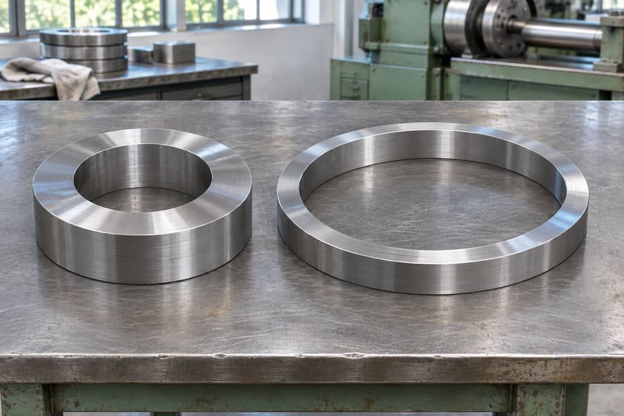
Ring rolling expands the pierced preform while reducing and shaping its cross-section. The workpiece rotates between driven and supporting tools, allowing successive reductions to act around the circumference.
Radial Rolling
The main roll presses the ring’s outer surface while a mandrel supports its inner surface. Closing the gap reduces wall thickness and increases diameter, converting cross-sectional thickness into circumferential growth.
Operators control feed and reduction so the ring grows steadily. Excessive or poorly coordinated reduction can cause local overworking, irregular growth, or loss of roundness. The mandrel position and contact also affect inner diameter and radial reduction, so operators monitor actual ring growth rather than relying only on commanded tool movement.
Unexpected growth can indicate poor concentricity, temperature variation, tool misalignment, or unstable contact. Correcting the cause helps prevent ovality and uneven wall thickness.
Axial Rolling
Axial rolls act on the upper and lower faces to control ring height and help form the cross-section. Radial rolling primarily reduces wall thickness and expands diameter; axial rolling manages height and supports the intended section geometry.
The actions interact. Reducing height changes cross-sectional area and can affect radial growth, while wall reduction influences material movement toward the ring faces. Operators coordinate radial and axial reductions rather than treating them as separate operations.
For stepped or profiled rings, tooling and preform design must direct material into the required contour. Poor material distribution can leave one region overfilled while another remains undersized, causing excess machining or rejection.
Coordinating Rolling and Section Formation
Operators monitor ring rotation, radial feed, axial reduction, and temperature as the ring grows. Outside diameter, inside diameter, wall thickness, height, and section shape indicate whether deformation is following the planned route.
The ring cools during rolling and handling. As temperature falls, deformation resistance rises; continuing outside the material’s suitable forming range can increase cracking risk or produce uneven forming. Temperature differences around the circumference can also cause inconsistent growth, so the sequence must be completed within grade-specific process requirements.
Ovality, wobble, surface damage, or unexpected dimensional growth may signal misalignment, uneven preform geometry, unstable tool contact, or local cooling. Correcting the cause during forming is more effective than relying on machining to compensate for a distorted section.
Plain rings require stable diameter growth and a uniform section; profiled rings also need controlled material flow into the contour and sufficient machining stock.
Cooling and Grade-Specific Heat Treatment
After rolling, the ring requires a cooling route suited to its material grade, cross-sectional dimensions, and subsequent heat-treatment requirements. Cooling affects residual stress, dimensional stability, and the condition of the material entering later operations.
Controlled Cooling
Cooling should be managed according to the material specification rather than applying one procedure to every ring. Differences in wall thickness and section geometry can cause uneven heat loss between the inner, outer, and end surfaces.
Uneven cooling may produce residual stresses or dimensional distortion. Operators therefore control the cooling method and handling sequence to reduce temperature differences and avoid unnecessary mechanical restraint.
Important production considerations include:
- Section thickness: Thicker regions retain heat longer than thinner sections, potentially creating uneven cooling conditions.
- Ring geometry: Changes in cross-section influence heat distribution and the likelihood of distortion.
- Material response: Different steel and aluminum grades respond differently to cooling rates and temperature changes.
- Subsequent processing: The cooling route must remain compatible with the planned heat-treatment and machining sequence.
Heat Treatment for Steel Rings
Steel heat treatment depends on chemical composition, hardenability, section size, and specified mechanical properties. The selected treatment must address the actual grade and ring geometry.
Common processes include:
- Normalizing: Refines the microstructure and establishes a more consistent material condition where appropriate.
- Annealing: Reduces hardness or improves machinability, depending on the selected grade and treatment.
- Quenching and tempering: Develops the required strength and toughness through controlled heating, quenching, and subsequent tempering.
- Stress relieving: Reduces residual stresses when required by the manufacturing route or component specification.
The same treatment cannot automatically be transferred between different steel grades. Hardenability and section thickness influence how the ring responds, particularly when the cross-section is substantial.
Heat Treatment for Aluminum Rings
Aluminum heat treatment follows alloy-specific requirements. Heat-treatable alloys may undergo solution heat treatment, quenching, and artificial or natural aging to develop their specified mechanical properties.
Non-heat-treatable aluminum alloys do not respond to precipitation-hardening treatments in the same way. Their final properties depend more heavily on alloy composition and processing condition.
Quenching also requires attention because uneven cooling can distort large ring sections. The treatment plan should consider dimensional stability alongside the required mechanical properties.
Following heat treatment, inspection verifies whether the material condition satisfies the agreed specification. Hardness and mechanical testing should be selected according to the required acceptance criteria rather than treated as interchangeable measurements.
Machining Allowance and Finishing Operations
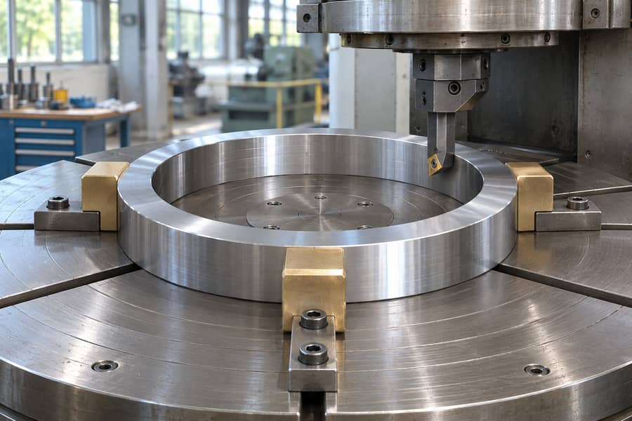
Rolled rings frequently require machining to achieve their specified final dimensions, surface condition, and geometric accuracy. The machining plan must account for the material remaining after forging and any dimensional changes introduced during heat treatment.
Machining Allowance Planning
Machining allowance is the additional material retained beyond the finished drawing dimensions for removal during subsequent operations. It provides stock for correcting surface irregularities and establishing the required geometry.
Allowance planning begins before billet preparation because insufficient stock cannot always be corrected after rolling. Excessive stock, however, increases machining time, material removal, and production cost.
Engineers should consider:
- Outside diameter: Reserve sufficient material for turning the external surface to its specified dimension.
- Inside diameter: Provide adequate stock for boring or internal turning, particularly when the pierced opening is not perfectly uniform.
- Ring height: Allow material removal from both faces where parallelism and final height require machining.
- Profile geometry: Consider additional stock around shoulders, steps, grooves, and other shaped features.
- Heat-treatment changes: Account for possible distortion or dimensional movement before establishing final machining requirements.
Machining allowances should be based on the actual manufacturing route and drawing requirements. A single allowance assumption is unsuitable for rings with substantially different section geometries.
Machining and Delivery Conditions
The required finishing scope determines whether a ring is supplied in its forged, rolled, or machined condition.
| Delivery condition | Typical processing scope | Buyer considerations |
| As-forged | Supplied after forging and specified processing | Suitable when further machining is planned by the buyer |
| As-rolled | Supplied following ring rolling and required subsequent processing | Confirm dimensional condition and remaining machining stock |
| Rough-machined | Major surfaces and dimensions receive preliminary machining | Check remaining stock for final machining |
| Precision-machined | Machined to agreed drawing requirements | Confirm final dimensions, surface finish, and inspection scope |
Common machining operations:
- Turning: Produces the required outside and inside cylindrical surfaces.
- Boring: Enlarges or corrects the central opening.
- Facing: Establishes the required end-face geometry and ring height.
- Milling: Produces specified features that cannot be completed through turning alone.
- Grinding: Provides additional surface finishing where the drawing requires it.
The machining sequence should establish suitable reference surfaces before controlling related dimensions. Poor datum selection can produce alignment errors even when individual machined surfaces appear dimensionally acceptable.
For precision-machined rings, inspection should take place after the relevant finishing operations. Measuring only the rough-machined condition cannot establish whether the final drawing requirements have been achieved.
Defect Prevention, Inspection and Quality Acceptance
Ring quality depends on controlling material condition throughout production and verifying the finished component against agreed requirements. Inspection should identify defects that could affect structural integrity, dimensions, or subsequent service.
Common Manufacturing Defects and Their Causes
Defects can originate during billet preparation, heating, piercing, rolling, cooling, or machining. Identifying their possible process origins helps determine where preventive controls and inspection checkpoints are most useful.
| Defect | Possible manufacturing cause | Inspection method and limitations |
| Laps and folds | Improper material flow, unsuitable preform geometry, or excessive local deformation | Visual, magnetic particle, or penetrant testing where applicable; subsurface extent may require further evaluation |
| Surface cracks | Unsuitable forming conditions, material defects, or thermal stresses | Visual, magnetic particle, or penetrant testing; surface methods cannot establish internal crack depth |
| Internal discontinuities | Material imperfections or incomplete consolidation during processing | Ultrasonic testing; detection depends on discontinuity orientation, size, geometry, and calibration |
| Ovality | Uneven rolling, asymmetric preform, or inconsistent tool contact | Dimensional measurement at multiple circumferential positions |
| Eccentric bore | Misaligned piercing or uneven radial deformation | Bore measurement and concentricity checks against agreed datums |
| Uneven wall thickness | Irregular material distribution or inconsistent radial reduction | Wall-thickness measurements at specified locations |
| Surface scale or damage | Heating conditions, oxidation, handling, or tool contact | Visual examination and dimensional checks; visual inspection cannot verify internal material integrity |
These inspection methods have different detection capabilities. Selecting a test requires consideration of material properties, defect location, component geometry, and the applicable inspection specification.
Non-Destructive Testing
Non-destructive testing provides additional information about surface and internal material conditions without destroying the finished component.
- Visual inspection: Identifies visible cracks, folds, scale, handling damage, and obvious surface irregularities.
- Ultrasonic testing: Evaluates internal discontinuities, with sensitivity influenced by ring geometry, material structure, probe arrangement, and calibration.
- Magnetic particle examination: Where the alloy can be magnetized, a particle indication may reveal a discontinuity at the surface or slightly beneath it.
- Penetrant examination: A liquid enters openings exposed at a clean, nonporous surface; the developed indication helps the inspector locate them.
The test plan may need complementary techniques because each responds to different kinds and locations of discontinuity. For example, penetrant testing cannot reveal internal discontinuities, while ultrasonic testing may have limitations around complex profiles or unfavorable defect orientations.
Inspection procedures should therefore specify test coverage, surface preparation, equipment calibration, reference standards, and acceptance criteria.
Mechanical and Dimensional Verification
Mechanical testing confirms whether the processed material meets its specified properties. Chemical composition, tensile strength, elongation, impact performance, and hardness may be required individually or in combination.
Test specimen location and orientation matter because a ring’s properties can vary with section thickness, deformation history, and heat-treatment conditions. The agreed sampling plan should represent the relevant product condition.
Dimensional inspection should compare the component with the drawing using clearly established reference points.
Typical measurements include:
- Outside and inside diameters.
- Overall height and face geometry.
- Wall thickness at designated positions.
- Roundness, concentricity, and parallelism where specified.
- Machined surface dimensions and finish requirements.
Hardness measurements alone do not establish complete mechanical performance. Likewise, acceptable external dimensions do not demonstrate the absence of internal discontinuities.
Quality Acceptance Requirements
Acceptance criteria should be agreed before production begins. They define which dimensions, material properties, testing methods, and defect classifications determine whether the ring is acceptable.
The inspection plan should identify applicable material standards, testing procedures, sampling locations, and reporting requirements. Where a customer drawing specifies additional requirements, those should be incorporated into the production and inspection documentation.
Drawing Review and Final Delivery at Boberry
The final stage connects manufacturing results with the customer’s technical and purchasing requirements. Boberry reviews the drawing, material specification, finishing scope, and inspection requirements to establish an appropriate production and delivery route.
Reviewing Drawings and Manufacturing Requirements
Before production, the drawing review should resolve requirements that could affect billet planning, rolling, heat treatment, or machining.
Important details include:
- Material specification: Confirm the required grade, applicable standard, and material condition.
- Ring geometry: Identify outside diameter, inside diameter, height, wall thickness, and profile details.
- Machining requirements: Establish which surfaces require finishing and the necessary machining allowances.
- Heat treatment: Specify the required treatment and mechanical properties.
- Inspection requirements: Define dimensional checks, mechanical tests, and applicable nondestructive testing.
- Documentation: Confirm material traceability, inspection records, and required production documents.
Ambiguous dimensions or missing acceptance requirements should be clarified before manufacturing. Otherwise, the supplier and buyer may interpret the same drawing differently, creating avoidable inspection disputes.
Confirming the Delivery Condition
The agreed delivery condition determines how much processing must be completed before shipment.
An as-forged or as-rolled ring may suit a buyer with its own machining arrangements. Rough-machined rings provide partially finished surfaces, while precision-machined components require closer coordination of datums and final inspection requirements.
The final agreement should identify which dimensions are controlled at delivery and which operations remain the buyer’s responsibility.
Final Inspection and Documentation
Before delivery, the inspection results should be checked against the approved drawing and purchase requirements. Any specified deviations must be reviewed and accepted through the agreed approval process rather than assumed acceptable.
Agree which records must travel with the shipment: evidence of material identity, the thermal-processing history, measured dimensions and any ordered property or nondestructive examinations.
This final review connects the manufacturing route with the actual acceptance requirements, ensuring that the supplied ring’s material condition, dimensions, finishing scope, and inspection records correspond to the agreed order.