

Roll forging and closed die forging both shape heated metal, but they use different tooling and deformation sequences to produce components with distinct geometric requirements.
Neither process is universally better; the right choice depends on geometry, material distribution, production needs, finishing operations, and whether a combined preform-to-finish route is practical.
Understanding Roll Forging and Closed Die Forging
Roll forging uses profiled rotating rolls to deform heated bar or billet stock progressively. In longitudinal roll forging, the workpiece advances through shaped grooves that change selected cross-sections along its length.
Successive grooves progressively change the cross-section, redistributing material from thicker regions into narrower or elongated sections. Unlike flat rolling, the roll surfaces carry profiles designed for the required longitudinal shape.
Closed die forging forms the blank within paired impressions; this is why the conventional process is also called impression-die forging. Heated stock is compressed between the dies, forcing material toward the cavity geometry.
The operation may include bending, edging, fullering, blocking, and finishing. Earlier stages redistribute stock; the finishing impression establishes the principal forged shape.
The term “closed die” does not mean that excess metal cannot escape. Conventional impression-die forging commonly allows material to flow between the die faces as flash, which is removed during a separate trimming operation.
Flashless forging is a distinct, deliberately designed approach. It requires suitable geometry, accurate stock-volume control, and specific tooling conditions; it should not be assumed for every closed-die process.
The practical distinction is that roll forging progressively shapes a longitudinal profile, while closed die forging forms material within shaped impressions. They can be alternatives or complementary stages.
Combining Roll Forging with Closed Die Forging
A combined route uses roll forging to prepare stock before impression-die finishing. It is especially relevant when an elongated component has sections requiring substantially different amounts of material.
The roll-forged preform is not necessarily close to the final component. Its purpose is to position material where the finishing dies need it, reducing abrupt movement during later forming.
A typical sequence may include:
- Stock preparation: Cut billet or bar stock to a suitable starting length and establish its required material condition.
- Roll preforming: Pass heated stock through profiled grooves to distribute material along the longitudinal axis.
- Transfer and temperature control: Manage handling time and temperature before subsequent forming, with reheating if the process requires it.
- Impression-die forming: Use blocker and finishing impressions, where needed, to develop the required three-dimensional shape.
- Trimming and downstream work: Remove flash where formed, then complete specified heat treatment, machining, and inspection.
Each process performs a different task. Roll forging handles longitudinal redistribution, while impression dies form details and features that cannot be produced efficiently by the roll profile alone.
For example, a long component may need a narrow central section and heavier ends. Roll forging can distribute stock along its length before die impressions form the end features and refine the overall shape.
A well-designed preform can help limit excessive local flow or incomplete cavity filling, but only when volume distribution and sequence are properly planned.
The combined route adds handling, tooling, heating coordination, and process-control requirements. It is worthwhile only when forming or material-use benefits justify those steps.
A simple longitudinal profile may need roll forging alone, while a compact component with complex three-dimensional features may proceed directly through a suitable die-forging sequence. Selection should follow the part geometry and volume distribution.
Geometry and Component Applications
Geometry is often the first screening factor because the processes suit different patterns of cross-sectional change.
Components Suited to Roll Forging
Roll forging is useful for elongated components whose cross-section changes along the longitudinal axis. Examples include stepped shafts, tapered sections, levers, and preforms for more complex elongated forgings.
The rolls can shape selected regions while adjacent sections retain different dimensions. This is useful when material must be shifted along a bar without forming every surface into a complex cavity.
The process is less suited to lateral branches, enclosed recesses, or intricate features distributed around several sides. Such details may require later die forging or machining.
Important design considerations include:
- Length and section: The part needs sufficient working length for the planned roll sequence.
- Profile transitions: Abrupt changes may complicate material movement and require revised radii or additional passes.
- Cross-section: Suitable round, oval, rectangular, or other sections depend on the roll-groove design.
- Feature orientation: Features extending around multiple faces may exceed the practical scope of longitudinal roll profiles.
Components Suited to Closed Die Forging
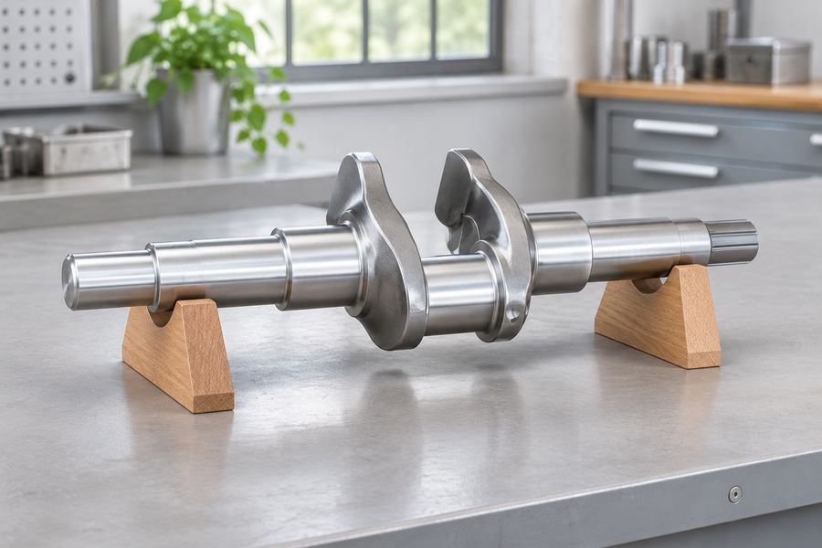
Closed die forging is generally better suited to defined three-dimensional shapes, including connecting rods, flanges, gear blanks, and components with bosses, ribs, or connected sections.
Die impressions can control external form across multiple planes. The design still needs suitable draft, corner radii, parting-line placement, and a practical method of removing the forging.
Deep recesses, thin projections, narrow webs, and sharp transitions can complicate die filling. These features require assessment against material flow, die access, and the intended machining condition.
Closed die forging does not eliminate machining. Holes, bearing seats, threads, sealing faces, and close-tolerance interfaces commonly require subsequent machining when specified by the drawing.
When Geometry Favors a Combined Route
Some components combine a long body with substantial section changes and complex end features. Roll forging may establish longitudinal mass distribution before closed die impressions form those details.
Mark the drawing to separate geometry needed in the forging from details that finishing tools can produce. Drawings should identify functional surfaces, noncritical contours, and required machining stock.
Material Distribution, Metal Flow, and Forging Quality
Material distribution describes where billet volume is positioned before and during deformation. Process planning must match the starting stock and preform to the material required at each section of the finished forging.
In roll forging, profiled grooves progressively reduce selected cross-sections and redistribute material along the workpiece. The pass sequence must avoid forcing excessive material through a transition in one operation.
The preform should be assessed section by section, not only by its overall outline. Too little stock can restrict later die filling; excess material can increase flash, trimming, or local deformation demands.
In closed die forging, material must flow into the impression without folding over itself or leaving unfilled regions. Fullering, edging, bending, and blocking can position stock before the finishing impression.
Flash in conventional impression-die forging has a functional role as well as a removal cost. Resistance at the flash land can help promote cavity filling, but flash location and dimensions require control through die design.
Neither process automatically produces superior grain flow or mechanical properties. Deformation direction, local strain, temperature history, material grade, and subsequent heat treatment all influence the finished condition.
Potential problems include:
- Laps and folds: Poorly matched preform geometry or metal movement can cause material to fold over itself.
- Underfilling: Insufficient stock, unsuitable temperature, or restricted flow can leave parts of an impression incomplete.
- Excessive flash: Poor volume distribution or die design can increase material loss and trimming work.
- Surface defects: Scale, handling damage, or forming conditions can affect the surface and require evaluation before machining.
- Dimensional variation: Changes in stock, temperature, transfer timing, or tooling condition can alter the formed profile.
A sound comparison asks whether the sequence places sufficient material in each region, supports controlled deformation, and leaves stock for finishing.
Buyers should identify critical sections, material condition, inspection locations, and machined surfaces in the drawing and acceptance specification.
Tooling Requirements and Production Setup
Tooling differs because each process creates deformation through a different contact arrangement. Roll forging uses profiled grooves for successive reductions, while closed die forging relies on matched impressions.
For roll forging, design must account for starting stock, final longitudinal profile, pass sequence, material movement, and workpiece handling. Groove transitions should distribute deformation progressively rather than demand excessive change at one location.
Closed die tooling is designed around the component’s three-dimensional geometry. The die set may include blocker and finisher impressions, plus trimming tooling when conventional flash forms.
Important design decisions include:
- Parting line: Its position affects die layout, material flow, flash location, and potential mismatch.
- Draft and radii: Suitable release angles and transitions help hot material fill the impression and allow part removal.
- Preform design: A blocker or roll-forged preform must place material near heavy sections without creating unnecessary excess.
- Trim arrangement: Flash removal belongs in the production plan, not as an afterthought.
Setup also involves stock preparation, heating, transfer, lubrication where applicable, and coordination between forming stages. Controls depend on alloy, section size, equipment, and the approved process plan.
When roll forging precedes closed die finishing, the handoff is especially important. The preform must reach the next operation with suitable dimensions, orientation, and temperature. Transfer delays or inconsistent placement can affect cavity filling.
Tooling should be evaluated across the complete sequence. A roll-only route, impression-die route, and combined route may require different equipment, handling steps, and supporting tools.
Production Economics, Machining, and Finishing Requirements
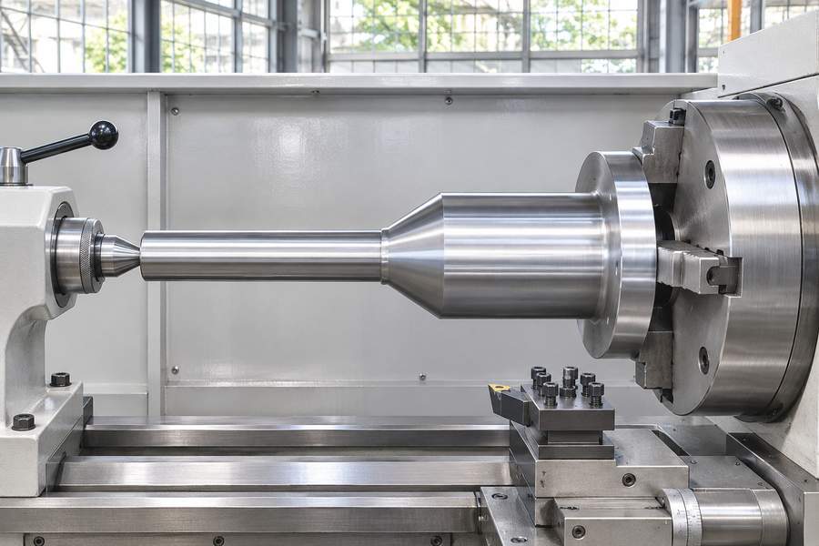
A fair cost comparison includes dedicated tooling, setup, material input, scrap and flash, production rate, secondary operations, inspection, and design stability.
Roll forging may be attractive when repeated longitudinal profiles can be produced through a direct sequence. Its economics depend on groove complexity, pass count, stock preparation, and whether the profile reduces later forming or machining.
Closed die forging may require greater investment in matched impressions and related tooling. This can be justified when geometry and repeat demand support dedicated dies, but uncertain volumes make tooling amortization harder.
A combined route adds an operation and handling. It makes sense when the roll-forged preform improves material placement or simplifies final impression forming, not merely because both processes are available.
Material utilization needs careful interpretation. Roll forging redistributes stock along the workpiece, while conventional closed die forging commonly generates flash for trimming. Actual use depends on billet size, preform design, cavity volume, trimming, and rejected parts.
| Evaluation factor | Roll forging | Closed die forging |
| Main tooling | Profiled rolls and grooves | Matched impression dies |
| Deformation | Progressive, longitudinal | Cavity-directed, three-dimensional |
| Typical geometry | Elongated profiles and section changes | More complex external forms |
| Material distribution | Along workpiece length | Into die impressions |
| Flash | Process- and design-dependent | Common in conventional impression-die forging |
| Tooling economics | Roll profile and pass requirements | Die complexity and production quantity |
| Secondary work | Further forming or machining may be needed | Trimming, heat treatment, and machining may be needed |
Machining remains important for both routes. Forged surfaces may retain scale, draft, parting features, or dimensional variation that does not meet the finished drawing.
Allowance should be assigned to surfaces requiring cleanup. Functional diameters, bearing seats, bores, threads, sealing faces, and datum surfaces often need machining to achieve specified dimensions and relationships.
Unneeded stock ties up the machine for extra cuts and turns more purchased metal into chips. Insufficient stock can leave surfaces that cannot be cleaned up or prevent critical features from reaching their required positions.
The forging drawing should distinguish the forged envelope from final machined geometry and identify surfaces that may remain as-forged. Downstream work may include trimming, descaling, heat treatment, straightening where specified, machining, and inspection.
Heat treatment can affect dimensions through distortion or stress redistribution. Critical datums and inspection stages should therefore be planned around the agreed thermal sequence.
Defect Prevention, Inspection, and Quality Acceptance
Quality planning should connect potential defects to the operation where they may arise and the method used to prevent or detect them. A final dimensional check cannot establish every aspect of forging integrity.
In roll forging, monitor groove alignment, pass progression, stock condition, temperature, and material movement. Poor transitions or stock distribution may contribute to laps, surface damage, or an inconsistent longitudinal profile.
In closed die forging, preform volume, cavity filling, die condition, parting-line alignment, and temperature influence the result. Potential issues include underfilling, folds, mismatch, excessive flash, and surface discontinuities.
A combined route needs checks between operations. The roll-forged preform should be assessed against the dimensions and material distribution required by the finishing dies, not merely accepted because it resembles the final outline.
Inspection should reflect the component’s service and drawing requirements. Typical elements include:
- Visual examination: Identify visible laps, cracks, scale-related damage, and other discontinuities.
- Dimensional inspection: Check critical lengths, diameters, section transitions, alignment, and datums.
- Material verification: Confirm grade and traceability through agreed documentation.
- Mechanical testing: Specify properties, sampling locations, specimen orientation, and acceptance criteria.
- Nondestructive examination: Define method, coverage, timing, and acceptance level when required.
Testing should be specified, not assumed. Methods must suit the material, geometry, defect concern, and inspection stage. If machining is needed to expose a surface, include that step in the route.
Acceptance should distinguish the forged condition from the finished condition. A forging may meet its intermediate drawing while still requiring machining and final verification before satisfying the component specification.
Process Selection and Drawing Review for Engineering Buyers
The process decision should begin with the finished component, then work backward to the forging envelope and production sequence. Avoid choosing solely by process name or broad claims about strength, accuracy, or material savings.
Roll forging suits elongated components requiring material redistribution between sections. Closed die forging is relevant when shaped features extend across several directions. A combined route may suit parts needing both longitudinal preforming and complex impression-die finishing.
Projects involving forged shafts may require review of stepped sections, end features, machining stock, and final datums. The drawing, not the product category alone, determines the appropriate route.
Before requesting a quotation, buyers should provide information needed to assess the part and its manufacturing condition:
| Buyer checkpoint | Information to provide or confirm |
| Geometry | Controlled 2D drawing, 3D model, critical sections, orientation |
| Material | Grade, applicable specification, supply condition |
| Production demand | Initial and annual quantity, design stability |
| Forging route | Roll-only, closed-die, or preform-plus-finish sequence |
| Machining | Finished dimensions, datums, machined surfaces, allowances |
| Quality | Properties, inspection methods, sampling, acceptance criteria |
| Delivery condition | Heat treatment, surface condition, trimming, machining, documents |
The drawing review should identify function-critical dimensions and features that can tolerate forging variation. It should show where machining stock is needed and how final datums will be established.
Material specifications should state the grade and condition clearly. Required properties or nondestructive testing should include applicable methods, locations, and acceptance criteria.
The supplied condition must also be agreed. An as-forged blank is not equivalent to a trimmed, heat-treated, rough-machined, or fully machined component.
For Boberry Machining, process discussions can begin with the controlled drawing, material requirements, quantity forecast, critical dimensions, and inspection expectations. These details help assess whether roll forging, closed die forging, or a combined route is appropriate.
Any proposed change to the forging envelope, parting line, draft, machining allowance, or inspection plan should be reviewed against functional requirements before tooling is finalized.