
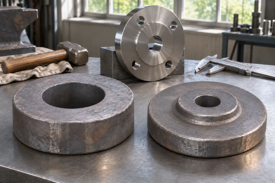
Open-die and closed-die forging shape flange blanks with different tooling, influencing geometry, tooling investment, production flexibility, and material flow. Neither route suits every order; selection depends on design and quantity.
Both methods require machining of bores, bolt holes, and gasket faces. Press or hammer describes force application, not die type, while ring rolling remains a separate forming route.
What Are Open Die Forged Flanges and Closed Die Forged Flanges?
The terms describe how a flange blank is formed, not the finished flange connection or facing. Open-die forging works the stock through successive squeezes or blows using simple tools; an enclosing impression does not prescribe the complete profile.
In closed-die, or impression-die, forging, shaped die surfaces guide the heated metal toward a defined preform. The cavity can establish hubs, transitions, and other contours before machining, although the finished dimensions still depend on later operations.
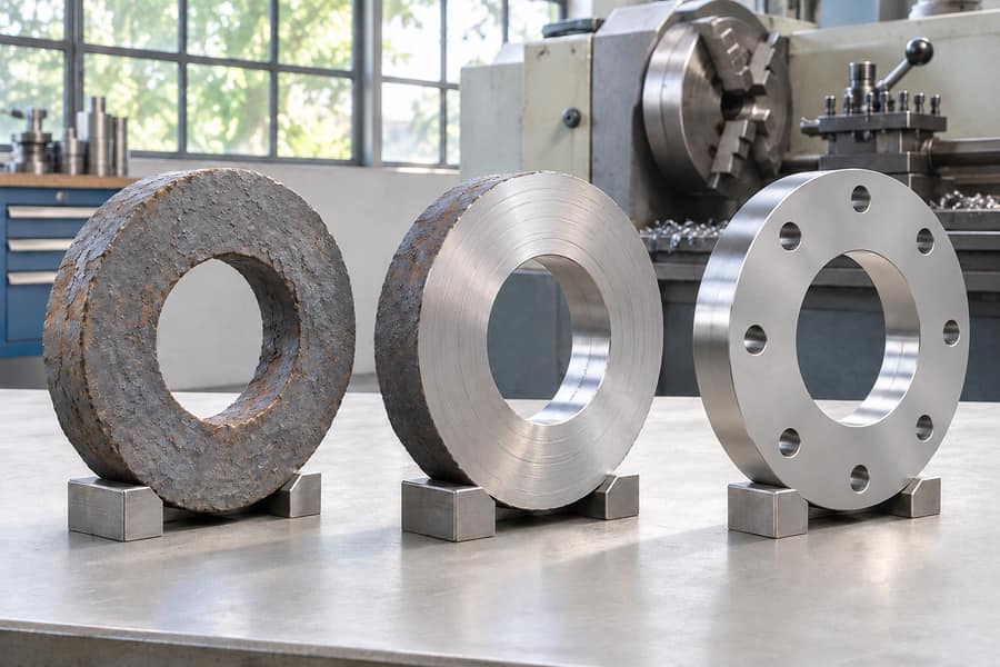
Neither method produces a ready-to-install flange by itself. Forging creates a rough or near-net blank; machining establishes the bore, bolt pattern, thickness, facing, and other drawing-controlled features.
Open Die and Closed Die Tooling
Open-die tooling allows the workpiece to be repositioned and rotated during deformation. This suits varied blank dimensions where a dedicated impression for every design may not be justified.
Closed-die tooling uses matched impressions to constrain metal flow. Die design must account for billet volume, material behavior, draft, parting-line location, and any flash gutter.
Flashless forging is a specific closed-die arrangement, not a synonym for all closed-die forging. It requires close control of billet volume and cavity filling; conventional impression-die operations may intentionally produce flash that is trimmed afterward.
How Are Open Die and Closed Die Forged Flanges Manufactured?
Open Die Forging Process
Production begins with a billet selected for the specified material and blank dimensions, then heated under controlled conditions for deformation.
Upsetting increases a section by compression, while drawing reduces a section and changes its length. The sequence depends on stock, flange profile, and intended material flow.
The workpiece is turned or repositioned to develop a disc, ring-like, or hubbed preform. Since the tools do not define a complete cavity, process control and machining establish dimensional accuracy.
After forging, the blank may receive material-appropriate heat treatment, cleaning, and inspection as required by the specification and manufacturing plan.
Closed Die Forging Process
A prepared, heated billet is placed between aligned impression dies. Forging force drives the metal into the intended portions of the cavity.
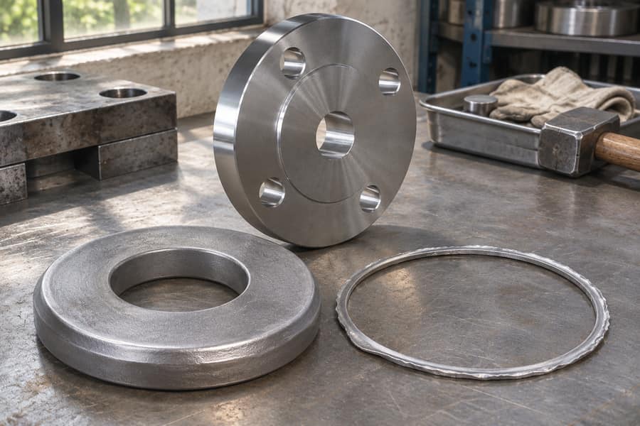
The operation may use several stages. Excess metal can flow into a flash gutter, assisting cavity filling but creating material that must later be trimmed.
The forged piece is removed and flash trimmed where applicable. After trimming, the production plan sets the necessary thermal processing, surface preparation, and checks for that grade and component.
Closed-die forging can create a more defined starting profile than open-die forging, but it does not eliminate machining. The blank still needs allowance for the final bore, bolt holes, gasket face, and specified dimensions.
Common Operations After Forging
Both routes may require scale removal, heat treatment, rough and finish machining, and inspection. The sequence depends on material condition, blank geometry, and acceptance criteria.
Separate the forging scope from finished-flange scope: a forged-blank quotation may exclude drilled holes, finished facings, or final dimensional reports.
How Tooling Changes Flange Blank Production
The difference lies in how much of the blank profile is imposed by the dies. Open-die forging offers more freedom to manipulate the stock, while impression dies provide a defined cavity for producing repeatable preform geometry.
| Comparison factor | Open-die forging | Closed-die forging |
| Tooling | Flat or relatively simple dies | Shaped impression dies |
| Shape flexibility | Adaptable to varied blank geometries | Bound by the designed cavity |
| Dedicated tooling | Usually less extensive for a new shape | Requires an impression designed for the part |
| Production pattern | Useful for varied or customized orders | Often suited to repeated designs |
| Preform repeatability | Depends strongly on operator and process control | Die geometry supports consistent preforms |
| Material use | Depends on stock selection and machining allowance | Depends on cavity design, flash, and trimming |
| Shape detail | Generally suited to simpler preforms | Can form more detailed profiles and transitions |
These are general tendencies, not guarantees. A carefully controlled open-die process can produce suitable blanks, while a poorly designed closed-die operation can create underfill, laps, mismatch, or excessive machining requirements.
Compare the complete route, not forging alone. Tooling, billet size, trimming, heat treatment, machining, inspection, and scrap all affect the cost of an accepted flange.
Which Flange Designs Are Better Suited to Each Forging Method?
When Open Die Forging May Be Appropriate
Open-die forging is often considered for large or relatively simple flange blanks, including disc-shaped and ring-like preforms. It can also suit customized designs when dimensions vary between orders and dedicated tooling would see limited use.
A small batch with a straightforward profile may suit open-die production, subject to equipment, stock availability, dimensions, and machining requirements.
Open-die preforming may also prepare stock for ring rolling; assess the blank by how well it supports that next operation.
When Closed Die Forging May Be Appropriate
Closed-die forging may be attractive when the same flange blank is produced repeatedly and the order can justify dedicated impression tooling. A shaped cavity can form hubs and transitions into the preform before finish machining.
A recurring order with a defined hub profile may benefit from a consistent die-produced blank, but tooling, die life, setup, and expected savings still require review.
Complex cavity geometry does not automatically favor closed-die forging: the billet must fill the cavity, release from the dies, and remain practical to trim and machine.
Design Details That Influence the Choice
Review outside diameter, thickness, hub dimensions, transitions, and mass. These affect billet selection, deformation sequence, die design, handling, and machining stock.
Draft, parting-line location, and cavity access matter for impression dies. Open-die planning instead asks whether repositioning can form the shape consistently.
Separate finished dimensions from blank dimensions on drawings. If the supplier proposes the blank, provide datums, known allowances, and surfaces that must remain available for finishing.
Applying Force with a Press or Hammer
Press and hammer describe how force reaches the workpiece; open-die and closed-die describe the tooling arrangement. These are separate classifications, so neither equipment type belongs exclusively to one die method.
Press Forging
A press applies compressive force through a controlled stroke, maintaining contact as the workpiece deforms. This suits planned deformation through a substantial section.
Presses can operate with open or impression dies when compatible. Selection depends on force, stroke, workpiece dimensions, material response, and production arrangement.
Hammer Forging
A hammer delivers impact energy through successive blows. The workpiece may be repositioned between blows to develop the intended shape.
Hammers can also operate with open or closed dies. Suitability depends on workpiece mass, die design, deformation requirements, and the control needed.
Ask which die arrangement forms the blank and which equipment applies force. “Hammer forged” alone does not identify open or impression dies.
Where Does Ring Rolling Fit into Forged Flange Manufacturing?
Ring rolling is a separate operation that expands a ring-shaped workpiece. Rolls reduce the wall while increasing diameter to develop the required ring geometry.
A route may use open-die upsetting and piercing to prepare a ring preform, followed by rolling to develop its dimensions and cross-section.
This route can suit annular flange blanks, but ring rolling is not another name for open-die forging; the operations use different tooling and deformation functions.
Ring rolling develops ring geometry rather than every flange feature in one impression. The ring still needs machining for its bore, faces, bolt circle, and connection details.
For a ring-rolled blank, state whether preforming, rolling, heat treatment, and machining are included, and define the required dimensions and supply condition.
Material Flow, Mechanical Properties, and Forging Soundness
Material Flow and Grain Direction
Plastic deformation changes billet shape and influences grain flow. In open-die work, upsetting, drawing, and workpiece rotation determine how the material is worked.
In closed-die forging, the cavity guides metal toward hubs and transitions. Local flow depends on billet volume, die geometry, temperature, friction, and deformation sequence.
Neither route creates one universal grain-flow pattern. Assess whether the process produces a suitable material condition in the flange’s load-carrying regions.
What Determines Mechanical Properties?
Mechanical properties depend on alloy, starting condition, forging practice, section size, and heat treatment. Die category alone cannot establish strength, toughness, hardness, or fatigue performance.
For cyclic service, the design and material specification should define required properties; processing and verification must meet them without assuming forging improves every property.
Heat treatment follows the material and required condition. Carbon, stainless, alloy, and duplex grades may need different procedures, so one cycle cannot be assumed for all.
Soundness and Potential Defects
Potential issues include surface cracks, laps, underfill, die mismatch, internal discontinuities, and oxidation. Risk depends on material condition, heating, deformation, tooling, and control.
Open-die forging does not guarantee soundness, and closed-die forging does not eliminate defects. Set inspection according to the component, material, service, and acceptance criteria.
Where internal quality matters, specify required nondestructive examination, coverage, acceptance basis, and reporting. Confirm that the supplier’s scope includes the examination.
Material Selection and Heat Treatment for Forged Flanges
Forged flanges are available in carbon, stainless, alloy, and duplex steel families. Selection begins with the fluid, environment, design conditions, fabrication needs, and material specification.
Consider corrosion resistance, mechanical requirements, weldability, and minimum design temperature. Higher alloy content is not automatically beneficial when service conditions do not require it.
ASTM material or product specifications identify requirements for the material form and grade. Put the complete product-standard reference and alloy designation on the order; a family name leaves too much undefined.
Set the thermal cycle from the requirements for the actual alloy and the condition in which the flange must be supplied. Depending on the grade, the required condition may involve normalizing, quenching and tempering, solution treatment, or another specified procedure.
Ask the supplier to identify the heat-treatment condition and available records. Verify that records correspond to the supplied material and production lot.
Evaluate forging method and material separately. Either die route may suit different material families if it meets geometry and material-condition requirements.
Machining Requirements for Open Die and Closed Die Forged Flanges
Forged blanks require machining to meet the drawing. The amount depends on blank geometry, stock allowance, and finished features.
Bores, Bolt Holes, and Flange Faces
Machine the bore to the specified diameter and geometry. Drawings should define datums and required relationships to the outside diameter and flange face.
Machine bolt holes to the specified number, diameter, and bolt circle. Verify their positions against the drawing to maintain alignment with mating equipment.
Machine the gasket face to the specified facing and surface condition. Raised-face, flat-face, and other arrangements come from the drawing or standard, not the forging method.
Blank stock may differ between routes, but both require controlled machining. Forging establishes the starting form; machining establishes the functional geometry.
Custom Machining and Scope Definition
For a custom flange, define bore, bolt circle, facing, thickness, hub profile, and connection type. Separate finished dimensions from blank dimensions.
Clarify responsibility for rough and finish machining, drilling, facing, and post-machining inspection. A quotation that itemizes the machining stages exposes differences hidden in a single finished-piece price.
Standards, Pressure Classes, and Quality Inspection
Material Specifications and Flange Standards
ASTM specifications address material and product requirements, while applicable ASME flange standards establish dimensional rules and pressure-temperature ratings. List both documents in the order: one governs the material product, the other the standardized flange.
An ASTM grade alone does not define finished dimensions, and an ASME flange standard does not replace the need to specify material grade and product form.
Reading a Flange Class Designation
Do not read the number stamped after Class as a pressure-gauge value. Look up the specified material and design temperature in the rating schedule for the flange standard invoked by the project.
Forging does not raise the rating of a flange made to a specified standard and Class. Confirm the standard, material group, size, facing, and design conditions.
Inspection, Documentation, and Traceability
Tie inspection to the drawing, material specification, flange standard, and purchase order. Checks may include visual and dimensional examination, material identification, and specified NDE.
Traceability links the flange to material and manufacturing records, which may include material test records, heat-treatment details, inspection results, and identification.
Define acceptance criteria before production. For ultrasonic or other examination, specify the method, extent, acceptance basis, and report format.
How to Choose Between Open Die and Closed Die Forged Flanges
Start with the finished drawing and service conditions. Identify connection type, facing, material grade, dimensions, quantity, and inspection or traceability requirements.
Ask the supplier to identify the proposed blank route: open-die or impression-die tooling, any ring-rolling stage, and the included post-forging operations.
Compare tooling investment with order quantity and repeat-order potential. Dedicated impression tooling may be hard to justify for a one-off design but worth evaluating for recurring production.
Compare quotations by scope, not unit price alone. Billet preparation, forging, trimming, heat treatment, machining, inspection, documentation, and material use may differ.
| RFQ item | Information to provide |
| Drawing | Current controlled revision and finished-part dimensions |
| Material | ASTM specification, grade, and product form |
| Flange standard | Applicable ASME standard, Class, size, and facing |
| Quantity | Initial order and expected repeat demand |
| Forging route | Proposed open-die or impression-die process and any ring-rolling stage |
| Machining | Bore, bolt circle, bolt holes, gasket face, and finished dimensions |
| Quality | Heat treatment, NDE, inspection, acceptance criteria, and traceability |
Boberry Machining’s forged-flange range includes carbon steel, stainless steel, alloy steel, and duplex stainless steel families, along with weld-neck, slip-on, blind, and other connection types.
Its stated customization scope includes different facings and machining of bores, bolt circles, and flange faces.
If blank dimensions are open, request a proposed blank drawing for approval. Agree on allowances, datums, inspection stages, and finished-part acceptance criteria before production.