
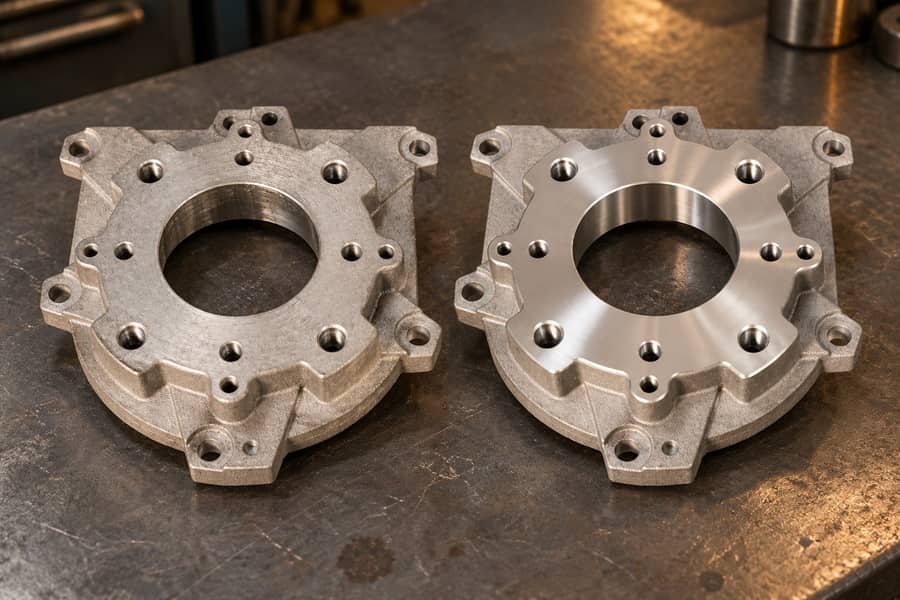
Near net shape casting produces a rough component close to its finished geometry, reducing material that must be cut away. It is a manufacturing objective, not a separate casting process.
Critical surfaces still need machining. Whether the approach lowers overall cost depends on foundry yield, tooling, inspection, scrap recovery, production volume, and the number of acceptable finished parts.
What Is Near Net Shape Casting?
Near net shape casting aims to produce components with geometry and dimensions approaching their final design requirements. The objective is to minimize unnecessary material removal without compromising casting quality or component functionality.
Unlike a dedicated manufacturing process, near net shape production is a design strategy that can be applied to several casting methods. Its effectiveness depends on material properties, geometric complexity, tooling, and achievable dimensional control.
A component does not need to emerge from its mold completely finished to qualify as near net shape. The essential consideration is how closely its cast geometry matches the required finished form.
Near Net Shape vs. Net Shape Manufacturing
Net shape manufacturing produces features that satisfy their final requirements without additional material removal. Near net shape manufacturing allows selected areas to retain material for subsequent finishing.
When reviewing a casting drawing, engineers should identify which surfaces can be used directly after casting and which must be machined to meet functional requirements.
An external housing profile might remain as-cast, while its bearing seats require precise machining.
Near net shape designs therefore combine cast geometry with strategically selected finishing operations. The casting process forms most of the component, while machining establishes features requiring greater accuracy.
Why Near Net Shape Castings Still Require Machining
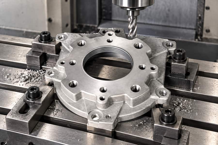
Casting processes involve dimensional variations associated with solidification, shrinkage, tooling, and material behavior. These variations may exceed the permissible tolerances of critical mechanical interfaces.
Several features commonly require secondary machining:
- Bearing seats: Require controlled dimensions, roundness, and alignment for proper bearing installation.
- Sealing faces: Need suitable flatness and surface finish to achieve reliable sealing.
- Precision bores: May require boring, reaming, or finishing to meet dimensional and positional requirements.
- Threaded interfaces: Often require drilling, tapping, or thread machining when direct casting cannot meet specifications.
- Mounting surfaces: May need machining to establish reliable alignment with adjoining components.
The goal is not to eliminate machining indiscriminately. It is to retain necessary finishing operations while avoiding excessive stock removal from surfaces that can meet requirements as-cast.
Design Considerations for Reducing Machining Stock
The potential benefits of near net shape casting begin during component design. Machining allowances, datum selection, internal cavities, and tooling constraints influence how much material can safely be eliminated.
Machining Allowances and Dimensional Accuracy
Machining allowance refers to material intentionally left on a rough casting for subsequent removal. It provides sufficient stock to establish accurate finished dimensions and surfaces.
Excessive allowances increase cutting time and machining chips. Insufficient allowances can prevent complete surface cleanup, particularly when casting variation or distortion shifts material away from the intended machining envelope.
Allowance selection should consider several interacting factors:
- Casting process: Different molding and solidification methods produce different dimensional variation and surface characteristics.
- Material behavior: Alloy shrinkage, distortion, and heat-treatment response influence the final rough casting geometry.
- Feature location: Critical surfaces and widely separated features may require different stock allowances.
- Machining requirements: Tolerances, surface finish, and tool access affect the amount of material needed for reliable finishing.
A uniform allowance across every surface is not always appropriate. Localized allowances can preserve sufficient material around critical features while reducing unnecessary stock elsewhere.
Before reducing allowances, manufacturers should evaluate representative casting measurements. Actual variation provides a stronger basis for design decisions than nominal geometry alone.
Datums, Fixturing, and Machining Access
Near net shape casting reduces machining requirements only when the resulting component can be located, clamped, and finished consistently.
Casting datums establish initial workpiece positioning, while finished machining datums control critical relationships between component features. These references may differ because rough casting surfaces contain dimensional variation.
For example, an equipment housing may use external cast features for initial location before machining a primary mounting face. Subsequent operations can reference that finished surface.
Fixture design must accommodate casting variation without introducing excessive clamping forces or distortion. Locating surfaces also need sufficient accessibility and stability during cutting.
Machining access deserves equal attention. A reduced-stock pocket provides little benefit if its geometry requires unusual tools, additional setups, or difficult tool movements.
Cores, Internal Cavities, and Wall Thickness
Casting cores can produce internal passages, cavities, and recesses that would otherwise require substantial material removal.
For valve bodies and pump housings, properly designed internal geometry may eliminate extensive drilling or boring through solid material. However, core accuracy becomes part of the dimensional-control problem.
Core positioning variation can affect wall thickness and alignment between internal passages and external features. Complex core arrangements also introduce additional tooling and handling requirements.
Wall thickness should support reliable metal flow, feeding, and solidification. Removing material from the design without evaluating these requirements may increase defect risks.
Balancing Casting Complexity and Machining Requirements
Reducing machining stock should not create a casting that is unnecessarily difficult to manufacture.
Parting lines, draft requirements, feeding systems, and mold accessibility can constrain the geometry achievable directly through casting. These limitations vary with the selected process.
An intricate recess might reduce cutting but complicate tooling or solidification. Keeping the cast geometry straightforward and machining only the critical areas can avoid complicated tooling while maintaining the required dimensions.
The preferred design balances casting reliability, machining requirements, dimensional consistency, and tooling complexity rather than minimizing rough casting weight alone.
Which Casting Methods Are Suitable for Near Net Shape Production?
Investment casting, gravity casting, and die casting can support near net shape objectives, although their capabilities differ.
Process selection should follow component requirements rather than assumptions that one method consistently produces less machining or higher material utilization.
Investment Casting
Investment casting uses expendable patterns and ceramic molds to reproduce detailed component geometry. It can be suitable for intricate profiles and selected internal features.
Complex external shapes may be formed close to their finished dimensions, reducing machining across surfaces that do not require exceptionally tight tolerances.
However, pattern production, shell processing, core arrangements, and dimensional variation still influence achievable geometry. Critical surfaces may require machining after casting.
Investment casting can be attractive when reduced cutting offsets its processing and tooling requirements. That balance depends on component design and production quantity.
Gravity Casting
Gravity casting fills molds using gravity rather than high-pressure injection. Suitable permanent-mold configurations can reproduce defined component profiles with reusable tooling.
Mold design and core arrangements influence the complexity of external features and internal cavities. Feeding and solidification requirements can also limit achievable geometry.
Machining may remain necessary around mating faces, bores, and dimensional interfaces. Engineers should establish machining stock using measured casting variation, the component’s geometry, and the dimensional requirements of its finished surfaces.
Gravity casting should therefore be evaluated alongside expected production quantities, alloy compatibility, and the cost of subsequent machining operations.
Die Casting
Die casting uses metal dies to form components, with filling conditions depending on the specific process. Pressure-assisted methods can reproduce detailed geometries under suitable manufacturing conditions.
High-pressure die casting can be appropriate for certain complex, relatively thin-walled components. However, tooling design, metal flow, and internal-quality requirements constrain its application.
Conventional high-pressure die casting can produce gas porosity that affects subsequent heat treatment or welding. Specialized process controls may change suitability, but qualification remains necessary.
Precision bores, sealing interfaces, and threaded features may still require machining. Detailed as-cast geometry does not guarantee that every functional surface meets finished specifications.
Casting Method Comparison
| Comparison Factor | Investment Casting | Gravity Casting | Die Casting |
| Geometry suitability | Intricate profiles and selected internal features | Shapes compatible with gravity filling and feeding | Detailed features compatible with die design |
| Machining implications | Selected precision surfaces still require finishing | Allowances depend on geometry and process capability | Critical interfaces may require finishing |
| Tooling requirements | Pattern, shell, and possible core tooling | Mold and possible core tooling | Reusable die and associated tooling |
| Main limitations | Processing complexity and dimensional variation | Feeding and solidification requirements | Tooling complexity and process-dependent internal quality |
| Selection considerations | Complex geometry and finishing requirements | Alloy, part geometry, and production quantity | Production volume, geometry, and quality requirements |
No method guarantees superior near net shape performance across every application. A meaningful comparison requires evaluating the same finished component requirements under realistic manufacturing conditions.
How Near Net Shape Casting Affects Material Waste and Foundry Yield
Less machining stock generally means fewer chips generated during finishing. It does not automatically mean that the foundry consumes proportionally less metal.
Casting material utilization must account for metal poured into the mold, metal retained in the usable casting, and material separated during processing.
Machining Stock Reduction vs. Foundry Metal Yield
Machining stock reduction measures the decrease in material removed from a usable rough casting to produce the required finished component.
Foundry metal yield measures usable rough casting mass relative to the total metal poured, using a consistent process boundary.
The relationship can be expressed as:
Foundry metal yield (%) = (Usable rough casting mass / Total metal poured) × 100
Gates, runners, and risers are commonly removed before machining. Although they support filling or feeding, their metal does not become part of the usable casting.
A redesigned casting may need less machining stock but a different feeding system. Consequently, foundry metal yield can decrease even while machining chips decrease.
These measurements describe different manufacturing stages and should not be combined into a single material-savings estimate.
Hypothetical Material and Machining Time Comparison
Consider two hypothetical casting designs producing the same finished component. The following assumptions are declared solely to illustrate material accounting and machining-time differences.
Both designs use the same alloy and produce a finished component weighing 0.80 kg. Functional requirements, finished geometry, and acceptance criteria remain identical.
The comparison assumes one successful casting per attempt, with no casting rejection, machining rejection, furnace loss, or additional finishing-related mass removal outside the stated figures.
Poured mass includes the usable casting and attached gates, runners, and risers. Machining time is independently assumed rather than calculated directly from removed material.
| Parameter | Conventional Casting | Near Net Shape Casting |
| Total metal poured | 2.00 kg | 1.90 kg |
| Removed gates, runners, and risers | 0.80 kg | 0.85 kg |
| Usable rough casting mass | 1.20 kg | 1.05 kg |
| Finished component mass | 0.80 kg | 0.80 kg |
| Machining chips generated | 0.40 kg | 0.25 kg |
| Assumed machining time | 18 minutes | 13 minutes |
| Foundry metal yield | 60.0% | 55.3% |
All figures are hypothetical assumptions, not actual production measurements, market benchmarks, or promised savings.
Calculating Material Removal and Machining Time Differences
First, calculate the material removed during machining:
Machining chips = Usable rough casting mass − Finished component mass
For the conventional casting:
1.20 − 0.80 = 0.40 kg
For the near net shape casting:
1.05 − 0.80 = 0.25 kg
The near net shape design therefore generates 0.15 kg fewer machining chips per accepted component under the stated assumptions.
Next, compare the assumed machining times:
18 − 13 = 5 minutes
This represents five fewer machining minutes per component. The assumed difference could arise from shorter cutting paths or fewer passes, but it does not establish actual machine performance.
The reduction in total metal poured is smaller:
2.00 − 1.90 = 0.10 kg
Foundry yield also changes:
- Conventional casting: (1.20 / 2.00) × 100 = 60.0%.
- Near net shape casting: (1.05 / 1.90) × 100 ≈ 55.3%.
Although the redesigned casting requires less poured metal and produces fewer machining chips, its calculated foundry metal yield is lower.
The hypothetical gating and feeding mass increases from 0.80 kg to 0.85 kg. This illustrates how feeding-system requirements can offset some material benefits.
The example does not establish lower overall cost. Tooling, inspection, production efficiency, rejection, recovery costs, and other operating expenses remain outside the calculation.
Scrap Recovery and Actual Material Consumption
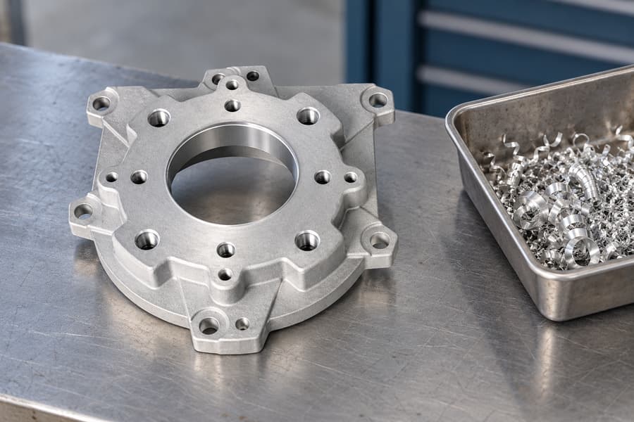
Removed gates, runners, risers, and machining chips should not automatically be classified as permanently lost material.
Suitable metal may be collected for recycling or remelting, depending on alloy requirements, cleanliness, and applicable production controls.
However, recovery involves segregation, handling, processing, and potentially remelting energy. Material losses and contamination can also affect the amount suitable for reuse.
Foundry yield should therefore be evaluated alongside scrap recovery and total production costs. Recyclable material retains potential value, but recovery does not create a zero-waste process.
What Determines the Total Cost of Near Net Shape Castings?
Near net shape casting becomes economically attractive when reductions in recurring processing costs outweigh any additional manufacturing requirements.
Shorter machining time alone does not guarantee lower total cost. Tooling, production volume, inspection, scrap recovery, and rejected components can change the economic outcome.
Tooling Investment and Production Volume
Complex casting geometry may require more elaborate patterns, dies, molds, or cores. These features can increase initial tooling investment.
Tooling cost per accepted component depends on production volume, useful tooling life, maintenance requirements, and the number of acceptable components produced.
For limited production quantities, additional tooling expense may outweigh modest reductions in machining time. Larger quantities can spread tooling investment across more components.
Tooling modifications must also be considered. Changes introduced to correct dimensional variation or feeding defects can alter the expected financial advantage.
Machining and Inspection Costs
Machining costs extend beyond the mass of material removed. They include machine occupancy, labor allocation, cutting tools, fixtures, maintenance, and secondary finishing.
Removing less stock can shorten cutting operations, but setup time may remain unchanged. A component requiring several precise interfaces may still need the same machining sequence.
Tool accessibility and cutting conditions also matter. A complex near net shape surface may need specialized tooling even when relatively little material remains.
Inspection requirements should be evaluated independently. Detailed cast features may require additional dimensional verification, while critical finished interfaces still need appropriate inspection.
Casting Quality, Reject Rates, and Rework
Geometry changes intended to reduce machining can affect casting process stability. Thin sections, complicated cavities, and challenging feeding paths may increase manufacturing difficulty.
Potential defects include shrinkage cavities, porosity, misruns, distortion, and dimensional nonconformance. Their occurrence depends on material, geometry, process conditions, and control effectiveness.
Rejected castings consume production resources even when their metal can be recovered. Machining-stage rejection may create additional losses because value has already been added.
Rework can restore certain components when technically permitted, but it adds processing and inspection costs. Unacceptable defects may require complete component rejection.
Comparisons must therefore consider both casting-stage and machining-stage acceptance rates. Lower machining stock is not beneficial if unacceptable components become substantially more frequent.
Comparing Total Cost per Accepted Component
A practical cost comparison should include the complete manufacturing route rather than evaluating casting and machining as unrelated operations.
Relevant cost categories include:
- Metal input: Material required for pouring, accounting for the selected material-cost and recovery model.
- Casting operations: Mold preparation, melting, pouring, solidification, removal, and related processing.
- Tooling allocation: Tool development, maintenance, replacement, and approved modifications.
- Machining and finishing: Equipment time, tools, fixtures, setup allocation, and additional operations.
- Quality control: Inspection, testing, and applicable documentation.
- Nonconformance: Rework, rejected components, handling, and disposal costs.
- Scrap recovery: Applicable recovery costs and credits without counting the same benefit twice.
The basic comparison can be expressed as:
Cost per accepted finished component = (Total relevant production costs − Applicable scrap recovery credits) / Number of accepted finished components
Scrap credits should be deducted only when their value has not already been reflected in material costs or internal remelt accounting.
A complete assessment should also consider how changes in production volume, tooling life, and acceptance rates affect the result.
Actual supplier quotations and representative production data are more reliable than generalized machining-savings assumptions. The preferred design is the one meeting specifications at an acceptable total cost.
Industrial Applications of Near Net Shape Casting
Near net shape design can be applied to many industrial cast components, particularly those combining complex geometry with a limited number of precision interfaces.
The following applications illustrate design opportunities rather than verified near net shape production results for specific Boberry Machining components.
Equipment and Pump Housings
Equipment housings often contain mounting bosses, ribs, cavities, and external profiles that can be formed directly during casting.
Producing these features close to their required dimensions may reduce external milling and material removal. Internal passages may also be formed using suitable cores.
Bearing seats, mating flanges, and sealing surfaces often require machining to maintain alignment and fit. Core positioning, wall thickness, and dimensional stability remain important design considerations.
Valve Bodies
Valve bodies frequently contain internal flow passages and external connection features. Casting these geometries can reduce the need to remove large volumes of material from solid blanks.
However, valve seats, precision bores, threaded interfaces, and sealing surfaces may require dedicated finishing operations.
Core positioning and internal soundness are particularly important where pressure containment or flow performance is involved. Inspection requirements should reflect the component’s intended service conditions.
Impellers
Impellers can contain curved blades, hub features, and flow passages that would be challenging to produce entirely through conventional material removal.
Casting may establish much of the blade geometry, leaving selected surfaces or interfaces for finishing.
Shaft mounting features require appropriate dimensional control. Surface condition, geometric consistency, and balancing requirements may also necessitate additional operations after casting.
For all three applications, the relevant question is which features can reliably remain as-cast without compromising functional requirements.
How to Validate a Near Net Shape Casting Design Before Production
Design calculations provide an initial basis for comparison, but representative manufacturing trials are needed to confirm casting quality, machining requirements, and total production economics.
Review Drawings and Manufacturing Requirements
The evaluation should begin with the finished component drawing. Critical dimensions, geometric tolerances, surface finishes, material specifications, and functional interfaces must be identified.
Each feature should be classified according to whether it can remain as-cast or requires finishing. This establishes the intended division between casting and machining operations.
Machining allowances and datum relationships should then be reviewed alongside feeding requirements, mold design, cores, and tooling accessibility.
Conduct Representative Casting and Machining Trials
Representative castings should be produced under controlled, documented conditions appropriate to the proposed manufacturing process.
Rough castings should be inspected for dimensions, stock distribution, surface condition, and relevant defects before machining begins.
Machining trials should verify complete cleanup of critical surfaces while meeting finished drawing requirements. Setup consistency and tool accessibility also require evaluation.
Actual cycle times, cutting-tool consumption, and inspection outcomes should be recorded. Results should reflect realistic operating conditions rather than isolated best-case measurements.
Verify Material Utilization and Production Economics
Material accounting should separately record total poured mass, removed gating and feeding material, usable rough casting mass, and machining chips.
Foundry yield and machining-stock reduction can then be calculated without confusing the different stages of material removal.
Casting acceptance and machining-stage acceptance should be measured separately. Both affect the quantity of metal and processing resources required per acceptable finished component.
Recovery values should reflect suitable scrap handling and reuse arrangements. Tooling allocation, inspection, rework, and rejection expenses must remain in the cost comparison.
The final production decision should be based on demonstrated dimensional conformity, casting soundness, process repeatability, and cost per accepted finished component.
A near net shape design is ready for production when its material and machining advantages remain worthwhile after the full manufacturing route has been validated.