
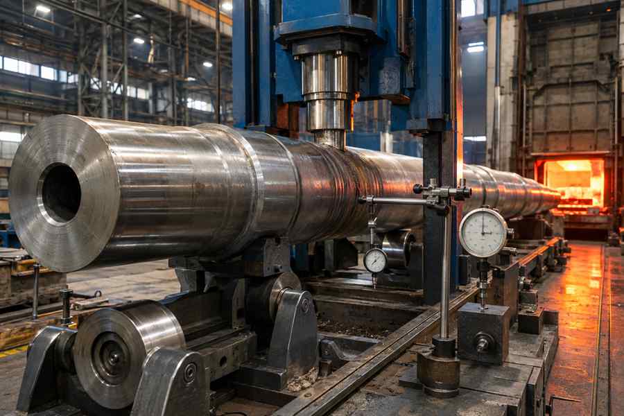
Large forged shafts are usually straightened through measured press correction, controlled heating, stress stabilization, and repeated runout inspection. The process must remove bending without creating cracks, hardness changes, or new residual stress.
Why Do Forged Shafts Bend After Heat Treatment?
A forged shaft may be straight after forging but bend during normalizing, quenching, tempering, or stress relieving. Uneven expansion and contraction can release internal stress and move the shaft away from its original centerline.
Common causes include:
- Uneven furnace temperature
- Different section thicknesses
- Improper furnace support
- Unbalanced quenching
- Rapid cooling on one side
- Residual forging stress
- Long length-to-diameter ratio
- Irregular material structure
Long and slender shafts are generally more sensitive than short, thick components. However, even heavy shafts can distort when journals, flanges, shoulders, or bore sections cool at different rates.
Key Steps in Large Forged Shaft Straightening
| Straightening Step | Main Control Point | Intended Result |
| Map the Shaft Runout | Measure high points, bend direction, and affected length | Identify the actual deformation |
| Select the Straightening Condition | Review material, hardness, shaft size, and heat-treatment state | Choose a safe correction method |
| Apply Press Straightening | Control support distance, force, and overbending | Correct moderate shaft curvature |
| Use Hot Straightening | Manage heating temperature and correction force | Reduce springback on hard or heavy sections |
| Stabilize Residual Stress | Control cooling, resting time, and further tempering | Prevent the bend from returning |
| Verify Straightness and Integrity | Recheck runout, hardness, and surface condition | Confirm the shaft is ready for machining |
1. Map the Shaft Runout
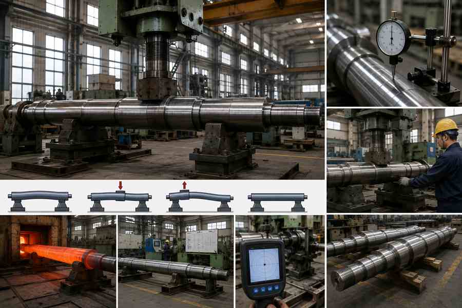
Straightening should begin with measurement rather than immediate press correction. The supplier needs to locate the high point, determine the direction of bending, and understand whether the deformation is local or spread across the shaft.
Measure on Rollers or Centers
The shaft is commonly supported on precision rollers, V-blocks, or machining centers and rotated slowly. Dial indicators or laser measuring systems record movement at several positions.
Typical measuring locations include:
- Main journals
- Shaft ends
- Shoulder areas
- Flange sections
- Diameter transitions
- Middle span
Measuring only the center may miss bends near a shoulder or journal. Long shafts should be checked along their complete working length.
Mark the Bend Direction
The highest indicator reading is marked directly on the component or recorded on an inspection chart. This identifies where corrective force should be applied.
Operators should also record:
- Total indicator reading
- Distance between supports
- High-point position
- Low-point position
- Bend length
- Shaft temperature during measurement
A clear runout map reduces unnecessary correction cycles and helps prevent force from being applied in the wrong area.
2. Select the Straightening Condition
The correction method depends on the shaft material, diameter, hardness, bend level, and remaining machining stock. Using the same procedure for every shaft can create cracks or unstable results.
Match the Method to the Material
Each steel category requires a different correction approach because its resistance to deformation is not the same. A hardened shaft usually has less deformation capacity than an annealed or normalized component.
The supplier should consider:
- Steel grade
- Current hardness
- Heat-treatment condition
- Shaft diameter
- Wall thickness for hollow shafts
- Location of section changes
- Required final straightness
In my view, hardness is often more important than shaft weight when choosing between cold and hot correction. A very hard shaft may resist movement and spring back even when the initial bend looks small.
Correct Before Final Machining
Straightening is normally completed before finish turning, grinding, or polishing. Enough surface stock should remain to remove small marks and restore final concentricity.
Correcting a finished shaft creates greater risk because press contact can damage:
- Bearing journals
- Sealing surfaces
- Threads
- Ground diameters
- Keyways
- Coated areas
Buyers should therefore specify rough and finished dimensions separately. This gives the supplier enough allowance for heat-treatment movement and final machining.
3. Apply Controlled Press Straightening
Hydraulic press straightening is widely used for moderate bending. The shaft is supported at two points while force is applied near the measured high point.
Use Three-Point Support
The support spacing should match the location and length of the bend. Supports placed too far apart may move an unnecessarily large shaft section, while narrow spacing can create concentrated stress.
The contact areas should be protected with suitable pads or shaped blocks. This prevents dents and distributes pressure more evenly across the surface.
The operator controls:
- Support position
- Press location
- Applied load
- Pressing time
- Number of correction cycles
- Shaft rotation between checks
Several small corrections are generally safer than one heavy press stroke. Gradual loading also makes the shaft response easier to predict.
Compensate for Springback
Steel partly returns toward its original shape after the press load is removed. The shaft must therefore be bent slightly beyond the target position.
The required overbending depends on:
- Material strength
- Hardness
- Shaft diameter
- Bend length
- Heat-treatment condition
- Previous correction cycles
Too little overbending leaves excessive runout. Too much can reverse the bend or introduce local stress, so each press cycle should be followed by measurement.
4. Use Hot Straightening for Hard or Heavy Sections
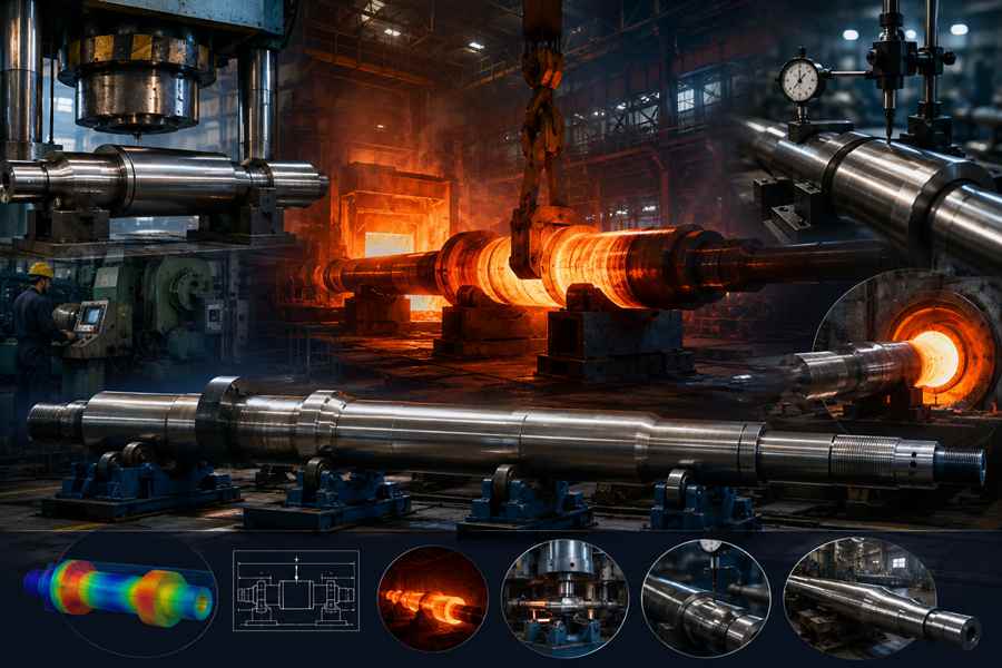
Hot straightening may be selected when cold correction requires excessive force or produces strong springback. It is especially useful for large diameters, hardened alloys, and shafts with heavy local sections.
Control the Working Temperature
The shaft may be heated in a furnace or corrected during a suitable tempering stage. The temperature must remain within an approved range for the specific steel and heat-treatment condition.
Controlled heating can:
- Lower straightening force
- Reduce springback
- Improve deformation ability
- Limit cracking risk
- Make correction more stable
Temperature records should be included for critical components. Straightening at an unknown temperature can affect hardness, strength, and microstructure.
Prevent Local Overheating
Direct flame heating can create steep temperature differences if it is not carefully controlled. A small overheated zone may expand rapidly and introduce another bend after cooling.
The supplier should control:
- Heating location
- Heating area
- Maximum temperature
- Temperature difference
- Holding time
- Cooling method
For high-load shafts, uniform furnace heating is generally more predictable than uncontrolled local flame correction. Local heating should only be used with a documented procedure.
5. Stabilize Residual Stress
A shaft may appear straight immediately after pressing but move again after several hours or during machining. This happens when residual stress has not fully stabilized.
Cool and Rest the Shaft
After hot correction, the component should cool uniformly while properly supported. Uneven airflow or contact with a cold surface may recreate distortion.
The shaft is then allowed to rest before final measurement. This waiting period helps reveal whether the correction remains stable after the applied force and temperature are removed.
The supplier should avoid:
- Rapid cooling on one side
- Unsupported long spans
- Uneven storage surfaces
- Immediate finish machining
- Lifting from a single point
Large components should also be handled with suitable lifting positions. Poor handling can bend a long shaft even after successful straightening.
Repeat Tempering When Required
Some shafts require an additional tempering or stress-relief cycle after mechanical correction. This reduces internal stress but may also cause slight dimensional movement.
The decision depends on:
- Material specification
- Final hardness
- Correction amount
- Service load
- Customer standard
- Inspection requirements
When further heat treatment is used, straightness must be checked again afterward. An inspection completed before the final cycle does not confirm the delivered condition.
6. Verify Straightness and Integrity
The shaft should pass dimensional and material checks before entering finish machining. Straightness alone is not enough if correction has damaged the surface or changed the required properties.
Recheck Runout
The shaft is returned to rollers, centers, or a measuring fixture and rotated again. Indicators are placed at the same locations used during the initial inspection.
The final report may include:
- Runout at each journal
- Overall straightness
- Centerline deviation
- Shaft length
- Support locations
- Measurement temperature
- Drawing tolerance
For machined shafts, buyers should distinguish between straightness and journal runout. A straight shaft can still show runout if diameters are not concentric.
Confirm Hardness and Surface Quality
Critical shafts may need hardness testing and nondestructive examination after correction. This helps identify surface cracking or property changes caused by pressing and heating.
Possible inspections include:
- Visual inspection
- Magnetic particle testing
- Ultrasonic testing
- Dye penetrant testing
- Hardness testing
- Dimensional inspection
The inspection method should match the material and application. Shafts used in turbines, rolling mills, marine systems, or heavy transmissions normally need stricter verification than general mechanical parts.
Stable Straightening Requires Final Verification
Reliable correction depends on several connected controls:
- Accurate bend location
- Suitable working temperature
- Controlled press force
- Springback compensation
- Residual stress stabilization
A shaft may meet tolerance after pressing but move again during cooling or machining. Final acceptance should include:
- Stabilization time
- Repeated runout measurement
- Hardness testing when required
- Surface crack inspection