
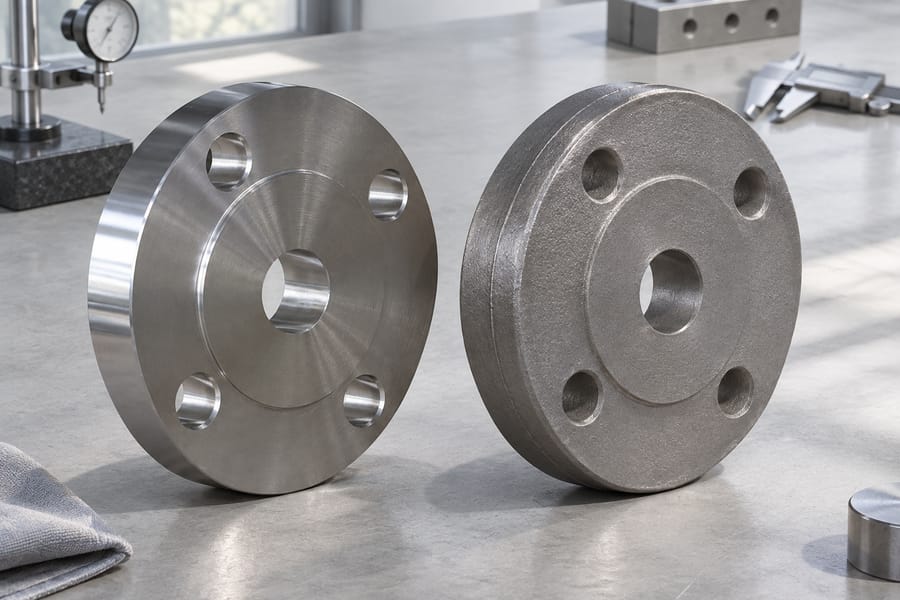
Forged steel flanges and cast steel flanges perform similar piping functions, but their manufacturing routes create different material structures, inspection needs, and production options under service conditions.
A fair comparison considers equivalent alloys, heat-treatment conditions, product specifications, service loads, joint design, machining requirements, and documented acceptance requirements for the specified service and operating conditions.
What Are Forged Steel Flanges and Cast Steel Flanges?
Forged Steel Flanges
A forged steel flange begins with solid steel stock, commonly a billet or another suitable starting form. The material is heated to a workable condition and shaped by compressive force from a hammer or press.
During deformation, steel flows to fill the forming space. Stock orientation, temperature, and forming sequence influence the structure and material distribution around the flange hub, body, and rim.
Forged flanges are produced in configurations such as weld-neck, slip-on, and blind designs. The selected configuration still needs to match the piping layout, connection method, applicable standard, and loads expected at the joint.
From Melt to Flange Blank
For a cast flange, the starting shape develops as liquid steel freezes inside the mold.
The metal fills the cavity, cools, and solidifies into a shape that can then undergo cleaning, heat treatment where required, and machining.
A mold can accommodate shapes that may require more involved forging operations. The resulting structure depends on melt quality, mold design, filling, cooling, and any subsequent heat treatment.
Cast steel is not cast iron. Both are cast materials, but they are different material families with different compositions, specifications, and mechanical characteristics.
A purchase description should identify cast steel and its required grade rather than using the terms interchangeably.
Forging vs Casting: Key Manufacturing Differences
Solid-State Deformation Compared with Solidification
The central distinction is the state of the metal during shaping. Forging deforms solid steel under compressive loads; casting shapes liquid steel by allowing it to solidify inside a mold.
Forging deformation can elongate and redirect the existing material structure. With suitable process design, grain flow may follow the component’s general contour, depending on starting stock and forming sequence.
Casting does not create forged grain flow. Instead, the metal develops a solidification structure as crystals form and grow during cooling. Local conditions can vary across a thick hub, thin rim, or transition section.
Neither process description establishes suitability by itself. The result depends on alloy, geometry, process controls, heat treatment, machining, inspection, and the order’s acceptance requirements.
Practical Differences in Production
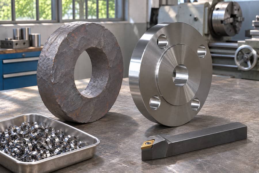
Forging may involve billet preparation, heating, one or more forming operations, trimming, heat treatment, and machining. The process must provide sufficient deformation in the relevant regions without creating laps, folds, or other discontinuities.
Casting involves melting, mold preparation, pouring, solidification, removal from the mold, cleaning, and any specified heat treatment. The foundry process must control filling and cooling so that the casting meets its required quality level.
Both routes normally require machining of critical features. Raised faces, bores, bolt holes, and interfaces must meet the drawing and governing dimensional requirements.
| Comparison factor | Forged steel flange | Cast steel flange |
| Metal condition during shaping | Solid steel is plastically deformed | Molten steel fills a mold and solidifies |
| Structure formed | Deformed structure with process-dependent grain flow | Solidification structure influenced by cooling conditions |
| Geometry considerations | Influenced by stock, tooling, forming sequence, and machining | Influenced by mold design, filling, solidification, and machining |
| Potential discontinuities | Laps, folds, cracks, and inclusions | Shrinkage, porosity, inclusions, and hot tears |
| Key process controls | Stock quality, heating, deformation, and heat treatment | Melt quality, mold condition, filling, cooling, and heat treatment |
| Final dimensional control | Machining and inspection against the drawing and standard | Machining and inspection against the drawing and standard |
Mechanical Properties: Strength, Toughness, and Fatigue
Tensile and Yield Strength
Tensile strength is the maximum stress reached during a tensile test; yield strength marks the specified onset of permanent deformation. Both must be evaluated against the applicable specification.
Alloy and heat treatment affect these values. Section thickness, sampling location, product form, and test method also matter when comparing certificates or qualification data.
A forged flange should not be assumed to exceed a cast flange in strength simply because it was forged.
The meaningful comparison is between products made from equivalent alloy grades and evaluated in the required condition under comparable test requirements.
A cast steel flange should not be rejected solely because it was cast. It may be suitable when its grade, heat treatment, test results, and acceptance requirements meet the defined service.
Toughness, Ductility, and Fatigue
Toughness concerns a material’s ability to absorb energy before fracture, while ductility describes its capacity for plastic deformation. These properties are related but not interchangeable, and neither can be inferred from tensile strength alone.
Where impact testing applies, confirm the material specification, product form, test temperature, and specimen location. A different sampling position or test setup can change what the figures mean, so check these details before comparing certificates.
Fatigue performance becomes important when a flange experiences repeated pressure cycles, vibration, thermal cycling, or fluctuating external loads. Local stress concentrations around bolt holes, hub transitions, weld ends, and surface marks can influence crack initiation.
Discontinuities can affect fatigue, depending on their type, size, orientation, location, and applied stress. An indication in a low-stress region may have a different significance from one near a loaded transition.
For cyclic service, review design loads, flange geometry, material condition, surface finish, and inspection findings together. Manufacturing route is not a standalone fatigue rating.
Making a Fair Mechanical Comparison
Compare the same or technically equivalent alloy grades, heat-treatment conditions, product specifications, and test requirements. If the material grades differ, observed property differences cannot confidently be attributed to forging or casting alone.
Check where test specimens were removed and whether their orientation represents the critical flange section. Product specifications may define sampling and testing rules that differ by product form, so certificate values need context.
For demanding service, establish required properties through the design code, project specification, and engineering assessment rather than a general claim about either manufacturing route.
Manufacturing Discontinuities and Non-Destructive Examination
What Can Occur in Forged Flanges?
Forging can produce laps or folds when material folds over and forms an unbonded overlap. Poorly controlled heating or deformation may also contribute to cracking, while inclusions can originate in the starting steel.
Surface cracks may appear during forming, trimming, or machining. Internal discontinuities may require an appropriate examination method when the specification or application calls for one.
Process control reduces risk but does not make every forging defect-free. Starting-stock quality, forming, heat treatment, and inspection all affect acceptance.
What Can Occur in Cast Flanges?
Castings can contain shrinkage cavities where metal contraction is not adequately fed during solidification. Gas porosity, nonmetallic inclusions, and hot tears are other possible discontinuities associated with melting, mold filling, and cooling.
Location matters: a subsurface indication in a highly stressed hub may be assessed differently from one in a less critical region, subject to the acceptance criteria.
Good casting practice and inspection can control risk. Geometry and section thickness should inform method selection because they affect detection of particular conditions.
Planning Examination Coverage
Begin with a visual review of accessible surfaces, including any damage left by handling or machining. Penetrant examination targets openings that reach a clean surface. For ferromagnetic grades, magnetic particles can indicate surface flaws and some flaws immediately below it.
Ultrasonic testing examines internal regions, although geometry, grain structure, access, and material characteristics affect coverage. Radiographic testing can reveal certain internal conditions, subject to section thickness, geometry, defect orientation, and procedure.
No single NDE method detects every discontinuity. The purchase specification should identify the required method, examination extent, location, reporting requirements, and acceptance criteria rather than merely stating that inspection is required.
Acceptance criteria should come from the governing specification, code, or project document. An examination report records the inspection result; it does not guarantee a discontinuity-free component.
Material Specifications, ASME Standards, and Pressure Class
Separate Material Requirements from Flange Dimensions
ASTM material and product specifications define requirements for particular steel products, which may include grade, manufacturing condition, heat treatment, mechanical testing, and other acceptance provisions. The exact specification must suit the flange’s product form.
ASME flange standards address dimensions, pressure-temperature ratings, facing details, and related requirements within their stated scope. They do not replace the need to specify the correct material or product specification.
For example, a purchase order should not rely on a general description such as carbon steel flange. It should identify the required material grade and product specification, along with the applicable flange standard and designation.
Understand Class and Pressure-Temperature Ratings
A flange Class designation is not a pressure value in pounds per square inch. Read the rating table for the specified material group at the design temperature; use the table belonging to the flange standard invoked by the project.
Changing a flange blank from cast to forged does not automatically raise the rating of a standard flange. The finished product must comply with the applicable dimensional and pressure-temperature requirements for its specified material and designation.
ASME B16.5 and ASME B16.47 cover different flange size and configuration scopes. Select the applicable standard by flange type, nominal size, and project requirements.
Verify facing, nominal pipe size, bolt pattern, bore, and permitted dimensional options. Correct material does not make a flange with incompatible dimensions or facing interchangeable.
Machining and Flange-Joint Integrity
Machining the Finished Flange
Forged and cast blanks both require machining where the design specifies finished bores, bolt holes, raised faces, or other precision interfaces. The machining plan should account for the blank’s geometry and the material available for removal.
Check critical dimensions against approved drawings and the governing standard, including bore, thickness, facing, bolt-hole location, and relevant geometric relationships.
Machining can expose a discontinuity that was not visible on the original surface. If this occurs, the indication should be evaluated under the applicable acceptance requirements rather than automatically removed or ignored.
Define custom bore dimensions, bolt-circle details, facing, and connection type on the drawing or purchase specification so the supplier can quote the intended part.

Facing, Gaskets, and Bolting
The flange face must suit the gasket and joint design. Facing and surface finish affect contact and should be specified with gasket material, service fluid, and assembly method in mind.
Select gaskets for fluid compatibility, pressure, temperature, facing, and required sealing behavior. An unsuitable gasket can compromise a joint even when flange dimensions are correct.
Bolting also contributes to joint performance. Bolt material, size, lubrication condition, tightening sequence, and applied preload influence the clamp load available to compress the gasket and resist operating loads.
Uneven tightening, misalignment, external loads, or inadequate support can disturb the joint. Manufacturing route cannot compensate for an unsuitable gasket, incorrect bolting, or poor installation.
Do not attribute leakage to forging or casting without examining the assembly, including flange faces, gasket condition, bolt preload, alignment, operating cycles, and installation procedure.
Cost and Procurement Considerations
What Drives the Cost of Each Route?
Forged flange cost can reflect starting-stock grade, billet dimensions, heating, forming operations, tooling, trimming, heat treatment, machining allowance, and inspection. The amount of material removed during finishing can also affect yield.
Cast flange cost can reflect alloy and melt requirements, mold preparation, pouring, solidification controls, cleaning, heat treatment, machining, and examination. Complex geometry may suit a casting route, but quality requirements can add process and inspection work.
Production quantity changes the economics of both methods. Tooling, setup, material availability, and machining can shift the comparison between small and large orders.
There is no universal lower-cost route. Compare equivalent finished requirements for material, dimensions, machining, inspection, documentation, packaging, and acceptance activities.
Evaluate Total Accepted-Part Cost
The lowest initial unit price may not represent the lowest procurement cost if the product requires extra machining, additional inspection, rework, or replacement after failing acceptance. Conversely, a more involved manufacturing route is not automatically justified.
Buyers should compare quotations against one controlled technical specification. If one supplier prices a different material condition, inspection extent, facing, or documentation package, the quoted prices do not describe equivalent products.
Assess lead time against the production route, material availability, tooling status, and inspection scope; neither method is always faster for every geometry or order quantity.
Choosing a Flange and Preparing a Practical RFQ
Match the Manufacturing Route to the Application
Forged steel may be a suitable choice where the specified product form, deformation characteristics, and available manufacturing route align with the design requirements. Approval still needs a documented link between the flange supplied, its specified metallurgical condition, and the inspection records.
Cast steel may be suitable where the geometry and production plan favor molding and the finished casting can meet the specified material, mechanical, dimensional, and inspection requirements.
Casting should be judged against its acceptance criteria, not dismissed categorically.
For either route, define the service fluid, design pressure and temperature, minimum design temperature where relevant, cyclic loading, external forces, corrosion, and welding requirements. These conditions guide material and product selection.
Where installation includes welding, confirm material weldability, applicable welding procedure requirements, and any specified preheat or post-weld treatment.
Confirm flange configuration and joint details. Weld-neck, slip-on, and blind designs serve different connection purposes; facing, gasket, bolting, bore, and bolt pattern must match the piping design.
What to Include in the Request for Quotation
A clear RFQ lets suppliers assess the product without guessing. Attach an approved drawing and distinguish mandatory requirements from preferences.
- Material: State the alloy grade, ASTM material or product specification, and required heat-treatment condition.
- Flange standard: Identify the applicable ASME standard, nominal size, Class designation, facing, and flange configuration.
- Dimensions: Provide bore, outside dimensions where not controlled by the standard, thickness, bolt-circle details, and any nonstandard features.
- Service: Describe fluid, design pressure, design temperature, minimum temperature where relevant, cyclic duty, corrosion conditions, and external loads.
- Manufacturing route: State whether forging or casting is required, or identify whether an approved alternative may be considered.
- Examination scope: Name the methods to be used, the areas to be examined, the pass/fail basis, and the reports required with delivery.
- Testing and records: Identify required mechanical tests, material traceability, reports, and documentation under the governing specification.
- Machining: Define finished bore, bolt holes, flange face, surface finish, and dimensional inspection requirements.
- Delivery scope: State quantity, required delivery location, preservation, marking, and packaging expectations.
Boberry Machining offers forged flange families in carbon, stainless, alloy, and duplex steel, with weld-neck, slip-on, blind, and other connection types. Available customization includes multiple facings and machining of bores, bolt circles, and flange faces.
Check that the quotation matches the RFQ for material, manufacturing route, configuration, machining, and inspection. Resolve deviations in writing before production.
| RFQ item | Information to define before ordering |
| Material and condition | Grade, product specification, heat treatment, and required mechanical properties |
| Standard and rating | Applicable ASME standard, size, Class, material group, and design temperature basis |
| Joint configuration | Flange type, facing, gasket compatibility, and bolting requirements |
| Critical dimensions | Bore, bolt circle, hole arrangement, face dimensions, and drawing revisions |
| Quality requirements | Inspection methods, coverage, acceptance criteria, test requirements, and records |
| Commercial scope | Quantity, machining extent, packaging, marking, delivery location, and approved deviations |
Before release, ensure the purchase order, drawing, material specification, and inspection plan describe the same finished product.