
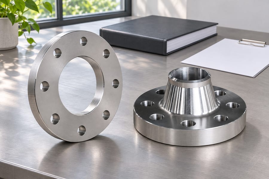
Forged flange standards define dimensions, materials, pressure-temperature ratings, and joint details. ASME, ANSI, DIN, and EN have different roles in developing, approving, and adopting these requirements; their designations are not interchangeable.
Engineers and buyers must identify the governing document and edition, then verify size, grade, facing, design conditions, and mating dimensions before specifying or purchasing a flange.
What ASME, ANSI, DIN, and EN Mean in Flange Standards
ASME, ANSI, DIN, and EN frequently appear in industrial piping specifications, but they do not represent four equivalent flange design systems. Understanding their respective roles helps engineers identify the actual technical requirements behind a flange designation.
Who Writes the B16 Requirements
For the B16 series, technical authorship rests with ASME. Its broader engineering publications also deal with machinery and the design of systems that contain pressure. Its B16 standards establish technical requirements for different types of piping components.
Two particularly relevant documents for forged steel flanges are ASME B16.5 and ASME B16.47. They define dimensional requirements, pressure-temperature ratings, tolerances, materials, marking, and other requirements within their respective scopes.
ASME B16.5 addresses standard pipe flanges across a broad range of nominal sizes, while B16.47 addresses larger-diameter steel flanges. Both provide a technical basis for specifying flange dimensions and pressure classes.
What ANSI Approval Signifies
ANSI’s contribution is oversight of the voluntary standards framework in the United States. It accredits standards developers and approves eligible documents as American National Standards through established procedures.
ANSI does not independently write the technical requirements contained in ASME B16.5. ASME develops the flange standard, while ANSI’s role relates to the national standards approval and accreditation framework.
This distinction explains why engineers sometimes encounter ANSI/ASME references in technical documents. The presence of ANSI in a designation does not indicate a separate flange dimensional system with independent bolt patterns or pressure ratings.
For procurement purposes, identifying the actual technical document, such as ASME B16.5, is more useful than specifying an ANSI flange without further clarification.
DIN and EN: German and European Standardization
DIN is Germany’s national standards organization, responsible for coordinating and publishing German standards. EN refers to European Standards developed through recognized European standardization organizations, including the European Committee for Standardization (CEN).
When a European Standard is adopted as a German national standard, its designation commonly receives the DIN EN prefix. For example, DIN EN 1092-1 identifies the German adoption of EN 1092-1.
This prefix does not establish a separate German flange geometry. The underlying European technical requirements remain the basis of the adopted document.
However, standalone DIN documents and older national standards must not automatically be treated as identical to current EN requirements. Their technical scope, publication status, and dimensional provisions need individual verification.
ASME Forged Flange Standards: B16.5 vs. B16.47
ASME B16.5 and B16.47 are two important references for forged steel flange dimensions and pressure-temperature ratings. Their principal distinction is the nominal size range and the dimensional systems used for their respective applications.
The Size Range Addressed by B16.5
For pipe flange and flanged-fitting orders, B16.5 is the relevant starting document when the nominal designation falls between NPS 1/2 and NPS 24.
The rating tables distinguish seven Class designations, starting at 150 and extending to 2500; intermediate designations are 300, 400, 600, 900 and 1500.
These Class designations identify pressure-rating categories within the standard rather than direct pressure values in psi. The applicable allowable pressure depends on the specified material group and temperature.
An important size limitation applies to Class 2500: it is available only through NPS 12. Therefore, engineers should not assume that every B16.5 pressure class covers the entire NPS 1/2–24 range.
The standard establishes several dimensional characteristics that determine whether a flange can connect correctly with its intended mating component:
- Outside diameter and thickness: Define the flange’s external envelope and overall dimensional arrangement.
- Bolt-circle diameter: Establishes the circular positioning of the connecting bolt holes.
- Bolt-hole arrangement: Specifies the number, diameter, and positioning requirements for bolting.
- Bore and hub dimensions: Determine the internal opening and relevant connection geometry.
- Facing dimensions: Define the applicable raised face, flat face, or other permitted sealing configuration.
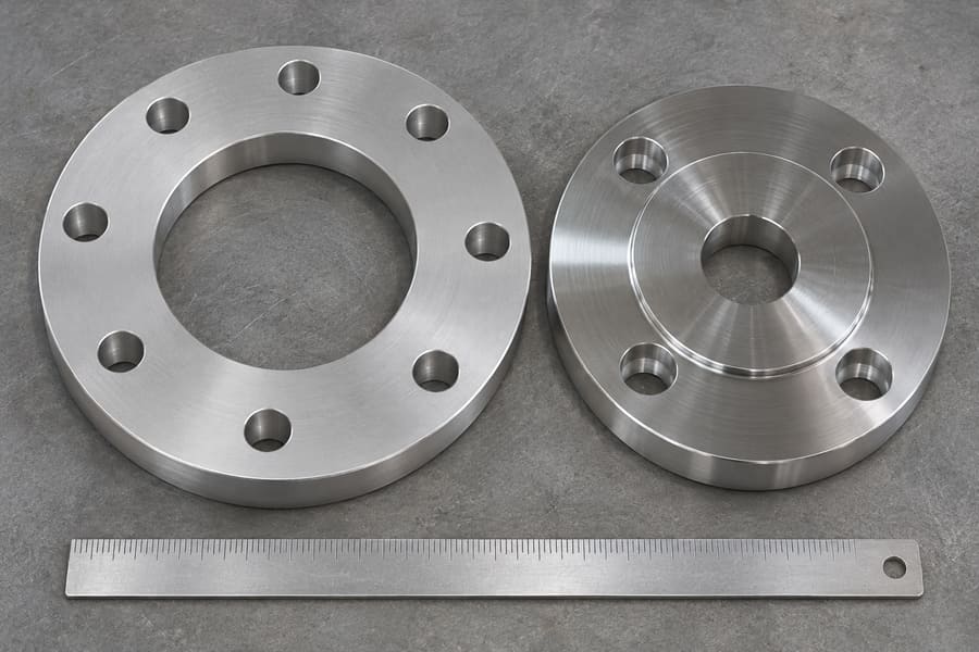
B16.5 covers different flange configurations, including weld-neck, slip-on, and blind flanges, along with other types within its scope. The selected configuration determines which dimensional and connection requirements must be checked.
For example, a weld-neck flange requires attention to its hub and bore arrangement, particularly where the connecting pipe has a specified wall thickness. A blind flange instead requires verification of its closure geometry and mating-face dimensions.
Moving Beyond the B16.5 Size Range
For steel flange orders from NPS 26 upward, B16.47 provides the large-bore dimensional framework, with its scope extending to NPS 60. It provides dimensional and rating requirements for applications beyond the upper size range of B16.5.
The standard includes two dimensional series, Series A and Series B. These series have different flange dimensions and bolting arrangements, so the series designation is an essential part of the specification.
Series A generally uses larger and heavier flange configurations than corresponding Series B designs. Series B provides a more compact dimensional arrangement for applicable applications. Their differences affect bolt-circle dimensions, bolt quantities, flange proportions, and equipment interfaces.
B16.47 includes Class designations such as 75, 150, 300, 400, 600, and 900, subject to the applicable series and size provisions. Engineers must consult the relevant tables rather than assume every designation applies to every combination.
For procurement, specifying only NPS and Class is insufficient when the selected B16.47 series has not been identified. Matching the size and Class on an order does not ensure that the holes will line up or that the two sealing surfaces will fit.
How to Distinguish B16.5 and B16.47
The nominal size ranges provide the first distinction. B16.5 covers NPS 1/2–24, whereas B16.47 covers NPS 26–60.
However, the decision involves more than identifying which document covers a particular size. The engineer must also verify the applicable pressure class, material, flange type, facing, and equipment connection requirements.
For large-diameter applications, the Series A or Series B designation must be included explicitly. This prevents purchasing teams from assuming that two flanges described only by nominal size and Class will share the same dimensional arrangement.
European Flange Standards: EN 1092-1 and DIN EN
European flange specifications commonly use DN and PN designations. EN 1092-1 provides a principal reference for circular steel flanges, establishing requirements that differ in structure and designation from the ASME B16 standards.
EN 1092-1: Steel Flange Requirements
EN 1092-1 covers circular steel flanges used with pipes, valves, fittings, and related equipment. Its requirements address flange types, dimensions, tolerances, facings, materials, marking, and pressure-temperature relationships.
Unlike the NPS system used by ASME B16.5 and B16.47, EN 1092-1 uses nominal diameter designations identified as DN. Its pressure designation system uses PN rather than ASME Class.
The standard includes different flange configurations, such as welding-neck, plate, blind, and other applicable types. Each configuration has specific dimensional requirements that influence its connection with the pipeline or equipment.
Important dimensional considerations include flange outside diameter, thickness, bolt-hole arrangement, bore, facing geometry, and applicable tolerances. These details determine the physical interface between connecting components.
Facing requirements also matter because the flange must accommodate the intended gasket arrangement. The sealing surface, dimensions, and relevant machining requirements should follow the selected standard and project specification.
Material provisions establish requirements for the steel grades permitted within the standard’s scope. The exact material selection must still account for the applicable grade, service conditions, and project requirements rather than relying on PN alone.
DIN EN vs. Standalone DIN Standards
DIN EN 1092-1 is the German national adoption of EN 1092-1. The technical foundation is the European Standard, not an independently developed German flange geometry.
This distinction becomes important when reviewing older drawings, equipment documentation, and procurement records. A drawing that references a standalone DIN document may not necessarily describe the same dimensions as a newer DIN EN specification.
Engineers should therefore identify the complete document number and publication edition. Where a project specifies a particular national adoption, that reference should be retained in the technical documentation.
For procurement teams, using the phrase DIN flange without an exact standard reference creates unnecessary uncertainty. The supplier needs to know which dimensional document governs the finished flange and which material requirements apply.
ASME, ANSI, DIN, and EN: Main Differences Compared
The following comparison summarizes the principal roles and flange references. It also highlights why ANSI should not be treated as an independent dimensional standard alongside ASME B16.5 or EN 1092-1.
| Reference | Main role or document | Size designation | Pressure designation | Key consideration |
| ASME B16.5 | Standard pipe flange requirements | NPS | Class | Verify dimensions, Class, material, and facing. |
| ASME B16.47 | Large-diameter steel flange requirements | NPS | Class | Specify Series A or Series B. |
| ANSI | Standards accreditation and approval framework | Depends on the underlying standard | Depends on the underlying standard | Identify the actual technical document. |
| EN 1092-1 | European steel flange standard | DN | PN | Verify applicable dimensions and pressure-temperature requirements. |
| DIN EN 1092-1 | German adoption of EN 1092-1 | DN | PN | Confirm the underlying EN document and edition. |
| Standalone DIN | Specific German national standard | Document-dependent | Document-dependent | Check the exact DIN reference and its requirements. |
Why These Flange Standards Are Not Automatically Interchangeable
The main compatibility issue is that nominal size and pressure designation do not fully describe the physical flange interface. Different standards can establish different dimensions for components serving similar piping applications.
For example, two flanges with corresponding nominal sizes may have different outside diameters, thicknesses, bolt-circle diameters, or bolt-hole arrangements. These differences can prevent direct connection even when their nominal designations appear similar.
Facing geometry introduces another consideration. A raised-face flange, flat-face flange, and ring-type-joint flange require different mating arrangements and gasket interfaces.
Pressure designations create a separate source of confusion. ASME Class and EN PN belong to different rating systems, with their own material and temperature relationships. Similar-looking designations do not establish equivalent allowable pressures.
Consequently, a flange substitution requires engineering verification of both dimensional compatibility and pressure-temperature suitability. A simple nominal-size match or pressure designation conversion cannot establish that the proposed component meets the original design requirements.
Four Essential Elements of a Complete Forged Flange Specification
A forged flange specification combines several technical requirements that serve different purposes. Separating these elements helps engineers prepare accurate drawings and prevents procurement teams from treating one designation as a complete product specification.
Dimensional Standard: Flange Geometry and Nominal Size
The dimensional standard determines the flange geometry and the reference requirements for its nominal size, pressure designation, configuration, and relevant dimensions.
NPS and DN are nominal identification systems rather than direct measurements of a flange’s bore or outside diameter. Their relationship must be established through the applicable standard’s dimensional tables.
For instance, an NPS designation should not be interpreted as the actual flange bore. The bore depends on the specified configuration and relevant connecting-pipe dimensions.
The dimensional specification should identify the standard, nominal size, pressure designation, flange type, and facing. Where additional machining is required, the drawing should define the relevant dimensions and tolerances.
For large-diameter B16.47 flanges, the Series A or Series B designation must also be included. Without it, the dimensional reference remains incomplete.
Material Specification: Steel Grade and Forging Requirements
The material specification identifies the steel grade and associated material requirements. It is separate from the dimensional standard, even though both documents contribute to the finished flange specification.
ASTM A105 is an example of a carbon steel forging specification commonly referenced for forged piping components. For alloy or stainless grades, A182 is a separate material reference used for qualifying forgings and certain rolled products intended for piping service at elevated temperature.
Depending on the applicable grade and project requirements, material selection may involve carbon steel, stainless steel, alloy steel, or duplex stainless steel. These material families have different mechanical and corrosion-related characteristics.
A carbon grade is a candidate only after its strength requirements and the proposed protection against corrosion have been checked for the particular duty. Stainless steel is often evaluated where corrosion resistance is an important selection factor.
Alloy steels may be specified for particular temperature, strength, or service requirements. Duplex stainless steels may be considered where the required combination of mechanical properties and corrosion resistance supports their use.
However, identifying a material family alone is insufficient. Procurement documents should specify the exact grade and governing material specification, including any required heat-treatment condition and supplementary requirements.
Material availability also depends on the selected standard, grade, nominal size, manufacturing requirements, and project specification. Engineers should verify that the proposed material is permitted for the intended flange application.
Pressure-Temperature Rating: Understanding Class and PN
ASME Class and EN PN identify different flange pressure-rating systems. Neither should be interpreted as a direct measurement of allowable working pressure under every operating condition.
ASME Class 150, for example, does not mean that a flange has a universal allowable pressure of 150 psi. The applicable rating depends on the material group and temperature provisions in the governing standard.
Similarly, PN is a nominal pressure designation rather than a universal guarantee that the allowable pressure equals the stated number of bar at every temperature. The relevant EN rating provisions must be consulted.
Engineers should distinguish design pressure and design temperature from ordinary operating readings. Design conditions form part of the engineering basis for selecting piping components and should not be replaced by normal day-to-day gauge readings.
Where operating conditions fluctuate, the responsible engineering design should account for relevant process cases, including applicable transient or upset conditions. The selected flange rating must satisfy the governing design basis.
Pressure-temperature tables should therefore be checked using the exact material group, applicable class or PN designation, and design temperature. A conversion chart alone cannot establish equivalent suitability between ASME and EN systems.
Assembly Requirements: Bolting, Gaskets, and Mating Faces
A flange’s dimensional and pressure designation does not independently define every requirement for the completed bolted joint. The connecting components and assembly method also influence joint suitability.
Bolting selection should account for the specified bolt material, dimensions, quantity, and arrangement. These details must match the flange geometry and the applicable project requirements.
Gasket selection depends on the facing configuration, service fluid, design temperature, design pressure, and joint requirements. The gasket must fit the intended sealing interface rather than simply match the nominal pipe size.
Flange alignment and sealing-face condition also deserve attention during installation. Misalignment or unsuitable surface conditions can interfere with proper gasket seating and joint assembly.
Bolt-tightening procedures should follow the applicable engineering and project requirements. The required assembly method should not be inferred solely from the flange’s pressure class or nominal diameter.
Forged Flange Types, Facing Options, and Compatibility
Flange type and facing describe different aspects of a flange. The type defines its connection configuration, while the facing identifies the geometry of the surface intended to form the gasket interface.
Common Forged Flange Connection Types
Weld-neck flanges:
These flanges have a hub designed for connection to a pipe through butt welding. Their bore and welding-end dimensions must correspond to the intended pipe and applicable drawing requirements.
Slip-on flanges:
These flanges fit over the connecting pipe before welding. Pipe insertion, alignment, bore dimensions, and the specified welding arrangement are relevant when checking the connection.
Blind flanges:
These components close the end of a piping system or an equipment connection. Their selection requires attention to pressure-temperature suitability, thickness, bolt arrangement, and mating-face geometry.
Other configurations:
Threaded, socket-weld, lap-joint, and other flange types may be specified where permitted by the governing standard and application. Their connection details must be checked against the relevant technical provisions.
RF, FF, and RTJ Facing Types
Raised Face (RF), Flat Face (FF), and Ring Type Joint (RTJ) are three common facing designations. Their different geometries determine the corresponding gasket arrangement and mating-surface requirements.
RF geometry:
Around the flow opening, a narrow annular land stands above the surrounding metal. The gasket is positioned against this defined surface, so its dimensions and compatibility must match the flange arrangement.
Flat Face (FF):
An FF flange has a flat mating surface extending across the flange face. Its gasket contact arrangement differs from RF, and the connecting component must be suitable for the specified flat-face joint.
Ring Type Joint (RTJ):
An RTJ flange has a machined groove designed to accommodate a compatible metal ring gasket. The groove geometry and ring-gasket profile must correspond to the specified joint arrangement.
Facing selection should reflect the equipment interface and project requirements. A flange should not be changed from RF to FF or RTJ merely because its nominal size and pressure designation remain unchanged.
Surface finish is another important consideration. The specified machining condition must be consistent with the governing standard, facing type, and gasket requirements. Where a project defines additional surface requirements, these should appear on the drawing.
Critical Dimensions for Flange Matching
Physical compatibility depends on several dimensions considered together. Checking only the flange outside diameter or nominal size may overlook differences that prevent correct assembly.
- Outside diameter and thickness: Confirm the overall dimensions against the mating flange or equipment drawing.
- Bolt-circle diameter: Verify that the connecting bolt centers align with the corresponding component.
- Bolt-hole layout: Check hole quantity, diameter, and angular positioning.
- Bore and hub: Match the internal opening and connection geometry to the intended pipe arrangement.
- Facing dimensions: Verify the sealing-surface configuration and gasket contact area.
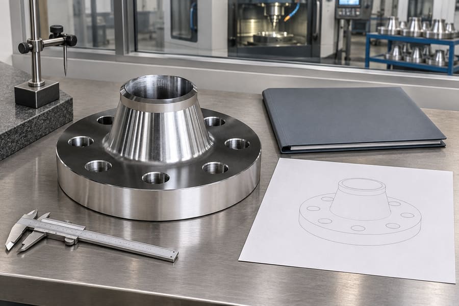
For weld-neck flanges, the bore and welding-end geometry deserve particular attention because they relate directly to the connecting pipe. Pipe schedule and wall thickness should be considered when defining the required internal dimensions.
How to Select the Correct Forged Flange Standard
Flange selection should begin with the governing project requirements rather than a supplier’s general product description. Reviewing the drawing together before the purchase order is issued prevents engineering and purchasing from working to different references.
Identify the Governing Project Requirements
First, identify the applicable piping design code, project specification, and installation jurisdiction. These requirements establish which flange standards and material specifications are acceptable for the intended system.
Existing equipment connections should also be reviewed. Replacement flanges must match the actual interface requirements, which may involve an existing standard, a specific dimensional series, or approved project modifications.
Where project documents specify a particular standard edition, that edition should be recorded in the purchase specification. A newer publication should not be substituted automatically without checking project approval requirements.
Verify Size, Pressure, Temperature, and Material
Confirm whether the project uses NPS or DN, then identify the corresponding nominal size under the selected standard. Actual flange dimensions should come from the applicable standard tables and approved drawings.
Next, establish the required ASME Class or EN PN designation. The selection must be checked against design pressure, design temperature, and the material-specific pressure-temperature rating provisions.
Material selection should identify the exact specification and grade. Where corrosion resistance, elevated temperature, or other service conditions influence the choice, those requirements should be reflected in the engineering material selection.
Verify Dimensional and Assembly Compatibility
Before approving a substitution or placing an order, compare the proposed flange drawing with the mating component. Review the outside diameter, thickness, bolt pattern, bore, hub, and facing geometry.
For B16.47 applications, confirm Series A or Series B. For European specifications, verify the applicable DN, PN, flange type, and facing requirements.
Gasket and bolting compatibility should be reviewed as part of the complete joint. Where dimensions or designations differ, obtain engineering approval before treating the alternative flange as equivalent.
This review is particularly important for replacement components and custom-machined flanges. A small difference in a bolt-hole layout or sealing surface can affect installation even when the main nominal specifications appear similar.
What to Include in a Forged Flange RFQ
A complete request for quotation should give the manufacturer enough information to identify the governing standard, material, flange configuration, and machining requirements. Missing details can lead to different interpretations of the same product description.
Essential Information for a Quotation
Procurement teams should prepare a technical specification or drawing that covers the following information. Where a requirement is not applicable, it should be identified rather than left open to interpretation.
| Specification item | Information to provide |
| Standard | ASME B16.5, ASME B16.47, EN 1092-1, or the exact DIN document. |
| Edition | Applicable publication or revision year. |
| Nominal size | NPS or DN designation. |
| Pressure designation | Required ASME Class or EN PN. |
| Material | Exact material specification and grade. |
| Connection style | State how the component joins the pipe or closes the opening; identify the required type in the drawing. |
| Sealing interface | Give the facing designation and its controlling detail, including groove information when a metal ring is used. |
| Dimensions | Bore, thickness, outside diameter, hub, and bolt-hole layout. |
| Machining | Sealing-face finish and custom machining requirements. |
| Service conditions | Design pressure, design temperature, and relevant service information. |
| Documentation | Material certificates and project-required inspection or traceability records. |
Drawing-Based Forged Flange Requirements at Boberry Machining
Boberry Machining‘s forged flange scope includes carbon steel, stainless steel, alloy steel, and duplex steel options, subject to the applicable grade, size, standard, and project requirements.
Relevant flange configurations include weld-neck, slip-on, blind, and other connection styles. Facing requirements can include RF, FF, and RTJ, depending on the specified standard and product configuration.
For projects requiring non-standard dimensions or specific interfaces, machining requirements can be defined through agreed technical drawings. These may include custom bore dimensions, bolt-hole layouts, sealing-face details, and other machining specifications.
When requesting a quotation, provide the complete standard designation and edition together with the material grade, nominal size, pressure designation, flange type, and facing. Include the dimensional drawing and relevant design conditions so that the required manufacturing details can be reviewed against the intended application.