
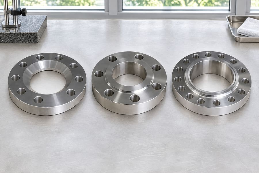
Flange facing defines the contact geometry between mating flanges and a gasket. RF uses a projecting land; FF presents a flat face; RTJ locates a metal ring in a groove. Each requires different gasket and machining details.
This guide compares their sealing interfaces, compatibility, inspection points, and specification requirements for industrial piping projects and procurement decisions.
Raised Face (RF) Flanges: Geometry, Gaskets, and Applications
RF Flange Geometry and Sealing Mechanism
A raised face flange features a machined annular surface that projects above the surrounding flange face. This raised section provides the designated contact area for the gasket and concentrates the joint’s compressive loading within that region.
Closing an RF joint compresses its gasket against the two projecting annular lands. Tightening the connecting bolts brings the surfaces together and compresses the gasket according to its material properties and the specified assembly procedure.
Unlike a flat face design, the RF configuration does not normally use the entire flange face as its gasket contact area. The raised portion defines the sealing interface, making its diameter, height, and surface condition important dimensional characteristics.
Find the land diameter and height in the dimensional table for the specified flange size and rating. Engineers should therefore identify the exact standard and edition rather than applying dimensions from another flange series or assuming all RF surfaces share identical geometry.
Common Gasket Types and RF Compatibility
Spiral-wound gaskets are commonly specified for RF flange joints where their construction and material combination suit the service conditions. Their metallic winding and filler material work together to provide the required compression and recovery characteristics.
Sheet gaskets may also be suitable when the joint specification permits their use. Choose the gasket material for the fluid and the design conditions; the letters RF do not establish resistance to a particular chemical or temperature.
Gasket dimensions must correspond to the raised-face geometry. The inner diameter should avoid obstructing the flow passage, while the outer diameter must provide the intended sealing coverage without creating interference with surrounding flange features.
Thickness also influences the assembled joint. A gasket that is too thick, too thin, or incorrectly sized can change compression behavior and affect the relationship between bolt loading and gasket contact pressure.
Engineers should check the mating flange configuration before specifying an RF gasket. Two nominally compatible flanges may still require different gasket arrangements because their facing dimensions, bore geometry, or applicable standards differ.
Operating conditions also influence gasket selection. For procurement purposes, design pressure and design temperature should be used as the governing design basis, including relevant anticipated excursions, rather than relying only on ordinary steady-state operating readings.
Flat Face (FF) Flanges: Geometry and Full-Face Gasket Compatibility
FF Flange Geometry and Sealing Mechanism
A flat face flange has a continuous planar sealing surface without the raised annular section found on an RF flange. Its gasket contact area can extend across the flange face, depending on the specified gasket arrangement.
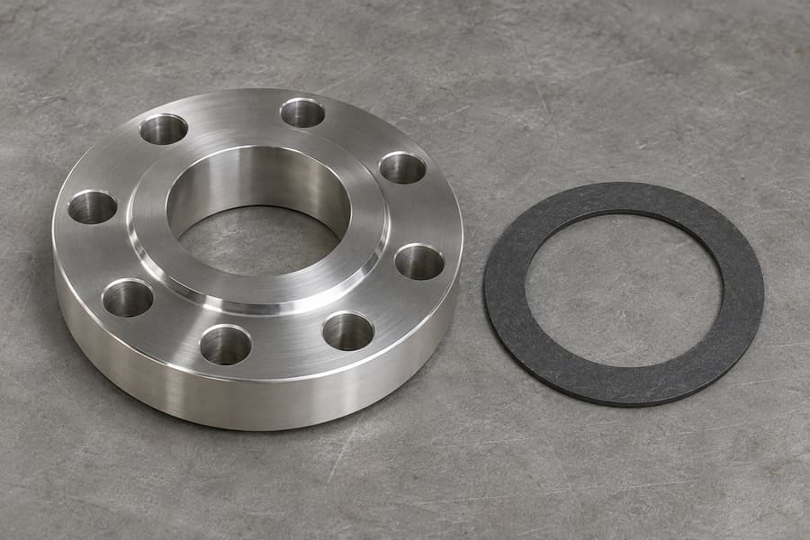
In a typical FF joint, a full-face gasket covers the sealing surface and includes openings corresponding to the flange bolt pattern. This arrangement distributes gasket contact across a broader area than the raised-face configuration.
Flat face geometry requires attention to surface flatness and alignment. If mating faces are not sufficiently parallel, bolt loading may produce uneven gasket compression, increasing the possibility of localized contact problems.
FF flanges are not automatically limited to low-pressure service. Their suitability depends on the applicable flange standard, material, dimensions, pressure-temperature rating, mating components, and engineered joint design.
Flange stiffness is particularly relevant when evaluating a flat-face connection. The broader contact arrangement does not eliminate the need to assess flange deformation under bolt loading and operating conditions.
Full-Face Gaskets and Mating Flange Considerations
Full-face gaskets are commonly associated with FF flanges because they cover the sealing surface and provide openings for the connecting bolts. Their coverage must correspond to the actual flange dimensions and bolt-hole arrangement.
Gasket material should be selected according to the process fluid, chemical exposure, design temperature, and design pressure. Thickness, compressibility, and recovery characteristics also influence how the assembled joint behaves under operating conditions.
Gasket coverage matters because the intended contact region must remain properly supported. An incorrectly sized gasket can extend beyond the intended sealing area, interfere with assembly, or leave part of the required contact surface uncovered.
Mating-face compatibility requires particular attention when an FF flange is connected to another facing configuration. An FF-to-RF combination should not be treated as equivalent to an FF-to-FF joint simply because the nominal flange sizes match.
The project specification should identify the permitted mating-face combination and corresponding gasket arrangement. Where a mixed-facing connection is proposed, engineers should verify its acceptability against the governing standard and the complete joint design.
For procurement teams, the flange drawing should identify the facing type explicitly. Describing a flange only as flat-faced may leave important questions about gasket coverage, surface finish, and mating-component compatibility unresolved.
Ring-Type Joint (RTJ) Flanges: Groove Geometry and Metal Ring Gaskets
RTJ Groove Structure and Sealing Mechanism
An RTJ flange uses a machined annular groove in its sealing face instead of a raised or continuously flat gasket-contact surface. A metallic ring gasket sits inside this groove and forms the sealing interface between the mating flanges.
When the joint is assembled, bolt loading brings the flanges together and compresses the metallic ring against the corresponding groove surfaces. The resulting contact creates localized sealing pressure at the ring-to-groove interface.
Unlike conventional sheet or spiral-wound gaskets, an RTJ ring gasket depends heavily on the accuracy of its cross-sectional profile and the matching groove geometry. Small dimensional discrepancies can affect seating and contact distribution.
Machine the ring seat from the controlling groove detail, including its prescribed profile and dimensional limits. Width, depth, profile shape, diameter, and concentricity all influence whether the specified ring can seat correctly.
Surface condition is equally important. Scratches, dents, corrosion, or machining defects along the groove contact surfaces can interfere with the intended metal-to-metal interface, even when the principal groove dimensions appear correct.
R, RX, and BX Ring Gasket Profiles
Ring-joint gaskets are available in different profile families, and their designations must be interpreted within the applicable equipment and flange standards. The R profile is commonly addressed in ASME ring-joint flange applications.
R-profile rings have a defined cross-sectional geometry intended to fit the corresponding RTJ groove. The exact ring designation and dimensions must match the flange specification rather than being selected solely by nominal pipe size.
RX and BX profiles have different geometries and are associated with relevant API equipment systems. They should not be presented as generic alternatives to R-profile rings or assumed to be drop-in substitutes for ordinary ASME flange grooves.
Before ordering a replacement ring, compare its designation with the exact groove specified for the installed connection. Engineers must confirm the applicable equipment standard, groove configuration, and specified ring profile together.
Ring material selection also requires consideration of the process environment. Chemical compatibility, temperature exposure, corrosion resistance, and mechanical properties all influence the suitability of the selected metallic gasket.
Hardness requirements should be considered in relation to the flange groove material and the applicable ring-joint specification. The intended contact behavior depends on the specified material combination, not simply on choosing the hardest available ring.
Ring dimensional accuracy is important for both initial installation and subsequent maintenance. Reusing a ring without checking its condition may introduce problems if it has been deformed, scratched, corroded, or otherwise damaged during previous assembly.
RF vs FF vs RTJ: Key Differences and Selection Factors
Comparison of the Three Flange Facing Types
Although all three facing types provide a gasket interface, their geometries create different assembly arrangements. Understanding these differences helps engineers identify the correct gasket, define machining requirements, and avoid mismatched components during procurement.
| Comparison Factor | RF | FF | RTJ |
| Face geometry | Raised annular surface | Flat planar surface | Machined annular groove |
| Typical gasket | Spiral-wound or specified sheet gasket | Full-face or specified flat gasket | Metallic ring gasket |
| Contact arrangement | Gasket against raised face | Gasket against flat face | Ring against groove |
| Main machining focus | Raised-face diameter, height, and finish | Face flatness and surface finish | Groove profile and dimensions |
| Critical compatibility | Gasket dimensions and mating face | Gasket coverage and mating face | Ring profile and groove geometry |
| Inspection priorities | Face dimensions and surface condition | Flatness, parallelism, and surface condition | Groove dimensions and contact condition |
How to Select the Appropriate Facing
Facing selection should begin with the piping design specification rather than an assumption that one configuration is inherently better. The specified connection must satisfy the applicable design requirements and remain compatible with its mating components.
For an RF connection, engineers should evaluate the raised-face dimensions, gasket construction, and contact arrangement. For replacement work, obtain the old joint’s facing reference before reusing its gasket dimensions.
For an FF connection, the main considerations include full-face gasket coverage, flange stiffness, and the compatibility of both mating surfaces. An apparently flat face can still be paired with an unsuitable gasket or a mating component that loads it incorrectly.
For an RTJ connection, the ring profile and groove must be treated as a matched specification. Procurement documents should identify the applicable ring designation, material, and relevant dimensional requirements rather than simply requesting an RTJ flange.
Engineers should also consider the process medium, design pressure, design temperature, maintenance conditions, and gasket replacement requirements. These factors help determine whether the proposed facing and gasket arrangement are appropriate for the complete piping joint.
Flange Standards, Pressure Ratings, and Assembly Requirements
Material Specifications vs. Dimensional Standards
Flange procurement involves several different technical documents, and each controls a different part of the product or joint. Confusing these documents can result in an order that identifies the material correctly but leaves critical dimensional or assembly requirements incomplete.
ASTM material specifications define requirements associated with material grades, including relevant chemical composition, mechanical properties, and product requirements. A material document cannot serve as the drawing or as the complete rating basis for the finished connection.
ASME flange standards address dimensional and rating requirements for the flange configurations within their respective scopes. ASME B16.5 and ASME B16.47 are examples used for different flange size ranges and applications.
EN 1092-1 provides a European flange standard covering specified dimensions, pressure designations, materials, and facing arrangements within its scope. Its requirements should not be assumed to be interchangeable with an ASME flange merely because nominal sizes appear similar.
The distinction between material and dimensional standards is important when preparing purchase orders. A material grade identifies what the flange is made from, while the dimensional standard establishes the applicable geometry and related requirements.
| Specification Category | Primary Purpose | Information to Verify |
| Material specification | Defines material requirements | Grade, composition, mechanical properties, and product requirements |
| Dimensional standard | Defines flange geometry and applicable dimensions | Nominal size, facing, bolt pattern, dimensions, and standard edition |
| Pressure-temperature rating | Establishes permitted rating conditions under the governing standard | Material group, size, rating designation, and temperature |
| Assembly requirements | Controls how the complete joint is assembled | Gasket, bolting, alignment, tightening procedure, and installation requirements |
For example, specifying a material grade without identifying the governing flange dimensional standard does not fully define the required product. The supplier still needs the applicable flange series, nominal size, facing, and pressure designation.
Likewise, selecting an ASME dimensional standard does not automatically resolve every material requirement. The purchase specification must identify the applicable material specification and grade separately.
How Pressure-Temperature Ratings Are Determined
A flange pressure-temperature rating is determined by the governing standard and its applicable material and dimensional provisions. Relevant factors include material group, nominal size, rating designation, and the temperature at which the flange operates.
ASME pressure classes and EN PN designations are different rating systems. They should not be treated as direct numerical equivalents without checking the relevant standard and the engineering requirements of the proposed connection.
Design pressure and design temperature provide the basis for evaluating the piping component against the applicable rating. These values may differ from ordinary operating readings because the design basis can account for foreseeable operating excursions and specified design conditions.
Engineers should therefore check the actual design pressure-temperature combination rather than comparing a flange designation with normal operating pressure alone. The applicable material group and size must also be considered when determining whether the rating is acceptable.
Facing type does not independently establish the pressure rating. An RTJ designation does not automatically make a flange suitable for every high-pressure application, just as an RF or FF designation does not independently establish a particular pressure capability.
The complete specification must also consider the governing piping code, project requirements, and the compatibility of the mating flange and gasket. A correct facing cannot compensate for an incorrectly selected material or rating.
Gasket, Bolting, and Assembly Requirements
Gasket selection is part of the complete flange joint design. Engineers must consider material compatibility, gasket dimensions, design conditions, and the compression characteristics required by the specified facing configuration.
Bolting requirements should identify the appropriate bolt and nut materials, dimensions, and relevant mechanical properties. The selected fasteners must be compatible with the joint specification and the intended installation conditions.
Flange alignment is another important assembly consideration. Excessive misalignment can introduce uneven loading, make gasket positioning difficult, and create additional stresses that are not addressed simply by increasing bolt tightening effort.
Check gasket alignment in an RF or FF assembly before applying the first bolt load. For RTJ joints, the ring must be properly seated in the corresponding groove, with its profile and condition verified against the specified requirements.
Controlled tightening procedures should define the required sequence and bolt-loading approach. Torque values depend on factors such as fastener dimensions, material, lubrication, thread condition, and the specified target bolt load.
Consequently, no single torque value can be applied universally to every flange facing or gasket arrangement. The installation procedure should follow the engineered requirements for the actual bolting and gasket combination.
Machining and Inspection Requirements for RF, FF, and RTJ Flanges
Sealing Surface Finish and Condition
Sealing-face machining affects how a gasket contacts the flange surface. Surface texture influences local contact conditions, while overall face geometry determines whether the intended gasket area can be compressed evenly during assembly.
Surface roughness and flatness describe different characteristics. Roughness relates to the small-scale texture left by machining, whereas flatness concerns the overall form of the sealing surface.
A flange can have an acceptable surface texture but still contain a geometric deviation that affects gasket contact. Conversely, a geometrically flat face may have scratches or tool marks that interfere with the intended sealing interface.
RF machining may include specified serrated finishes or other surface textures depending on the applicable standard and gasket requirements. The raised-face height, diameter, and condition must also remain within the specified dimensional limits.
FF machining focuses on producing the required planar contact surface. Face flatness and parallelism are particularly relevant because uneven contact can influence gasket compression across the flange.
RTJ machining requires greater attention to the groove profile and its contact surfaces. Tool marks, localized damage, or incorrect groove geometry may affect the seating relationship between the metallic ring and flange.
There is no single surface roughness requirement suitable for every facing and gasket combination. The specified value and measurement method should come from the exact applicable standard, project drawing, and gasket requirements.
Machining inspections should also identify visible damage such as corrosion, dents, burrs, and scratches. These conditions deserve attention because defects located within the actual gasket contact region may be more significant than similar marks elsewhere.
Critical Dimensional Inspection Points
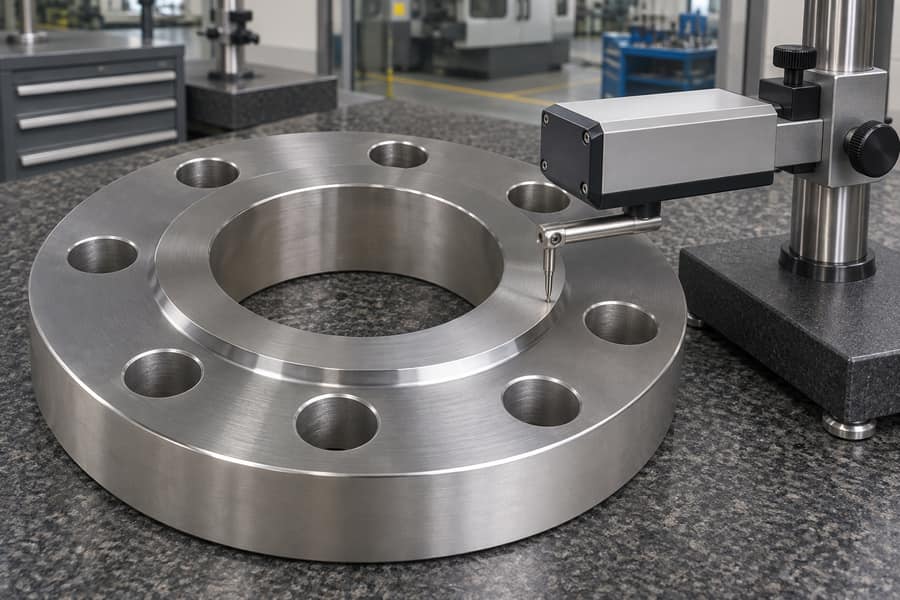
Dimensional inspection should follow the flange drawing and the applicable standard. The inspection plan needs to distinguish between general flange dimensions and the specific features that directly establish the sealing interface.
For RF flanges, inspection should cover raised-face height and diameter, surface condition, and the required face geometry. The raised portion should also be checked for damage that could interfere with gasket positioning or contact.
For FF flanges, inspectors should examine face flatness, parallelism, and the condition of the planar sealing surface. Compare the drilled pattern and the central opening with the released drawing, including their location relative to the specified datums.
RTJ inspection requires attention to groove width, depth, profile, diameter, and concentricity. The groove should be checked against the specified ring designation because dimensional compatibility depends on the relationship between both components.
Inspection should distinguish between a dimensional deviation and a surface defect. A groove may have the correct nominal dimensions while containing localized damage, so checking only width and depth would provide an incomplete assessment.
A measurement is useful only if the instrument can resolve the drawing tolerance and reach the feature without compromising the setup. Critical dimensions should be recorded using the specified reference datums and measurement conditions.
Inspection records should identify the drawing revision, applicable standard, measured dimensions, and acceptance criteria. This makes it easier for engineering and procurement teams to review whether the supplied flange corresponds to the approved specification.
Handling and storage also affect sealing-face condition. Raised faces should be protected from impact, while RTJ grooves require particular care because damage to the narrow contact surfaces may affect subsequent gasket seating.
Custom Forged Flange Manufacturing at Boberry Machining
Material and Flange Configuration Options
Material selection for forged flanges depends on the piping specification and intended service conditions. Boberry Machining’s stated product scope includes carbon steel, stainless steel, alloy steel, and duplex steel flange options.
Different connection configurations address different piping arrangements. The available scope includes weld-neck, slip-on, blind, and other flange styles, with the required facing identified according to the project specification.
RF, FF, and RTJ requirements should be considered together with the selected material and flange configuration. Not every material, size, connection style, and dimensional standard should be assumed to be available in every possible combination.
Procurement teams should therefore confirm the specific combination before placing an order. The material grade, nominal size, pressure designation, facing, and applicable standard should all be stated in the technical inquiry.
Custom Machining and Technical Drawing Requirements
Some piping projects require dimensions or machining features beyond a standard flange configuration. Custom bore dimensions, bolt-hole layouts, and sealing-face requirements should be identified through approved technical drawings.
For RF and FF designs, drawings should clearly define the required sealing-face geometry and relevant surface finish. This helps distinguish the gasket contact area from other flange surfaces that do not perform the same function.
For RTJ designs, the drawing should identify the applicable groove profile and its corresponding ring designation. Providing only a general RTJ description may leave uncertainty about the required groove dimensions and gasket compatibility.
Custom machining requirements should specify the relevant dimensions, tolerances, datums, and inspection expectations. Where a standard dimension is modified, the drawing should identify the deviation clearly rather than relying on an informal description.
Drawing revisions must also be controlled throughout procurement and manufacturing. Changes to bore dimensions, bolt-hole positions, facing geometry, or groove details can affect component compatibility and should be confirmed before production proceeds.