
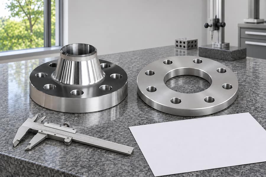
Forged flange dimensions govern how piping components align, bolt together, and seat gaskets. A measurement becomes meaningful only when its drawing reference, rating, connection style and sealing detail are known.
Understanding these relationships helps prevent drawing errors, mismatched connections, and avoidable machining changes. This guide covers dimensional references, tolerances, inspection, and purchase information for flanges supplied by Boberry Machining.
Understanding Forged Flange Size Designations and Standards
Nominal Size vs. Actual Flange Dimensions
Nominal pipe size (NPS) and nominal diameter (DN) identify a pipe or connection size category; neither directly states a flange’s outside diameter. Treat the designation as a starting reference, not a measured dimension.
Flange outside diameter is controlled by the applicable dimensional standard, class, type, and sometimes series. Bore is separate and selected for the pipe connection. Two parts carrying the same size designation may still differ in overall diameter, metal thickness, opening dimensions and drilling layout.
Pipe schedule identifies a wall-thickness series, not a flange pressure class. For one nominal size, a different schedule changes the pipe’s inside diameter. A weld-neck bore may align with the pipe passage, while a slip-on bore must fit over the pipe outside diameter.
How Standards, Pressure Classes, and Flange Types Affect Dimensions
Identify the dimensional standard before selecting measurements. ASME, DIN, and EN documents define flange dimensions within their respective scopes. State the exact document and, where required, edition; a standards organization name alone is not a complete specification.
ASME develops standards such as ASME B16.5. ANSI does not independently write that document’s technical flange dimensions; its role is associated with approval and accreditation within the standards system. “ANSI flange” alone may leave the dimensional reference unclear.
CEN develops EN standards, while DIN EN identifies the German national adoption of an EN document. DIN EN is not a separate, universally interchangeable geometry. Identify the exact EN document and applicable adoption rather than assuming similar designations share every dimension.
The finished geometry changes with the rating category, connection design and chosen dimensional series. A class designation is not a standalone pressure value independent of temperature and material.
Where a standard provides different series, identify it because OD, bolt arrangement, or other dimensions may differ. For ASME B16.47 flanges, Series A and Series B should not be assumed interchangeable.
Material Specifications vs. Dimensional Standards
A material specification defines grade and material requirements; a dimensional standard defines flange geometry. ASTM material specifications may cover carbon, stainless, alloy, or other steels, but the grade does not establish flange dimensions.
Pressure-temperature ratings depend on the governing standard, material group, class, and temperature. They are not determined by thickness alone. Distinguish design pressure and design temperature from ordinary operating readings: design conditions establish the design basis even when normal operation is lower.
Key Forged Flange Dimensions and Their Functions
Flange Outside Diameter and Thickness
Outside diameter (OD) is the flange body’s overall external diameter. It affects space and mating clearance, and must be checked against the selected standard, class, type, and series rather than inferred from NPS.
Body thickness is measured at the location defined by the standard or drawing. It is not raised-face projection, hub height, or another projecting feature. Thickness contributes to joint stack-up and bolt-length selection, but is not a standalone measure of pressure capacity.
Bore Diameter and Pipe Schedule
The bore is the internal opening through a flange. Its required diameter depends on connection style, pipe outside diameter, wall thickness, and specified internal alignment. The size label is insufficient to establish the actual opening diameter.
For a weld-neck flange, coordinate bore and weld-end preparation with pipe schedule and butt-weld connection; a mismatch can create an internal step. A slip-on bore must accommodate pipe outside diameter and intended fit, not simply copy a weld-neck bore of the same nominal size.

Bolt Circle Diameter and Bolt-Hole Dimensions
Bolt circle diameter (BCD), also called pitch circle diameter (PCD), is the diameter of the circle passing through bolt-hole centers. It locates the pattern relative to the flange center and is a primary mating check.
Define the pattern by hole quantity, hole diameter, BCD, spacing, and angular orientation. Hole count alone is insufficient. Hole diameter establishes fastener clearance; BCD and orientation establish alignment. For custom layouts, show the datum and reference axis clearly.
Hub Dimensions and Weld-End Geometry
A weld-neck flange has a hub transitioning from the body toward the pipe weld end. Relevant dimensions include hub diameter, length, taper, bore, and end preparation, which together define the butt-weld connection geometry.
Weld-end diameter, bevel, land, and wall transition should follow the applicable standard, welding specification, or approved drawing. Hub geometry also affects welding access. Specify non-standard pipe walls or end preparations directly rather than relying on nominal size.
| Dimension | Definition | Engineering purpose |
| Outside diameter | Overall external flange diameter | Mating clearance and dimensional identification |
| Body thickness | Thickness at the defined measurement location | Joint stack-up and dimensional compatibility |
| Bore diameter | Internal opening through the flange | Pipe fit and internal passage alignment |
| BCD / PCD | Circle through bolt-hole centers | Bolt-pattern alignment |
| Bolt-hole diameter | Diameter of each fastener hole | Specified bolt clearance |
| Hub dimensions | Hub diameter, length, and profile | Connection geometry and weld access |
| Weld-end dimensions | End diameter and preparation profile | Pipe fit-up and welding compatibility |
This table identifies common inspection features, not a universal dimension schedule. Actual values and tolerances must come from the applicable standard, class, type, series, and approved drawing.
How Different Flange Types Affect Dimensions
Weld Neck Flange Dimensions
Review body OD and thickness, bore, hub profile, weld-end geometry, bolt pattern, and facing. Each feature has its own measurement reference. Pipe schedule matters because bore and weld end must suit the specified pipe wall and joint preparation.
A flange selected by nominal size alone may still have an unsuitable bore or end dimension. If internal alignment matters, state the required relationship between flange bore and pipe passage on the drawing.
Slip-On Flange Dimensions
A slip-on flange bore allows the pipe to pass through before the specified welds are made. It is therefore related to pipe outside diameter and assembly clearance, not simply the pipe’s internal diameter.
Check OD, body thickness, bore, facing, and bolt pattern, then confirm the pipe can be inserted and welded as intended. Identify special bore or fit requirements; do not transfer weld-neck hub dimensions to a slip-on design.
Blind Flange Dimensions
A blind flange closes a piping opening and has no through-bore. Its principal checks are OD, body thickness, bolt-circle diameter, hole quantity and diameter, and facing. The mating flange standard and class establish the interface geometry.
Design suitability depends on the applicable pressure-temperature rating and design conditions, not thickness or nominal size alone. Confirm material specification, class, design temperature, and governing code requirements.
Other Forged Flange Connection Styles
Socket-weld, threaded, and lap-joint configurations introduce different pipe-interface geometry. Socket dimensions, thread details, or the relationship between a stub end and backing flange must follow the selected design and applicable reference.
Forged Flange Facing Dimensions: RF, FF, and RTJ
Raised Face (RF) Dimensions
A raised face provides a defined gasket seating area above the surrounding flange surface.
Its geometry includes raised-face diameter and height or projection, as defined by the standard; these are distinct from overall flange thickness. Check both the opposing component and the gasket footprint before approving this interface.
Checking the FF Contact Plane
On an FF component, the gasket contact region is not elevated above the surrounding face. Requirements include facing diameter, flatness, and specified surface finish. Flatness describes geometric variation, while finish describes surface texture; meeting one does not automatically demonstrate compliance with the other.
Verifying the RTJ Ring Seat
The RTJ interface locates a solid metal sealing ring within a precisely cut circular channel. The applicable standard and ring configuration define groove profile, width, depth, and position. Specify the ring designation and compatible groove reference; “RTJ” alone does not identify every machining detail.
Sealing-Face Machining Requirements
State facing type, controlled dimensions, finish requirement, and applicable flatness or geometric tolerance separately. Use datums that relate the flange center, bolt pattern, and sealing face, especially for custom diameters or groove positions. Resolve conflicts between standard and project-specific features before machining.
Forged Flange Dimensional Tolerances and Custom Machining
Standard Dimensional Tolerances
A nominal dimension states intended size; a tolerance defines permitted variation. The governing standard may specify limits for OD, thickness, bore, bolt holes, and facing geometry. Use the provisions that apply to the exact component covered by the cited document.
Do not apply one tolerance to every feature or transfer a value from another standard. Some dimensions are controlled by the standard, while others are drawing-specific. Resolve conflicts before production.
Geometric controls can be as important as size limits. Bolt-hole position, face flatness, concentricity, and bore alignment may affect assembly even when individual diameters are within tolerance. Identify datums and geometric tolerances where the relationship is functionally important.
Consider accumulated variation across the joint. A flange may meet its individual limits yet create a fit-up problem with the pipe, gasket, bolts, and mating flange. Review functional interfaces as an assembly.
Custom Bore and Bolt-Hole Machining
Custom bore machining may be needed for a specified pipe wall, internal transition, or equipment connection. State target diameter, measurement location, tolerance, and any transition or concentricity requirement affecting the passage.
For a custom bolt pattern, define BCD, hole diameter, quantity, angular spacing, orientation, and locating datum. If the pattern is rotated relative to a reference axis, show the angle and reference clearly.
Where possible, provide the mating interface drawing or verified dimensions. This helps distinguish a deliberate custom pattern from a mistaken reading of a standard. Boberry Machining’s scope includes custom bore and bolt-hole machining to agreed drawings.
Custom Facing and Dimensional Adjustments
Custom facing may involve an RF or FF diameter, specified finish, or RTJ groove configuration. Dimension each controlled feature and tolerance clearly; a general note should not replace measurements that determine gasket seating.
Relate the facing to the flange centerline and bolt pattern through clear datums. Boberry Machining’s scope includes carbon, stainless, alloy, and duplex steel flanges, with machining requirements defined by agreed drawings. Confirm the actual material, size, type, and standard combination for each order.
How to Inspect and Verify Forged Flange Dimensions
Essential Dimensional Inspection Points
Inspect against the approved drawing and applicable standard, using defined measurement locations. Check OD and body thickness, then the bore, bolt pattern, hub, weld end, and facing features relevant to the flange type.
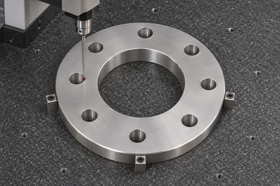
For bolt patterns, verify hole count, diameter, BCD, and position relative to the datum. Adjacent-hole spacing alone may not establish the complete pattern. A coordinate method or suitable fixture can verify center locations and orientation.
Weld-neck inspections include hub profile and weld-end dimensions; slip-on inspections focus on bore and insertion fit; blind-flange inspections focus on thickness, bolt pattern, and facing. Check RF or FF geometry and finish as specified, and verify RTJ groove profile with a suitable method.
Dimensional Measuring Methods and Equipment
Calipers and micrometers suit many accessible external dimensions when their range and resolution match the feature and tolerance. Bore gauges or other suitable internal instruments measure internal diameters. Choose equipment according to geometry and required accuracy.
Large bolt patterns may require a coordinate measuring machine, inspection fixture, or another controlled method. Establish the flange center and datum surfaces before evaluating hole locations; a measurement without a defined reference may not represent the drawing requirement.
Use an appropriate surface measurement method when a numerical finish is specified. Flatness and groove geometry also require methods suited to their tolerances and profiles. Measuring equipment should be calibrated and used consistently.
Inspection Reports and Dimensional Documentation
A useful report identifies drawing revision, standard reference, feature, nominal value, tolerance, measured result, and acceptance status. Include the method where it helps explain verification of a critical or unusual feature.
Keep dimensional reports distinct from material certificates. Material documents establish grade and traceability; dimensional records show whether measured geometry meets requirements. Request additional records when the purchase specification or governing code requires them.
| Inspection item | Verification focus | Primary reference |
| Overall dimensions | Outside diameter and body thickness | Applicable standard and drawing |
| Bore | Internal diameter and specified transition | Drawing and pipe connection requirements |
| Bolt arrangement | BCD, hole diameter, count, and position | Mating flange specification and datum scheme |
| Hub and weld end | Diameter, length, taper, and end preparation | Approved drawing and connection requirements |
| Sealing face | Facing geometry, flatness, and surface finish | Facing specification |
| RTJ groove | Groove profile and controlling dimensions | Applicable RTJ standard and ring designation |
| Material identity | Grade and traceability | Material specification and certificate |
Flange Dimensional Compatibility and Purchase Specifications
Matching Flange Dimensions for Piping Connections
Flanges with the same nominal size are not necessarily compatible. Check dimensional standard, class, type, series where applicable, facing, bolt pattern, and bore or connection geometry. The complete interface must suit the piping arrangement.
Compare the standard and class first, then the physical features at the joint. Verify BCD and hole arrangement, facing and gasket seating dimensions, and OD or thickness where they affect clearance or stack-up. For weld-neck connections, include pipe schedule and weld-end details.
When components use different standards, similar size or class labels do not establish interchangeability. Compare controlled dimensions and rating basis. Document any accepted deviation through the responsible engineering authority before procurement or installation.
Gasket, Bolting, and Assembly Requirements
Gasket selection depends on facing configuration, dimensions, service conditions, and the piping specification. The gasket must suit the seating area and mating surfaces. Do not assume a gasket arrangement transfers between RF, FF, and RTJ joints.
Bolting requirements include diameter, quantity, length, material, and assembly procedure. Length depends on flange thickness, gasket, specified washers, and nut engagement. Hole clearance is dimensional; tightening sequence and target load belong to the approved assembly procedure.
Check pressure-temperature rating alongside dimensions, not as a substitute for them. The rating must suit design pressure and design temperature under the governing standard and material group. Ordinary operating readings do not independently redefine design conditions.
What to Include in a Forged Flange Drawing or Purchase Order
A purchase description should identify the flange configuration and control features that determine fit. State the drawing number and revision, and identify notes that supplement or modify the referenced standard.
- Standard: Governing dimensional standard and edition.
- Nominal size: NPS or DN and the pipe connection.
- Pressure class: Required class or rating designation.
- Type and series: Weld-neck, slip-on, blind, or other configuration, plus series where relevant.
- Material: Material specification and grade.
- Facing: RF, FF, or RTJ, including non-standard details.
- Bore: Required diameter, pipe schedule, and internal transition.
- Bolt pattern: BCD, hole quantity, diameter, spacing, and orientation.
- Hub and weld end: Required profile, end dimensions, and preparation.
- Tolerances: Standard tolerances and additional drawing-controlled limits.
- Inspection: Dimensional reports, material documentation, and contractually required records.
For custom forged flange work, attach a dimensioned drawing with datums, critical interfaces, tolerances, and required inspection records. Boberry Machining can review specified material and machining requirements against the agreed drawing so bore, bolt-hole, facing, and connection details are defined before the order is finalized.