
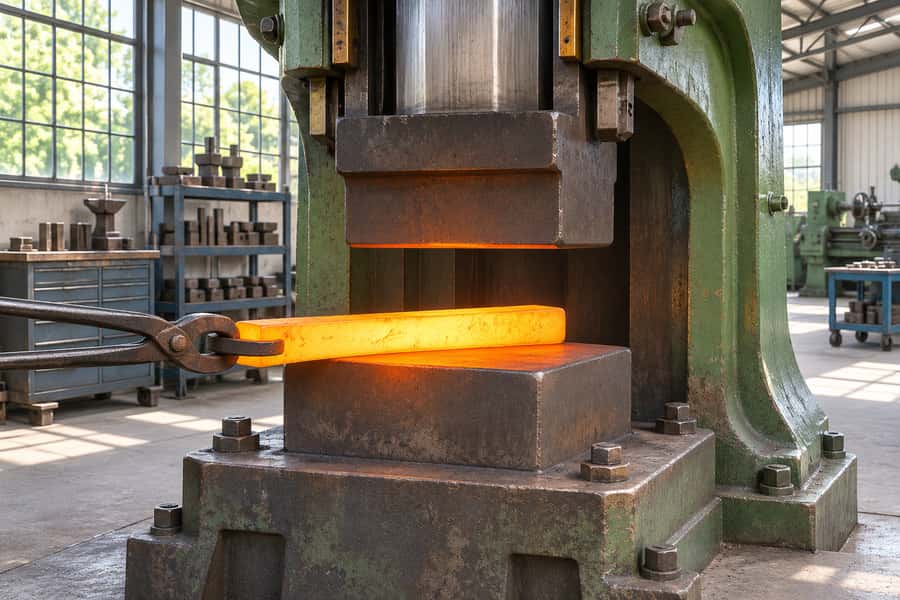
A drop hammer belongs to the wider family of impact-forging machines. A descending ram delivers impact energy to deform metal, while hammer forging also includes other hammer configurations.
The important distinctions involve how impact energy is delivered, which dies shape the workpiece, and how the component is processed. Neither label guarantees strength, accuracy, or cost.
What Is the Difference Between Drop Forging and Hammer Forging?
The main difference is terminology and equipment scope. Drop forging describes a particular hammer operation, whereas hammer forging encompasses a broader range of machines that deform metal through repeated impacts.
Both methods rely on plastic deformation, where sufficient applied stress permanently changes the workpiece shape without intentionally removing material. Their practical capabilities depend on equipment, tooling, and processing conditions.
What Is Drop Forging?
Drop forging uses a descending hammer ram to deliver impact energy to a workpiece positioned between dies. The ram may fall under gravity or receive additional acceleration from a powered mechanism.
The process is commonly associated with impression-die production, where shaped cavities guide the workpiece toward its required geometry. However, drop hammers can also operate with open dies.
Industrial drop forging services may involve several forming stages, depending on component complexity. Billet preparation, heating, forming, flash trimming, and finishing must be matched to the specified component.
An important distinction is that the word drop describes how the hammer approaches the workpiece. It does not independently identify the tooling configuration or finished component quality.
What Is Hammer Forging?
Hammer forging is a broader manufacturing category in which repeated impacts plastically deform metal. Equipment may include gravity-drop hammers, power-assisted hammers, and other industrial hammer arrangements.
Unlike manual blacksmithing, industrial hammer forging typically uses mechanized equipment capable of delivering controlled forming blows. Operators manage workpiece positioning, process settings, and the required deformation sequence.
Hammer forging may use open dies for progressive shaping or impression dies for more defined geometry. The die configuration remains an independent decision from the hammer mechanism.
Therefore, two components described as hammer forged may have undergone substantially different manufacturing routes. Their geometry, production quantity, and dimensional requirements help explain those differences.
How Does Hammer Energy Differ Between Equipment Types?
Industrial forging hammers deliver energy through different mechanical arrangements. Three relevant configurations illustrate why the general term hammer forging covers more than one machine type.
- Gravity-drop hammers: A raised ram falls under gravity, converting gravitational potential energy into impact energy. Ram mass and drop height influence the available energy.
- Power-assisted drop hammers: An additional power source accelerates the descending ram. Operating conditions and equipment design influence the energy delivered during each stroke.
- Counterblow hammers: Opposing moving masses strike toward one another, delivering forming energy through their relative motion rather than relying on a single descending ram.
Different hammer designs influence impact delivery, vibration transmission, and workpiece handling. These equipment differences do not automatically establish superior material properties or dimensional accuracy.
The correct comparison therefore begins with the actual hammer configuration, die arrangement, and manufacturing requirements rather than treating drop forging and hammer forging as mutually exclusive processes.
Drop Forging vs. Hammer Forging: Key Differences at a Glance
Although the terminology overlaps, understanding its practical meaning helps engineers interpret manufacturing proposals. The following comparison separates equipment descriptions from the factors that actually determine component performance.
| Comparison Factor | Drop Forging | Hammer Forging |
| Definition | Forging with a descending hammer ram | General category of impact-based hammer forging |
| Equipment | Gravity-drop or power-assisted drop hammers | Drop hammers and other industrial forging hammers |
| Force application | Repeated impact energy | Repeated impact energy |
| Die configuration | Often impression dies, but open dies are possible | Open dies or impression dies |
| Dimensional accuracy | Depends on tooling, equipment, and finishing | Depends on tooling, equipment, and finishing |
| Mechanical properties | Depend on alloy, deformation, and heat treatment | Depend on alloy, deformation, and heat treatment |
| Production cost | Depends on tooling, quantity, and processing | Depends on tooling, quantity, and processing |
The table does not compare two exclusive manufacturing alternatives. Every drop-forging operation using a forging hammer belongs to the broader hammer-forging category described here.
For example, a gravity-drop hammer using impression dies may produce a relatively defined forging shape. Another hammer using open dies may progressively elongate a billet.
Their differences arise primarily from tooling, operating conditions, and production objectives. The terminology alone cannot establish which component will require less machining or achieve tighter dimensions.
Open-Die and Impression-Die Forging: How Tooling Changes the Process
Die configuration has a direct influence on metal flow, component geometry, and manufacturing flexibility. It should be evaluated separately from whether a hammer or press supplies the forming force.
Working with Open Hammer Dies
With open tooling, the billet remains free to spread beyond the contact areas as the hammer strikes. Flat or simply contoured tools allow material to spread as successive blows change its shape.
During open-die forging, the workpiece may be rotated, repositioned, or advanced between impacts. These movements support operations such as drawing, upsetting, and localized shaping.
Open-die methods can be practical for larger components, relatively simple sections, or projects requiring flexible tooling. They may also produce preforms for subsequent manufacturing stages.
However, open-die forging generally requires sufficient machining allowances where finished dimensions are critical. Achievable geometry depends on the equipment, manipulation method, and workpiece characteristics.
Impression-Die Hammer Forging
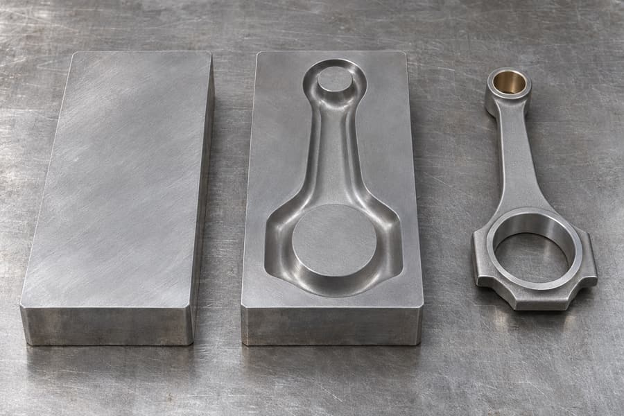
Impression-die forging uses shaped cavities to guide material into a more defined geometry. Repeated impacts help distribute metal throughout the impression as the workpiece deforms.
Complex components may require preliminary forming operations before entering a finishing impression. This sequence helps position material where additional deformation will be necessary.
As ordinary impression dies close, surplus stock can squeeze into a thin fringe around their meeting faces. A later trimming operation removes this fringe.
Because impression tooling establishes much of the component geometry, it can support repeatable production when dies and operating conditions are properly maintained.
The tradeoff is greater tooling investment and preparation. Dedicated impressions become more attractive when geometry, repeat demand, and production quantity justify their development.
Reading Closed-Die Terminology on a Process Proposal
In industrial terminology, closed-die forging frequently refers to impression-die forging. The terms often describe the same general family of shaped-die operations.
However, stricter terminology distinguishes flashless closed-die forging, where material is confined within a closed cavity without an intended flash outlet.
Flashless operation requires particularly careful control of billet volume and cavity filling. Excess stock or insufficient material can create different forming and quality problems.
Consequently, open-die, closed-die, and impression-die forging should not be treated as three universally separate categories. The actual die design provides the necessary clarification.
How Is Hammer Forging Different from Press Forging?
Hammer forging generally delivers deformation energy through relatively brief impacts. Press forging applies force through a controlled forming stroke, with the loading behavior depending on press design.
Hammer operations may require several blows to achieve the intended shape. Press operations can provide a different combination of stroke control, force application, and deformation progression.
Neither equipment type determines whether the tooling is open or impression shaped. Both categories can employ different dies according to component requirements.
Selection should account for workpiece dimensions, alloy behavior, available equipment, die filling, and required deformation. A hammer-versus-press comparison is distinct from a drop-versus-hammer terminology discussion.
Following a Billet through Hammer Production
The general manufacturing sequence is similar across many hammer-forging operations. However, billet preparation, die configuration, forming stages, and finishing requirements vary with the component.
Material Preparation and Heating
Manufacturing begins with selecting an alloy that meets the intended mechanical properties, service environment, and applicable specifications. The initial stock condition must also support the selected forging route.
Billets are cut and prepared according to the required material volume and expected deformation. Appropriate allowances account for forging geometry, potential flash, and subsequent machining.
Heating improves the formability of metals intended for hot forging. Temperature requirements depend on the alloy, initial condition, and planned forming sequence.
Insufficient temperature control can contribute to cracking, undesirable microstructures, or inconsistent deformation. Excessive heating can also damage material quality, making controlled processing important.
Hammer Forming and Die Operation
The prepared workpiece is positioned between the dies before the hammer delivers forming impacts. Each blow changes the workpiece geometry through plastic deformation.
The forming sequence differs according to the tooling:
- Open-die forming: Operators or handling equipment reposition the workpiece between blows to develop the required geometry progressively.
- Impression-die forming: Shaped cavities guide metal flow, potentially through preliminary and finishing impressions.
- Preforming sequence: Earlier impressions move stock toward the sections that must fill during the finishing blows.
Hammer energy must be appropriate for the workpiece and forming stage. Excessive or poorly controlled deformation can contribute to defects or unnecessary die loading.
As forming progresses, temperature changes and accumulated deformation affect material behavior. Complex parts may require reheating or additional operations before final forming.
Trimming, Heat Treatment, and CNC Finishing
Impression-die forgings that produce flash generally require trimming. Open-die forgings may instead proceed to other shaping operations, cleaning, heat treatment, or machining.
Heat treatment is specified according to alloy characteristics and required properties. Normalizing, annealing, quenching, tempering, or solution treatment may be appropriate in different circumstances.
These treatments are not interchangeable. For example, austenitic stainless steels cannot be hardened through conventional quench-and-temper treatment in the same manner as suitable hardenable alloy steels.
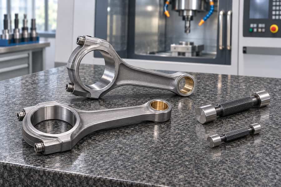
Cleaning removes scale and surface contamination where necessary. CNC machining then establishes critical dimensions, interfaces, and surface conditions that cannot be achieved economically during forging alone.
Final inspection verifies specified characteristics, completing a manufacturing route tailored to the component rather than to the label applied to the forging hammer.
What Determines Strength, Accuracy, and Quality in Hammer-Forged Components?
Hammer selection influences the forming operation, but finished component quality depends on several interacting factors. The alloy specification needs to be read alongside the forming sequence, thermal schedule, and agreed acceptance tests.
Material Flow and Mechanical Properties
Plastic deformation changes the shape and internal structure of the starting material. Depending on processing conditions, forging can modify grain structure and the orientation of material flow.
For components exposed to directional loading, favorable grain-flow orientation may contribute to mechanical performance. This benefit depends on geometry, alloy, processing, and the actual service conditions.
The thermal cycle can substantially change how a forged section resists indentation, carries load, deforms, and fractures. An inappropriate treatment can compromise the intended result regardless of the forging equipment.
Neither drop forging nor the broader hammer-forging designation guarantees superior properties. Meaningful comparisons require similar alloy conditions, processing histories, and finished acceptance requirements.
Dimensional Accuracy and Surface Finish
As-forged accuracy depends on die geometry, equipment alignment, workpiece temperature, die wear, and forming control. These factors can vary considerably between different production arrangements.
Impression dies can provide more defined geometric repeatability than general-purpose open dies for suitable parts. However, achievable tolerances still depend on the specific process and component.
Machining often establishes precision interfaces, bearing seats, mounting features, and other critical surfaces. The forging blank must contain sufficient material to accommodate those finishing operations.
Surface condition also requires attention. Scale, die contact marks, and local irregularities may need removal according to the specified inspection and finishing requirements.
Forging Defects and Quality Inspection
Forging defects can develop when metal flow, temperature, tooling, or material condition is unsuitable. Their occurrence is not determined simply by the hammer category.
Relevant issues include:
- Laps and folds: Material overlaps during deformation, potentially creating discontinuities.
- Surface cracking: Inappropriate temperature, strain, or material condition may contribute to cracking.
- Underfill: Metal fails to completely fill the intended impression.
- Die mismatch: Misalignment between die components produces an unwanted geometric offset.
- Dimensional variation: Tool wear, positioning, or process differences cause departures from specified dimensions.
Inspection may involve dimensional measurement, visual examination, and specified nondestructive testing. Where the specification calls for them, specimen tests provide evidence that the required material properties have been achieved.
Acceptance criteria should follow the drawing and applicable standards. A forging is not automatically acceptable merely because its external geometry resembles the intended finished component.
How Do Tooling, Production Volume, and Cost Influence Process Selection?
Manufacturing cost depends on the complete production route rather than the forging terminology. Tooling investment, material utilization, production quantity, secondary operations, and inspection all contribute to the final cost.
Tooling Complexity and Setup Requirements
Open-die forging often uses relatively simple tools that can accommodate different component dimensions. This flexibility may reduce dedicated tooling requirements for suitable low-volume or varied production.
Impression-die forging generally requires purpose-designed cavities. Die manufacturing, setup, maintenance, and eventual replacement must be considered when evaluating the production economics.
More complicated geometry may require multiple impressions or preliminary forming operations. These additional stages can improve material distribution but also introduce processing and tooling expenses.
Equipment setup also influences cost. Workpiece handling, die installation, temperature preparation, and process adjustments consume resources before acceptable production begins.
Production Volume and Material Utilization
Production quantity strongly influences how tooling and setup expenses are allocated. Dedicated impression dies may become more economical when their initial costs are distributed across sufficient production volume.
For smaller batches, flexible tooling can be attractive when the required geometry is achievable. However, extensive machining or additional forming operations may offset those savings.
Material utilization is another important consideration. Forging designs must account for starting billet size, deformation, potential flash, machining stock, and material removed during finishing.
For example, an impression-die process may produce a shape closer to the finished component but require dedicated tooling and flash trimming.
An alternative open-die route might use simpler dies while leaving additional material for CNC machining. Choosing a route means accounting for every operation needed to turn the starting stock into an accepted component.
Production planning must also consider rejected components, rework, and inspection. These factors affect the number of acceptable finished parts obtained from the starting material.
How to Select the Appropriate Forging Configuration
Engineers should assess equipment and tooling choices against specific component requirements. A process suitable for one geometry or production quantity may be inefficient for another.
The following table identifies practical questions that help separate equipment selection from die design and finished-part requirements.
| Engineering Requirement | Main Consideration | What to Confirm |
| Component geometry | Shape complexity and section changes | Open-die or impression-die suitability |
| Material grade | Forgeability and processing behavior | Alloy specification, heating, and heat treatment |
| Production quantity | Tooling cost and setup allocation | Batch size and expected repeat orders |
| Dimensional requirements | Forging allowances and machining | As-forged dimensions and finished tolerances |
| Mechanical performance | Material flow and final condition | Required properties and acceptance testing |
| Total manufacturing cost | Material, forming, and secondary work | Cost per accepted finished component |
This evaluation highlights why drop forging should not automatically be considered more economical than another hammer-forging arrangement. The terminology does not reveal the actual manufacturing costs.
A reliable cost comparison includes material preparation, tooling, heating, forming, trimming when applicable, heat treatment, cleaning, CNC finishing, and required inspection.
For procurement decisions, cost per accepted finished component provides a more useful basis than comparing forging operations without accounting for their different finishing and quality requirements.
Details to Settle before a Hammer-Forging Order
A successful forging inquiry begins with clear technical information. Engineers and procurement teams should describe the required component rather than specifying a hammer type without supporting manufacturing requirements.
Essential Technical Information for a Forging Inquiry
The following information helps establish whether the proposed manufacturing route can satisfy the component’s functional, dimensional, and production requirements.
- Component drawings: Provide finished dimensions, geometric features, critical tolerances, and relevant machining details.
- Material specifications: Identify the alloy grade, applicable standards, and any required starting material conditions.
- Production requirements: State the order quantity, anticipated repeat demand, and relevant delivery requirements.
- Mechanical properties: Specify required strength, hardness, toughness, or other applicable material characteristics.
- Finishing requirements: Identify heat treatment, CNC machining, surface finish, and cleaning expectations.
- Quality acceptance: Define inspection methods, testing requirements, documentation, and applicable acceptance criteria.
These details allow manufacturers to evaluate a realistic production route. Missing requirements can lead to unsuitable tooling choices, unnecessary machining, or differences in quotation scope.
Discussing the Manufacturing Route with Boberry Machining
When reviewing a proposed forging process with Boberry Machining, first clarify whether hammer or press equipment is intended. Then confirm the tooling arrangement independently.
The discussion should establish whether open dies, impression dies, or an intermediate forming sequence best suits the geometry and material requirements.
Review material preparation, heating, forming, flash trimming where necessary, optional alloy-appropriate heat treatment, cleaning, and CNC finishing as parts of the proposed manufacturing scope.
Before the route is scheduled, agree where extra stock will remain for cutting and how the finished work will be accepted. These details influence tooling design, material requirements, and the acceptance of finished components.
Ultimately, manufacturing decisions should be based on the actual equipment, die configuration, alloy, production quantity, and finished-part specifications. These factors provide a more reliable engineering and purchasing basis than treating drop forging and hammer forging as separate competing processes.