
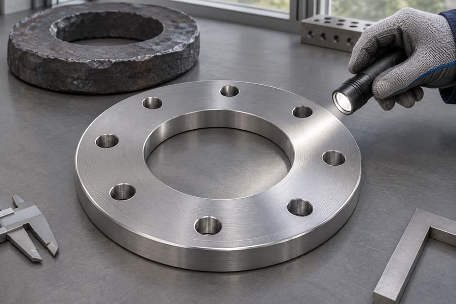
Forged flange defects can develop during billet preparation, heating, forging, heat treatment, or machining. Their appearance and location provide clues, but acceptance depends on the applicable material, product, and inspection requirements.
Understanding how each discontinuity forms helps manufacturers prevent recurrence and helps piping engineers specify appropriate examination. This article reviews common defects, controls, and acceptance considerations for forged flanges.
Common Surface Defects in Forged Flanges
Surface defects can originate from metal flow, oxidation, die conditions, and temperature variations during forging. Some remain visible after production, while others become apparent only after machining exposes previously covered material.
Identifying their formation mechanisms helps manufacturers select suitable process controls before a flange reaches final inspection. The following defects require different prevention measures rather than one general surface-finishing approach.
Laps and Folds
Laps and folds develop when metal flows over itself during forging without properly bonding at the overlapping interface. They can form when material distribution, die geometry, or the forging sequence produces an unfavorable flow pattern.
Several conditions can contribute to these discontinuities. Incorrect billet dimensions, unsuitable forging temperatures, excessive local deformation, and oxide scale trapped between metal surfaces can all affect how material fills the die cavity.
Unlike ordinary surface marks, a fold can create a discontinuity extending beneath the visible surface. Subsequent machining may expose the affected region without removing its full depth, making early process control important.
Prevention methods:
Verify billet dimensions and material distribution before forging. Maintain suitable die geometry, control forging temperature, and use an appropriate deformation sequence to encourage continuous metal flow.
Descaling is also important because oxide trapped between overlapping metal surfaces can interfere with proper consolidation. Forging tools should remain in suitable condition, with particular attention to areas where material flow changes direction.
Surface Cracks
Surface cracks can develop during forging when local stresses exceed the material’s ability to accommodate deformation. Their occurrence may relate to unsuitable forging temperatures, excessive deformation, material characteristics, or localized stress concentrations.
Cracks formed under hot-working conditions differ from those associated with deformation after cooling. Their appearance alone may not establish the formation mechanism, so manufacturing history and metallurgical evaluation can help determine the likely cause.
Crack orientation and location also matter. A discontinuity near a flange transition, hub, or other geometrical change may require particular attention because local stress conditions differ from those on a relatively flat surface.
Prevention methods:
Maintain suitable billet heating and forging conditions, avoid excessive localized deformation, and control the sequence of forming operations. Material condition and incoming quality should also be verified before production.
Intermediate surface examination can identify visible cracking before additional forging or machining operations make the discontinuity more difficult to evaluate. Any suspected crack should be assessed against the applicable inspection and acceptance requirements.
Scale Pits and Surface Inclusions
Scale pits typically result when oxide formed during high-temperature heating becomes embedded in the metal surface or is removed after leaving a localized depression. They can create an irregular surface that remains visible after descaling.
Prolonged exposure to oxidizing furnace conditions, inadequate descaling, and contaminated forging tools can increase the likelihood of scale-related surface damage. Poor surface preparation may also allow existing irregularities to remain through subsequent operations.
Non-metallic inclusions are different from oxide scale generated during heating. They originate from material production and may become exposed at the surface through forging or machining. Their evaluation depends on their nature, size, distribution, and applicable material requirements.
Prevention methods:
Control billet heating time and conditions, remove scale using suitable descaling procedures, and maintain clean forging surfaces. Incoming material requirements should address inclusion quality where relevant to the specified grade.
Inspecting the forged surface before finish machining helps identify pits and exposed inclusions while there is still an opportunity to evaluate the affected region. Additional material removal should not be assumed acceptable without checking the remaining dimensions.
Underfill and Die Mismatch
Underfill occurs when the metal does not completely occupy the intended die cavity. The resulting flange may have incomplete features, insufficient material in certain regions, or an external profile that differs from the intended forging geometry.
Insufficient billet volume, unsuitable material distribution, inadequate deformation, and improper forging temperatures can contribute to underfill. Material flow becomes particularly important around changes in section thickness and more complex flange profiles.
Die mismatch occurs when the mating die sections are incorrectly aligned during forging. It can produce an unwanted step or offset along the parting region, potentially affecting subsequent machining allowances and finished geometry.
Prevention methods:
Calculate and verify the required billet volume, maintain die alignment, and monitor die wear. Forging sequences should provide suitable material flow into the required sections without creating unnecessary localized deformation.
Dimensional checks after forging help identify underfilled regions and mismatch before finish machining. Comparing the forging with its intended geometry also helps determine whether sufficient machining allowance remains for the specified finished dimensions.
Decarburization
Decarburization occurs when carbon is lost from the surface of steel during high-temperature exposure. It is particularly relevant to carbon steel and applicable alloy steel materials exposed to oxidizing furnace atmospheres.
Excessive heating time, prolonged soaking, and inadequate atmosphere control can contribute to carbon depletion near the surface. The affected layer may have lower carbon content and different hardness characteristics from the underlying material.
The significance depends on the material grade, required surface properties, and subsequent manufacturing operations. Decarburization may be particularly relevant where surface hardness or other specified metallurgical characteristics influence the flange’s intended application.
Prevention methods:
Control furnace atmosphere, heating duration, and unnecessary high-temperature exposure. Establish suitable machining allowances where permitted by the drawing and material requirements, and verify decarburization depth when specified.
Machining can remove an affected surface layer only when sufficient material is available and the resulting dimensions remain compliant. The required removal depth should therefore be based on actual requirements rather than an assumed universal allowance.
Common Internal Discontinuities in Forged Flanges
Internal discontinuities are more difficult to identify because they may not produce visible evidence on the finished flange. Their origins can involve the original steelmaking process, billet condition, or deformation during forging.
Forging can improve material soundness by compressing and redistributing certain internal imperfections. However, deformation does not guarantee that every cavity, inclusion, or crack will disappear.
Shrinkage Cavities and Internal Porosity
Shrinkage cavities and porosity can originate during solidification and earlier billet production. Shrinkage develops when metal contraction is not adequately compensated during solidification, while porosity consists of smaller internal voids.
These discontinuities may be concentrated in particular regions of the original material. Their distribution depends on material production conditions, and subsequent forging may alter their shape, orientation, and dimensions.
Although sufficient forging deformation can close or reduce certain voids, closure should not automatically be treated as proof of sound material. Some discontinuities may remain, particularly where deformation is insufficient or unevenly distributed.
Prevention methods:
Establish incoming material quality requirements, verify heat identification and material documentation, and apply appropriate billet preparation and cropping practices. The forging process should provide suitable deformation throughout the required sections.
When internal soundness is important to the project, specify appropriate examination methods and coverage. Ultrasonic testing may be suitable, provided the examination technique is qualified for the flange geometry and material characteristics.
Non-Metallic Inclusions and Material Segregation
Non-metallic inclusions are foreign or non-metallic particles retained in steel during material production. Their composition and distribution can vary, and their presence does not automatically mean that every material batch fails its specification.
Inclusions may become elongated, redistributed, or exposed during forging. Their orientation can influence the way they appear during inspection, while their location and concentration affect their significance for the intended application.
Material segregation is different because it involves variations in chemical composition or microstructure within the steel. It can originate during solidification and may persist through subsequent processing if the material is not sufficiently homogenized.
Prevention methods:
Specify the required material grade and quality level, verify material certificates and heat identification, and establish suitable incoming inspection requirements. Material quality requirements should reflect the intended service and applicable product specification.
Where additional cleanliness or internal quality requirements are necessary, they should be defined in the purchase specification. This provides a clear basis for material acceptance instead of relying on general descriptions such as premium-quality steel.
Internal Cracks
Internal cracks can develop when unsuitable deformation conditions create excessive tensile stresses within the workpiece. Material characteristics, temperature distribution, and the geometry of the forged section can influence their formation.
Unlike visible surface cracks, internal cracks may remain concealed after forging and finish machining. Their orientation and position can also affect whether a particular ultrasonic examination technique detects them reliably.
These discontinuities should be distinguished from other internal indications, including inclusions and shrinkage-related imperfections. The inspection report should describe the observed indication according to the applicable procedure rather than automatically assigning a defect classification.
Prevention methods:
Control forging temperature, deformation sequence, and cooling conditions. Verify incoming material quality and establish appropriate inspection stages for critical regions of the forged flange.
Where ultrasonic examination is specified, the procedure should account for material structure, flange thickness, geometry, scanning access, and expected discontinuity orientation. Inspection coverage should be established before production rather than assumed from a general UT requirement.
Heat-Treatment and Machining Defects
Heat treatment and machining take place after the initial forging operations but can still introduce problems that affect the finished flange. These processes influence material properties, dimensional accuracy, and sealing-surface condition.
Improper Heat Treatment
Heat-treatment problems can result from unsuitable heating, holding, cooling, quenching, or tempering conditions. The appropriate process depends on the material specification and the properties required for the finished flange.
Insufficient or excessive thermal exposure can produce hardness outside specified requirements or unwanted microstructural changes. Uneven heating and cooling may also create dimensional distortion and residual stresses within the component.
Quenching-related cracking is another possible problem when thermal and mechanical stresses become excessive. Unlike cracks originating during forging, these defects are associated with the thermal processing stage and may require a different corrective approach.
Nonuniform properties can also occur when different sections experience different thermal histories. Flange hubs, necks, and thicker sections may respond differently from thinner regions, making process uniformity important for the required material condition.
Prevention methods:
Follow the applicable material specification and approved heat-treatment procedure. Control furnace temperature, holding time, loading arrangements, and cooling conditions according to the requirements for the specified steel grade.
Maintain heat-treatment records that identify the material heat and relevant processing conditions. Required mechanical properties and other specified metallurgical characteristics should be verified using the inspection and testing requirements established for the order.
Dimensional verification after heat treatment is also important when distortion could affect subsequent machining allowances. Machining should not begin until the material condition and relevant dimensional requirements have been reviewed.
Machining Defects
Machining defects arise when cutting operations fail to produce the geometry or surface condition specified for the finished flange. They can result from incorrect workpiece positioning, unsuitable tooling, machining parameters, or drawing interpretation.
Common dimensional problems include incorrect flange thickness, bore dimensions, outside diameter, and bolt-hole positioning. Even when individual dimensions appear close to their nominal values, an incorrectly established datum can create positional errors across several features.
Sealing surfaces require particular attention because their geometry and surface condition affect gasket seating. Damage to a raised face, flat face, or ring-type joint groove can make the finished flange unsuitable for its specified assembly requirements.
Machining can also produce chatter marks, burrs, uneven tool marks, and excessive material removal. These problems may affect surface finish, dimensional conformity, or the amount of material remaining in critical flange sections.
Prevention methods:
Use the approved engineering drawing and applicable dimensional standard as the basis for machining. Establish reliable datums, verify fixture alignment, and monitor tool condition throughout the operation.
Bore dimensions, bolt-hole quantity and positioning, flange thickness, and sealing-face geometry should receive appropriate dimensional checks. Inspection methods should correspond to the feature being verified rather than relying on a single general measurement.
For RF and FF configurations, verify the specified facing dimensions and surface requirements. For RTJ configurations, pay particular attention to groove geometry and the dimensions that determine compatibility with the specified ring joint.
Machining allowances should also be reviewed before removing material from a forged surface. If a surface discontinuity is discovered, the decision to machine it away must consider the remaining thickness, drawing requirements, and applicable repair or acceptance provisions.
Inspection Methods for Detecting Forged Flange Defects
Inspection methods should be selected according to the expected discontinuity, material characteristics, flange geometry, and project requirements. Visual examination, dimensional verification, and non-destructive testing provide different types of information.
Visual and Dimensional Inspection
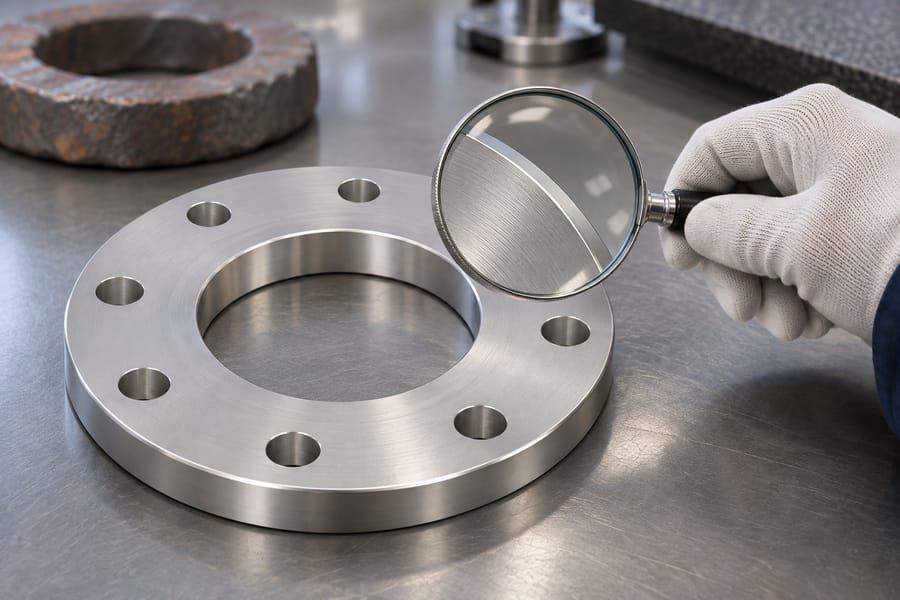
Visual inspection is commonly used to identify accessible surface irregularities, including visible cracks, laps, folds, scale pits, and machining damage. Surface preparation and lighting conditions influence the ability to observe smaller indications.
Visual examination can also identify obvious forging irregularities, damaged edges, incomplete features, and surface conditions that require further evaluation. However, it cannot establish the absence of concealed internal discontinuities.
Dimensional inspection verifies whether the finished flange conforms to its approved drawing and applicable dimensional standard. Relevant features include outside diameter, thickness, bore, bolt-hole arrangement, facing dimensions, and other specified machining details.
Measurement datums and methods should be consistent with the drawing. For example, bolt-hole positioning must be checked against the specified reference geometry, while sealing-face measurements should reflect the requirements for the selected facing configuration.
Magnetic Particle Testing (MT)
Magnetic particle testing uses a magnetic field and suitable particles to reveal discontinuities that interrupt magnetic flux at or near the material surface. It is applicable only to ferromagnetic materials.
The method can help identify surface and near-surface cracks, laps, and similar discontinuities. Its effectiveness depends on appropriate magnetization, examination direction, surface condition, and the sensitivity of the selected procedure.
A discontinuity aligned with the field can produce a weak response, which is why magnetization direction matters. Multiple magnetization directions may therefore be required under the applicable examination procedure.
Material classification should be confirmed before selecting MT. Stainless steel designations alone are not sufficient to determine suitability because magnetic response varies with material structure and composition.
Liquid Penetrant Testing (PT)
Liquid penetrant testing identifies discontinuities that are open to the examined surface. A penetrant enters accessible openings through capillary action, and a suitable development process makes relevant indications visible.
PT can be useful for suitable nonporous materials, including materials that cannot be examined through magnetic particle testing. Its application depends on surface condition, cleanliness, penetrant compatibility, and the specified examination procedure.
The method cannot reliably identify discontinuities that remain entirely beneath the surface. It also does not directly establish defect depth, so additional examination may be necessary when depth or internal extent affects acceptance.
Surface preparation is particularly important because oil, paint, machining residues, and other contaminants can obstruct openings or interfere with examination results. The procedure should specify the required cleaning and examination sequence.
Examining the Interior with Ultrasound
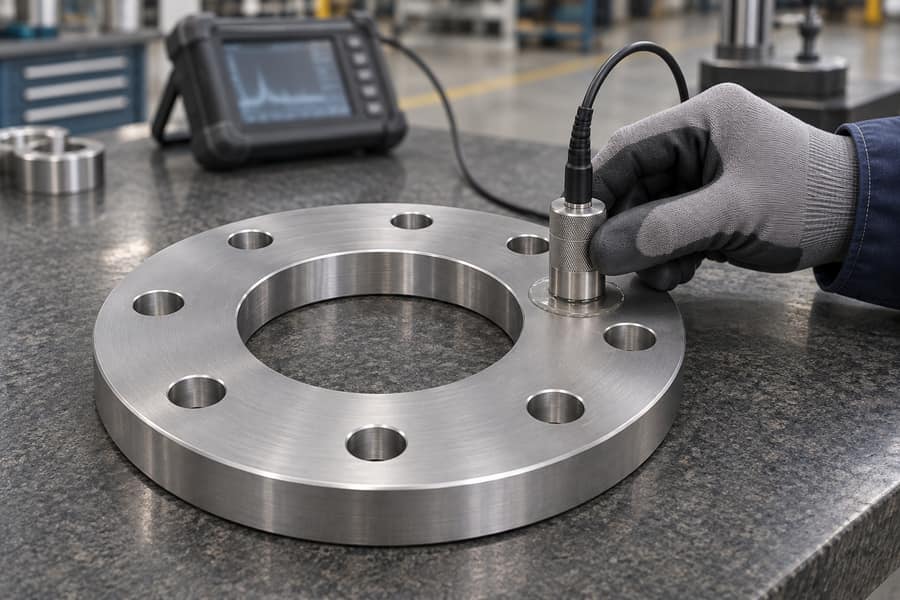
An ultrasonic probe introduces short acoustic pulses into the steel, and the returning signals help an examiner assess its interior. Reflections from internal interfaces can indicate discontinuities, allowing examination of regions that visual methods cannot assess.
UT may be used to investigate internal cracks, cavities, inclusions, and other discontinuities when the selected technique is appropriate. Detection performance depends on material structure, thickness, surface access, and discontinuity orientation.
Forged flange geometry can make examination more complicated than testing a simple flat plate. Hubs, neck transitions, changes in section thickness, and curved surfaces can influence sound paths and scanning coverage.
Probe selection, calibration, reference standards, scanning directions, and interpretation criteria should be established through a qualified examination technique. The procedure must demonstrate suitability for the actual component geometry and required inspection scope.
A general statement requiring ultrasonic testing does not establish that every internal region has been adequately examined. The purchase specification should identify examination coverage, applicable procedure, and acceptance requirements.
Inspection Indications and Defect Acceptance
An inspection indication is an observable response produced during examination. A discontinuity is an interruption or irregularity in the material, while a rejectable defect is a condition that fails the applicable acceptance criteria.
These terms describe different stages of evaluation. An indication may correspond to a harmless geometric feature, a non-relevant response, or a material discontinuity that requires further investigation before its acceptability can be determined.
Acceptance depends on the specifications and requirements invoked by the purchase order. Relevant documents may include the material specification, product standard, specified NDT procedure, approved drawings, and project-specific supplementary requirements.
Dimensional acceptance and pressure-temperature rating are also separate from NDT acceptance. A flange can satisfy its material examination requirements while still failing a dimensional requirement, or meet its dimensions while containing a rejectable discontinuity.
Defect Repair and Reinspection
Grinding and local material removal should not be treated as automatically acceptable repair methods. Removing a discontinuity changes the local geometry and may reduce the remaining thickness below the required dimension.
Before approving material removal, evaluate the defect location, depth, remaining section, and applicable drawing or product requirements. The proposed repair must comply with the invoked specification and any required purchaser authorization.
Welding repairs require additional consideration because they introduce localized heating and a new metallurgical condition. Where permitted, the repair should follow an approved procedure with the required material, process, heat-treatment, and inspection provisions.
After an authorized repair, reinspection should verify the repaired region using the method and acceptance criteria specified for that repair. Dimensional checks and supplementary NDT may also be necessary, depending on the original discontinuity and repair method.
Repair records should identify the defect location, authorization, repair procedure, inspection results, and final disposition. This documentation allows the purchaser to establish whether the finished flange meets the agreed requirements.
| Inspection method | Detection scope | Main limitation |
| Visual testing | Visible surface irregularities, cracks, and machining damage | Cannot establish internal soundness |
| Dimensional inspection | Geometry, dimensions, and machining deviations | Does not detect internal discontinuities |
| Magnetic particle testing (MT) | Surface and near-surface discontinuities | Applicable only to ferromagnetic materials |
| Liquid penetrant testing (PT) | Surface-breaking discontinuities | Cannot detect discontinuities that are not open to the surface |
| Ultrasonic testing (UT) | Internal discontinuities | Detection depends on qualified technique, material, and geometry |
Manufacturing Controls and Requirements for Preventing Forged Flange Defects
Defect prevention is more effective when quality controls are established at each manufacturing stage. Incoming material verification, forging process control, heat-treatment records, and machining inspection address different sources of nonconformity.
Incoming Material and Billet Quality Control
Incoming material verification establishes whether the billet or starting material matches the specified grade and purchase requirements. Keep each component linked to its original heat and batch records as it moves between production and inspection stages.
Material certificates should be reviewed for the required heat identification, chemical composition, and mechanical property information. The inspection scope should reflect the material specification and any additional quality requirements included in the purchase order.
Visual checks and appropriate incoming examinations can help identify surface damage or material conditions requiring further evaluation. Billet dimensions and condition should also be reviewed before cutting and heating operations begin.
These controls are particularly relevant when the order specifies different material families, such as carbon steel, stainless steel, alloy steel, or duplex steel. Requirements should be confirmed for the actual grade rather than generalized across all materials.
Forging Process and Temperature Control
Forging process control focuses on maintaining suitable metal flow and deformation throughout the component. Billet preparation, heating uniformity, die condition, and forming sequence all influence the quality of the resulting forging.
Temperature control is important because material flow and deformation behavior change with temperature. Conditions that are unsuitable for the specified material may contribute to cracking, incomplete die filling, or other forging discontinuities.
Die inspection should address alignment, wear, and surface condition. Changes in die geometry can affect material distribution and produce recurring problems such as mismatch, underfill, or localized folds.
Descaling and intermediate surface checks provide additional control over oxidation-related defects. Examining the forging before subsequent operations helps identify visible discontinuities while their location and extent remain accessible.
Heat-Treatment and Machining Verification
Heat-treatment controls should be based on the applicable material requirements rather than a single procedure applied to every steel grade. Heating, holding, and cooling conditions must correspond to the required material condition.
Furnace records and material traceability help connect the finished flange with its processing history. Where specified, mechanical property verification provides evidence that the required material characteristics have been achieved.
Machining verification should begin with approved drawings and clearly established reference datums. Fixture positioning, tooling condition, and machining sequence should be controlled to maintain the required relationship between the bore, bolt holes, flange face, and other features.
Final measurements should cover critical dimensions and sealing geometry. Particular attention should be given to features that influence assembly compatibility, including bolt-hole layouts, facing dimensions, and RTJ groove requirements.
Material Specifications, Dimensional Standards, and Pressure Ratings
Forged flange requirements involve several types of specifications that serve different purposes. Confusing them can result in an order that identifies a material grade but leaves important dimensional, rating, or assembly requirements unresolved.
Grade document:
Sets the chemistry limits, property requirements and delivery condition for the chosen steel. ASTM material specifications may be used where appropriate to the selected material and project.
Dimensional standard:
Establishes applicable flange geometry, dimensions, facing configurations, and related requirements. ASME flange standards and applicable EN standards should be identified by their specific designation and edition.
ANSI is associated with standards approval and accreditation activities; it should not be described as the organization that independently writes every ASME flange standard. Similarly, DIN and EN designations should be identified accurately rather than treated as automatically interchangeable dimensional requirements.
Pressure-temperature rating:
Defines the pressure capacity associated with the applicable standard, material group, pressure class, and temperature. A nominal pressure class should not be interpreted as one fixed allowable working pressure at every temperature.
Design pressure and design temperature are specified engineering conditions used for piping-system design and component selection. They are not necessarily the same as ordinary operating pressure and temperature readings, which may normally be lower.
Flange selection should use the applicable design conditions and the relevant pressure-temperature rating rules. A lower normal operating reading does not, by itself, justify selecting a lower-rated flange, while operating excursions beyond design conditions require separate engineering assessment.
Assembly requirements:
Address gasket selection, bolting, flange alignment, tightening procedures, and relevant piping-system requirements.
These factors affect the assembled joint and should not be confused with the material or dimensional specification of the flange itself.
Material grade, dimensional standard, pressure-temperature rating, and assembly requirements should therefore be reviewed together. A material specification does not independently establish flange dimensions, and a dimensional standard does not replace the need to verify material suitability.
Not every material and dimensional combination is necessarily available or permitted under every standard. The specified grade, flange configuration, size, rating, and applicable standard should be checked together before production is confirmed.
Inspection Requirements and Manufacturing Documentation
Inspection requirements should be defined before production begins. Before ordering, state which examinations are required, how much of the part they cover, what constitutes rejection and which records must accompany delivery.
Where MT, PT, or UT is required, the applicable procedure and acceptance requirements should be stated clearly. The inspection method must suit the material and expected discontinuity rather than being selected solely because it appears on a general inspection list.
Dimensional reports should address the drawing-controlled features, while material and heat-treatment records should maintain traceability to the finished component. NDT reports should identify the examination scope and relevant acceptance results.
Repair authorization and reinspection requirements should also be established. This avoids uncertainty when an indication is discovered during manufacturing or final examination and requires an engineering disposition.
Documentation should provide a consistent record connecting material identification, forging operations, heat treatment, machining, inspection, and final acceptance. The required records should be agreed with the purchaser according to the applicable project specification.
Forged Flange Manufacturing Scope at Boberry Machining
Boberry Machining supplies forged flanges in carbon steel, stainless steel, alloy steel, and duplex steel, with material and configuration requirements confirmed for individual orders.
Available flange configurations include weld-neck, slip-on, blind, and other connection styles. Orders can specify an RF land, an FF contact plane or an RTJ ring seat, with the finished detail confirmed against the drawing.
Custom requirements can cover bore dimensions, bolt-hole layouts, sealing-face geometry, and other machining details based on approved drawings. Release the manufacturing order only after the grade, interface drawing, rating basis and examination plan have been reconciled.
For an accurate manufacturing inquiry, provide the material grade and specification, flange type, nominal size, pressure class, applicable dimensional standard, facing configuration, and operating or design conditions. Include the approved drawing, machining requirements, heat-treatment requirements, and specified NDT acceptance criteria.
Where project documentation requires material traceability, inspection reports, or repair authorization records, identify those requirements in the inquiry. This gives Boberry Machining a defined basis for confirming the requested forged flange configuration and its manufacturing and inspection requirements.
| Manufacturing stage | Main quality risks | Key preventive controls |
| Raw material preparation | Inclusions, porosity, material inconsistencies | Material verification, billet inspection, and traceability |
| Heating and forging | Laps, folds, cracks, underfill, and die mismatch | Temperature, deformation, descaling, and die control |
| Heat treatment | Cracking, distortion, and hardness variation | Material-specific procedures and controlled heating and cooling |
| Machining | Dimensional deviations and sealing-surface damage | Datum control, fixture alignment, tooling checks, and measurement |
| Final inspection | Undetected or incorrectly classified nonconformities | Appropriate visual, dimensional, and NDT examination with defined acceptance criteria |