
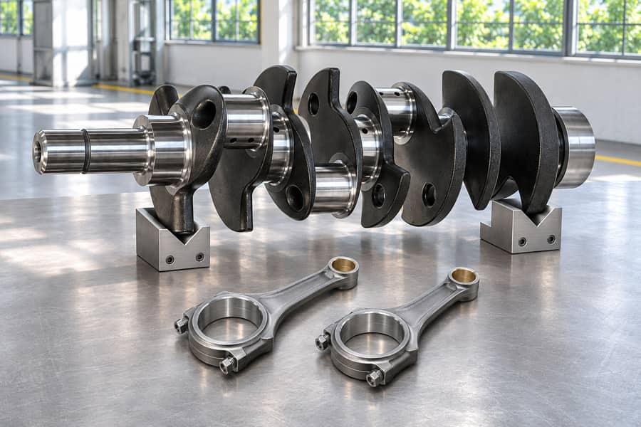
Common drop forged parts used in industrial applications include connecting rods, selected crankshafts, compact shafts, yokes, gear blanks, hooks, shackles, levers, and brackets. Their shapes reflect distinct industrial loading requirements.
Drop forging uses hammer impacts to deform heated metal. Finished suitability depends on component geometry, material selection, machining, inspection, and whether another manufacturing route better fits the design.
What Are Drop Forged Parts?
Drop forged parts are metal components shaped by repeated or controlled hammer impacts, typically while the material is heated. The process produces preforms that may require additional finishing.
Drop hammers form one branch of the industrial hammer-forging family. Depending on equipment and terminology, the hammer may fall under gravity or receive additional energy from a powered mechanism.
Unlike press forging, which applies force through a press stroke, hammer forging delivers energy through impacts. Both approaches can produce industrial components with different tooling arrangements.
Tooling is a separate distinction:
- Open-die forging: Metal deforms between relatively simple dies without being fully enclosed in a shaped cavity.
- Impression-die forging: Shaped die cavities guide metal deformation and may allow excess material to form flash.
- Closed-die terminology: Often overlaps with impression-die forging, although strictly flashless closed-die forging contains the metal without intentional flash formation.
The appropriate configuration depends on component geometry, stock dimensions, material behavior, and production requirements.
Boberry Machining’s drop forging services can be considered when a component’s geometry and production requirements suit hammer-based forming. However, not every industrial forging is manufactured using drop forging.
Connecting Rods and Crankshafts
Connecting Rods
Connecting rods are common components in engines, compressors, and other reciprocating machinery. They transfer forces between moving components while experiencing alternating tensile and compressive loading.
Their geometry usually includes an elongated body with enlarged ends for mechanical connections. Forging produces a preform that distributes material around these functional regions.
The transitions between the rod body and enlarged ends deserve particular attention. Abrupt section changes can increase local stresses under repeated loading.
Several features require downstream manufacturing operations:
- Bearing bores: Precision machining establishes the required diameter, roundness, and alignment.
- Cap joint: On a split rod, the cap must locate correctly against the body, with a fastening design suited to the operating load.
- Critical transitions: Specified surface conditions and geometry help control local stress concentrations.
- Dimensional inspection: Measurements verify that finished features meet the component drawing.
Forging does not independently establish fatigue performance. Material quality, deformation history, heat treatment, surface condition, and final dimensions all influence the finished component.
Crankshafts
Crankshafts convert reciprocating motion into rotation or perform the reverse function in mechanical equipment. They are used in engines, compressors, pumps, and related assemblies.
During operation, crankshafts experience combinations of torsion, bending, and cyclic forces. Their geometry includes main journals, crankpins, crank throws, and sometimes counterweights.
Selected crankshaft designs can be manufactured through drop forging when their dimensions and shapes suit hammer forming. Larger or more complex designs may require other forging routes.
Critical manufacturing features include:
- Bearing journals: Require controlled diameter, surface finish, and geometric accuracy.
- Crankpins: Need accurate positioning relative to the main shaft axis.
- Fillet regions: Require suitable geometry because stresses can concentrate at section transitions.
- Rotational alignment: Runout and related dimensional requirements affect assembly and operation.
Machining and grinding establish the finished journal dimensions and contact surfaces. Inspection must address the specified geometry rather than relying on the forging operation alone.
Connecting rods primarily transmit reciprocating forces, while crankshafts combine rotational torque transmission with offset loading. These differences influence forging geometry, machining requirements, and component evaluation.
Compact Shafts, Yokes, and Transmission Components
Compact Shafts and Spindles
Compact shafts and spindles transfer rotational motion between mechanical components. They are found in industrial drives, power transmission equipment, and machinery assemblies.
These components primarily experience torsion, although bending and cyclic loads may also occur. Their geometry often includes shoulders, stepped diameters, or enlarged connection regions.
Forging can establish these larger features before precision machining. However, the as-forged shape normally does not provide every dimension required for final assembly.
Typical finishing requirements include:
- Bearing seats: Machined to achieve specified diameter, roundness, and surface finish.
- Splines and keyways: Produced to create reliable mechanical connections.
- Threaded sections: Machined where fasteners or adjustment mechanisms are required.
- Shoulders: Finished to establish accurate axial positioning of mating components.
For compact components, drop forging may provide a suitable shaped preform. Large industrial shafts often require open-die forging or press-based methods instead.
Boberry Machining’s forged shafts are relevant to projects requiring appropriate stock shaping, material selection, and subsequent machining, although the production route must be evaluated for each design.
Yokes and Forked Components
Yokes connect rotating or articulated components in universal joints, mechanical linkages, and other industrial assemblies. Their forked geometry transfers forces through pins or mating connections.
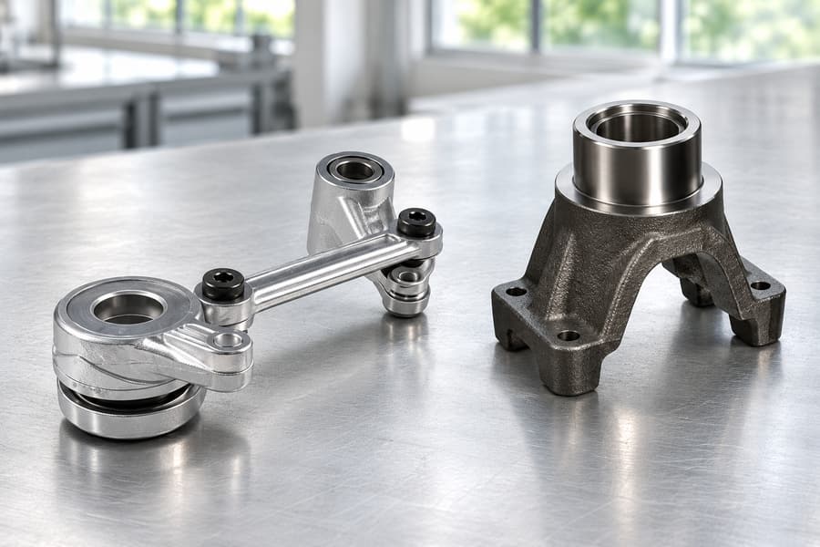
The spacing between fork arms and the alignment of pin holes influence assembly performance. Uneven geometry can introduce undesirable loading during operation.
Forging creates the general forked shape, while machining establishes critical bores, contact surfaces, and connection dimensions. Material distribution around the fork roots also requires consideration.
Gear Blanks and Coupling Hubs
Gear blanks serve as starting components for gears used in industrial transmissions and gearboxes. Their purpose is to provide suitable material for producing the finished gear geometry.
A forged gear blank does not necessarily contain finished gear teeth. Depending on design requirements, teeth may be produced through hobbing, shaping, milling, or other operations.
Additional machining commonly establishes central bores, keyways, mounting faces, and concentric features. Heat treatment and finishing depend on the specified material and operating conditions.
Coupling hubs perform a related transmission function by connecting shafts or rotating assemblies. Their critical features include connection geometry, concentricity, and suitable transitions between sections.
Boberry Machining’s forged gears provide a relevant product category for evaluating gear-related forgings, including the distinction between shaped blanks and finished machined components.
Hooks, Shackles, and Industrial Eye Hardware
Forged Hooks
Forged hooks are used in material-handling equipment and industrial attachment assemblies. Their curved geometry allows forces to be transferred through a defined connection region.
A hook experiences tension together with bending, particularly around its curved body. The direction of loading affects stress distribution and potential deformation.
Important geometric considerations include throat opening, cross-sectional transitions, and material distribution around curved regions. These features must match the intended application.
Drop forging may be appropriate for selected hook designs, but not every forged hook uses this process. Equipment, tooling, and component requirements determine the manufacturing route.
Shackles and Connecting Hardware
Shackles connect mechanical components through a removable pin and shaped body. Common configurations include bow-shaped and straight-body designs used in industrial connections.
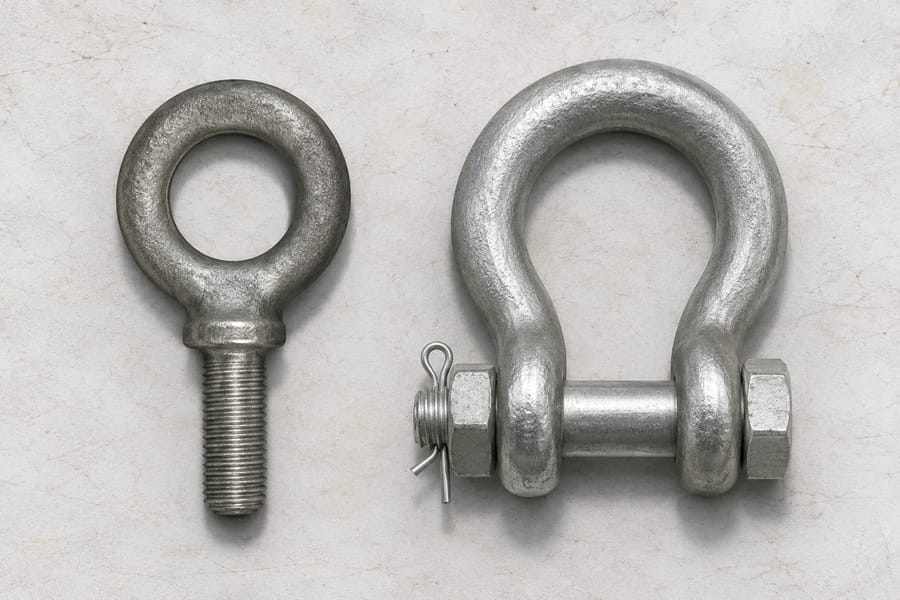
The shackle body transfers loads toward the pin connection. Pin-hole geometry, body alignment, and section transitions influence how forces are distributed.
Machining may be necessary to establish accurate pin interfaces, threaded connections, or other mating features. Inspection requirements depend on the intended operating conditions.
A forged appearance does not establish a working load limit or safety certification. Such claims require appropriate product design, verification, testing, and applicable documentation.
Eye Bolts and Eye-Shaped Fittings
Eye bolts and related fittings provide attachment points for mechanical connections. Their design generally combines a loop-shaped section with a shank or threaded connection.
These components experience tension and may encounter bending when forces act outside the intended loading direction. Eye geometry and shank transitions therefore require attention.
Forging can form the eye-shaped preform, while machining establishes threads and critical mating surfaces. Material specifications and finished-part acceptance criteria remain essential.
Levers, Brackets, and Mechanical Linkage Parts
Industrial Levers and Control Arms
Industrial levers and control arms transfer motion or mechanical force between connected parts. They are commonly used in machinery controls, actuating mechanisms, and linkage assemblies.
Their geometry may include curved profiles, enlarged ends, and locally thickened sections. These features accommodate pivot connections and changing force directions.
During operation, levers experience bending and concentrated loads around pivot points. Repeated movement can also introduce fatigue considerations at critical sections.
Forging produces the basic component shape, while machining establishes pivot bores, contact surfaces, and other precise connection features.
Mounting Brackets and Support Components
Mounting brackets connect machinery components to supporting structures. Depending on the installation, they may experience bending, shear, tension, or combinations of these loads.
Forged brackets can incorporate mounting bosses, reinforced regions, and changes in section thickness. Their design must accommodate both service loading and manufacturing constraints.
Bolt holes, threaded connections, and mounting faces generally require finishing. The selected manufacturing route should reflect component dimensions, geometry, and production quantity.
Linkage Forks and Connecting Fittings
Linkage forks connect articulated components through pins or similar mechanical joints. Unlike many torque-transmitting yokes, these fittings primarily transfer forces through linkage movement.
Important features include fork spacing, pin-hole alignment, and the geometry surrounding loaded connections. Bending and localized bearing forces affect component requirements.
Machining and inspection establish the necessary mating dimensions. The forging process must also accommodate the fork geometry without creating unsuitable material distribution.
Comparison of Common Drop Forged Parts and Their Applications
Industrial forged components differ in loading conditions, functional geometry, and finishing requirements. These differences are more useful for component selection than broad claims about forging strength.
The following table summarizes common part families that may be manufactured through drop forging when their designs and production requirements permit.
| Drop Forged Part | Typical Industrial Application | Main Service Loads | Critical Features |
| Connecting rods | Engines and compressors | Alternating tension and compression | Bearing bores, alignment |
| Selected crankshafts | Reciprocating machinery | Torsion, bending, fatigue | Journals, fillets |
| Compact shafts | Industrial transmissions | Torsion and bending | Bearing seats, splines |
| Yokes | Universal joints and linkages | Torque, bending, bearing loads | Fork geometry, pin bores |
| Gear blanks | Gearboxes and drives | Torsion and cyclic gear loads | Bore, finished tooth geometry |
| Hooks | Material-handling equipment | Tension and bending | Curved section, throat geometry |
| Shackles and eye hardware | Mechanical attachment systems | Tension, possible bending | Pin holes, eye geometry, threads |
| Levers and brackets | Industrial machinery | Bending, shear, cyclic loading | Pivot points, mounting faces |
How Service Loads Affect Component Requirements
Service loads help determine material selection, section geometry, machining requirements, and inspection scope. A component designed for torque transmission has different priorities from a tensile connection.
For example, shaft applications often emphasize torsional capacity and mating accuracy. Hooks require particular attention to curved sections and the direction of applied forces.
Connecting rods and crankshafts experience repeated loading cycles, making fatigue-sensitive geometry and material condition especially important. Inspection requirements should reflect these operating conditions.
The appropriate design depends on the complete specification rather than the forging method alone. The words “drop forged” cannot tell a buyer how much load a particular part can carry or how long it will last.
Materials and Manufacturing Requirements for Drop Forged Parts
Common Material Options
Material selection depends on mechanical loading, environmental exposure, machining requirements, and the intended heat-treatment condition. Different component families may use different grades within the same material category.
- Carbon steel: Used for selected brackets, levers, connecting components, and general industrial hardware. Suitability depends on grade, processing condition, and required properties.
- Alloy steel: Considered for shafts, connecting rods, gear blanks, and other components requiring specified strength, hardenability, toughness, or fatigue properties.
- Stainless steel: Used for selected components requiring corrosion resistance. Mechanical properties and heat-treatment responses vary significantly between stainless steel families.
Material selection must also account for section thickness and the finished component’s operating environment. A suitable grade for one application may be inappropriate for another.
Main Manufacturing Steps
The production sequence depends on part geometry, tooling arrangements, material grade, and finishing requirements. Common operations involved in manufacturing drop-forged components include the following.
- Material preparation: Select the specified material and cut billets to dimensions appropriate for the forging sequence.
- Heating: Bring the material to a suitable forming temperature while controlling heating conditions.
- Hammer forming: Apply controlled hammer impacts using dies designed for the required component geometry.
- Trimming: Remove flash when it is produced by the selected impression-die process.
- Heat treatment: Apply alloy-appropriate processing when required by the material specification and intended properties.
- Cleaning: Remove scale and prepare the forged surface for further operations or inspection.
- CNC finishing: Machine bores, threads, journals, splines, mounting surfaces, and other precision features.
Some components may require additional operations, including grinding or specialized finishing. The sequence should reflect the finished drawing rather than follow an identical process for every component.
Machining and Quality Inspection
Drop forging establishes the general component shape, but functional surfaces frequently require additional machining. This distinction is important when reviewing tolerances and manufacturing quotations.
Bearing journals, pin bores, threads, and mounting faces often need tighter dimensional control than the initial forged preform provides.
Inspection may include dimensional measurement, material verification, surface examination, and specified nondestructive testing. The appropriate methods depend on component requirements and acceptance criteria.
For parts exposed to cyclic or safety-critical loading, inspection requirements may be more demanding. These requirements should be defined through applicable specifications rather than assumed from the forging process.
How to Select the Right Forging Process for Industrial Parts
When Drop Forging Is Suitable
Drop forging is worth considering for components with repeatable geometries that suit hammer forming. Shaped preforms can incorporate enlarged sections, shoulders, and other functional features.
The process is particularly relevant when anticipated production quantities justify tooling development and setup. However, tooling investment must be considered alongside material utilization and finishing costs.
Complex geometry does not automatically make drop forging the preferred route. Component dimensions, access for forming, die design, and material flow all affect feasibility.
The forging drawing should leave enough stock at each cutting surface to achieve the finished size without exposing an undersized region. A near-net preform may reduce some machining, but precision features still require appropriate finishing.
Drop Forging Versus Other Manufacturing Methods
Different manufacturing methods can produce components with similar finished functions. The preferred route depends on geometry, material, production volume, mechanical requirements, and total accepted-part cost.
| Component Requirement | Manufacturing Route to Consider | Main Selection Factor |
| Compact shaped components | Impression-die drop forging | Geometry, tooling, production quantity |
| Relatively simple forged preforms | Open-die forging | Geometric flexibility, machining allowance |
| Large or elongated shafts | Open-die or press forging | Dimensions, deformation requirements |
| Large seamless rings | Ring rolling | Annular geometry, dimensional requirements |
| Parts with complex internal cavities | Casting | Geometric complexity, defect acceptance |
| Low-volume machined components | Machining from stock | Setup, material utilization, total cost |
Open-die forging may use hammer or press equipment, while impression-die forging can also employ different force-application systems. These classifications describe different aspects of manufacturing.
Casting may accommodate internal cavities that would complicate forging. Machining from stock can avoid dedicated forging tooling, although material removal and processing costs must be considered.
Process comparisons should use equivalent material specifications, finished geometries, required properties, and acceptance conditions. No single route consistently guarantees better strength, accuracy, or pricing.
Key Information for Industrial Component Procurement
Clear technical information helps manufacturers assess production feasibility and define an appropriate manufacturing scope. Incomplete drawings can make process comparisons and quotation evaluation difficult.
For a meaningful technical review, engineers and procurement teams should provide:
- Component drawings: Include finished dimensions, geometric tolerances, critical surfaces, and functional connections.
- Material specifications: Identify the required material grade, mechanical properties, and applicable technical standards.
- Service conditions: Describe loading direction, cyclic stresses, operating temperature, and environmental exposure.
- Finishing requirements: Specify machining, heat treatment, surface finish, and required inspection procedures.
- Production requirements: Provide anticipated quantities, delivery expectations, and any relevant manufacturing constraints.
These details help determine whether a component is suitable for drop forging or would benefit from another production method.
Engineers and procurement teams can review component drawings, material specifications, manufacturing routes, and finishing requirements with Boberry Machining to establish an appropriate production approach.