
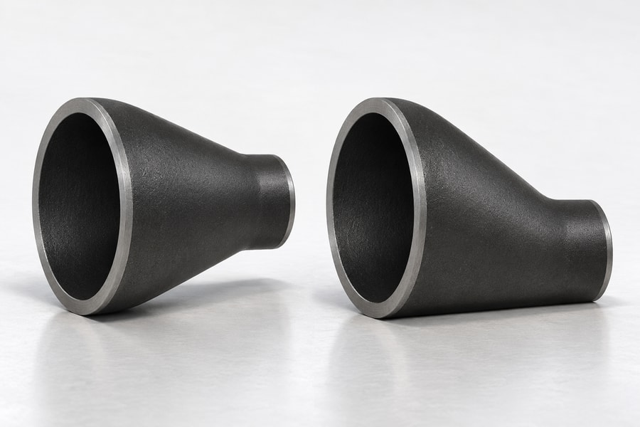
Cast reducers connect pipes of different nominal sizes, but their geometry also changes centerline alignment and the internal flow transition.
Concentric and eccentric designs create different installation and operating considerations, so selection must account for flow direction, pipe orientation, fluid behavior, design requirements, and connected equipment within the complete piping arrangement.
Concentric vs. Eccentric Cast Reducers: Structural Differences
The primary difference between concentric and eccentric cast reducers is the relationship between their inlet and outlet centerlines. Although both designs connect pipes of different diameters, their geometries produce different internal profiles and installation requirements.
Understanding this distinction helps engineers evaluate equipment alignment, flow transitions, elevation changes, and potential air or liquid accumulation. The appropriate configuration depends on the piping layout rather than diameter reduction alone.
Concentric Cast Reducer Design
A concentric cast reducer has inlet and outlet sections that share a common longitudinal centerline. Its transition is symmetrical, with the pipe diameter decreasing or increasing uniformly around that centerline.
This geometry produces a centered transition between adjoining pipes. When installed in a vertical pipeline, the reducer can maintain the same central axis while accommodating different nominal diameters.
Concentric reducers are commonly considered for vertical piping, symmetrical equipment connections, and arrangements where maintaining centerline alignment is important. Their geometry can simplify dimensional coordination with connected components.
However, symmetrical construction does not automatically make a concentric reducer suitable for every vertical or horizontal application. Engineers must still evaluate fluid behavior, flow direction, elevation changes, and the possibility of trapped air or retained liquid.
Eccentric Cast Reducer Design
An eccentric cast reducer has inlet and outlet sections with offset longitudinal centerlines. Unlike a concentric design, its transition is asymmetrical, creating one relatively flat side when the fitting is installed in a specified orientation.
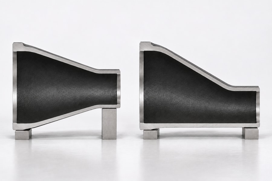
The flat side can be positioned upward or downward, depending on the piping arrangement. This characteristic allows engineers to manage the relationship between the upper and lower internal surfaces of adjoining pipes.
Flat-on-top installation is common in horizontal liquid pump suction arrangements because it helps avoid creating a high point where air can accumulate. Nevertheless, the complete suction layout, approach piping, venting provisions, and equipment requirements must determine the final orientation.
Flat-on-bottom installation may be considered when maintaining the pipe invert or coordinating a drainage arrangement is important. Its suitability depends on the required slope, fluid characteristics, solids content, and downstream configuration.
Eccentric reducers are therefore useful when the piping system requires deliberate control of elevation or internal geometry. Their asymmetrical construction provides installation flexibility, but incorrect orientation can introduce unwanted high or low points.
Key Differences Between the Two Designs
Both reducer types perform the same basic dimensional transition, but they address different geometric requirements. Concentric reducers preserve a shared centerline, whereas eccentric reducers introduce a controlled offset between adjoining pipe sections.
The distinction becomes particularly important in horizontal piping, where the upper and lower surfaces influence air management, drainage, and equipment connections. Engineers should compare these characteristics before finalizing the fitting configuration.
| Comparison Factor | Concentric Reducer | Eccentric Reducer |
| Geometry | Symmetrical transition | Asymmetrical transition |
| Centerline | Common longitudinal centerline | Offset longitudinal centerlines |
| Diameter transition | Uniform around the centerline | Uneven relative to the centerline |
| Installation orientation | No inherent flat-side orientation | Requires consideration of flat-side position |
| Main design consideration | Centerline alignment and transition geometry | Elevation, air management, and drainage |
| Typical application consideration | Vertical piping and symmetrical equipment layouts | Horizontal piping with specific elevation requirements |
These differences are design considerations rather than universal application restrictions. Either configuration requires verification against the actual operating conditions, connection dimensions, and applicable piping design requirements.
How Reducer Geometry Affects Flow and Installation
Reducer geometry influences how fluid moves between different pipe diameters and how the fitting interacts with the surrounding piping arrangement. Its effects depend on flow direction, transition geometry, fluid properties, and installation orientation.
Flow Direction, Velocity, and Pressure Loss
When liquid flows from a larger pipe into a smaller pipe, its average velocity generally increases if the flow rate remains constant and density changes are negligible. For a steady incompressible stream, the volume passing each cross-section per unit time remains the same: Q = A × V.
In this expression, Q is volume per unit time, A is the bore area at the section being examined, and V is the section’s mean velocity. With Q held constant, reducing the bore area leaves the liquid moving faster.
The resulting pressure behavior depends on both the velocity change and irreversible losses within the fitting. Reducer geometry, diameter ratio, taper length, surface condition, and flow regime all influence the actual hydraulic response.
During contraction from a larger diameter to a smaller diameter, static pressure generally decreases as velocity increases. The reducer profile and adjacent piping determine how large the pressure change becomes.
When flow travels in the opposite direction, the reducer functions as an expanding passage. Velocity decreases as the flow area increases, allowing some static-pressure recovery downstream of the transition.
Static-pressure recovery must not be confused with the elimination of pressure loss. Expansion can recover part of the static pressure, but turbulence, flow separation, and friction produce an irreversible reduction in total pressure.
The U.S. Department of Energy’s fluid-flow guidance provides a useful framework for evaluating local losses through fittings. Engineers can use appropriate loss coefficients and reference velocity conditions when estimating system pressure requirements.
However, a coefficient established for one reducer geometry or flow direction should not automatically be applied to another configuration. Reliable calculations require suitable hydraulic data or an appropriate engineering basis for the specified fitting.
Air Pockets and Liquid Accumulation in Horizontal Piping
Air management is an important consideration in horizontal liquid pipelines. Changes in internal elevation can create local high points where gas accumulates, potentially affecting flow stability and the operating conditions of connected equipment.
A concentric reducer maintains a common centerline, but its upper and lower internal surfaces do not remain level when adjoining pipes have different diameters. Depending on the installation direction, this geometry can introduce a local high point or low point.
An eccentric reducer provides another option by allowing one internal side to remain approximately aligned across the transition. With the flat side positioned upward, the arrangement is commonly used to reduce the likelihood of air accumulation in horizontal pump suction piping.
This orientation is not a substitute for proper suction-piping design. Engineers must also consider the complete approach arrangement, pipe slope, pump nozzle elevation, required straight lengths, venting provisions, and possible high points elsewhere in the system.
Drainage requirements can lead to a different orientation. A flat-on-bottom eccentric reducer may help maintain a consistent pipe invert, depending on the adjoining pipe slopes and the intended drainage path.
Solids-bearing pipelines introduce additional considerations. Deposits may collect in low areas or around unfavorable internal transitions, particularly when operating velocity, particle characteristics, or cleaning arrangements are unsuitable.
Consequently, reducer orientation should be evaluated alongside the entire piping route. Selecting a flat-side position based only on the reducer itself can overlook downstream elevations, maintenance access, and other potential accumulation points.
Installation in Vertical and Horizontal Pipe Runs
Vertical piping often uses concentric reducers because their common centerline supports symmetrical alignment between connected pipe sections. This arrangement can also simplify coordination with vertically aligned equipment nozzles and other fittings.
Nevertheless, concentric geometry does not automatically establish suitability for vertical service. Engineers should examine flow direction, fluid properties, gas release, drainage requirements, and the possibility of liquid retention during shutdown.
Horizontal piping generally requires more attention to the relative positions of the upper and lower internal surfaces. The choice between concentric and eccentric geometry should reflect whether air management, drainage, invert alignment, or equipment connection takes priority.
Installation direction also matters. A reducer connecting a pump, tank, heat exchanger, or process line may have different requirements depending on whether it is installed on the suction side, discharge side, or within an independent transfer line.
Connected pipe supports must accommodate the resulting geometry without forcing the reducer into position. Misalignment introduced during installation can transfer unwanted loads to the fitting, adjoining joints, and equipment nozzles.
For this reason, the piping drawing should identify the reducer type, flow direction, orientation, and relevant elevation references. These details reduce ambiguity during fabrication, installation, and inspection.
Reducer Selection Under Different Piping Conditions
The following comparison illustrates how different piping conditions influence reducer selection. These are general engineering considerations, not mandatory rules that replace project specifications or equipment requirements.
| Piping Condition | Main Engineering Concern | Design Consideration |
| Horizontal liquid pump suction | Potential air accumulation | Flat-on-top eccentric orientation is common; verify the complete suction approach and venting arrangement. |
| Horizontal drainage piping | Liquid retention and elevation continuity | Evaluate flat-on-bottom arrangements where maintaining the pipe invert is important. |
| Solids-bearing pipelines | Sediment accumulation and cleaning | Assess internal transitions, operating velocity, drainage, and maintenance requirements. |
| Vertical piping | Centerline alignment | Consider concentric geometry while checking flow direction and drainage requirements. |
| Equipment nozzle connections | Alignment and external loading | Coordinate reducer geometry with nozzle dimensions, support locations, and installation clearances. |
The Hydraulic Institute provides relevant guidance on pump suction arrangements and reducer orientation. Its recommendations should be applied within the context of the complete pump installation rather than treated as isolated fitting-selection rules.
Key Engineering Factors in Cast Reducer Selection
After identifying the appropriate geometry, engineers must verify that the reducer meets dimensional, mechanical, and operating requirements. Use the results to decide whether the reducer will mate correctly and carry the specified service loads.
Pipe Diameter Ratio and Transition Length
The first step is to identify the nominal sizes of the inlet and outlet pipes. Their diameter relationship determines the extent of the required transition and influences the reducer’s internal flow geometry.
The nominal size label is not a measurement of the clear bore. Wall thickness and the applicable pipe dimensions influence the available flow area, so hydraulic calculations should use the relevant internal dimensions.
Transition length is another important consideration. A longer transition generally produces a more gradual geometric change, while a shorter reducer creates a more compact installation and a steeper transition.
Neither configuration is automatically preferable. A gradual transition may be beneficial for certain flow conditions, but available installation space, equipment clearance, manufacturing constraints, and pressure-loss requirements must also be considered.
Engineers should review the reducer dimensions together with adjoining elbows, valves, flanges, and equipment connections. Evaluating individual fittings without considering the complete layout can result in insufficient clearance or unexpected alignment problems.
Wall Thickness and Pressure Design
Wall thickness is a critical consideration because a cast reducer has a changing cross-sectional geometry. The thickness distribution must provide an appropriate structural basis throughout the transition and at both connection ends.
Unlike a straight pipe section, a reducer has different diameters and changing wall profiles. Casting geometry, core positioning, shrinkage, and subsequent machining can influence the actual dimensions of the finished component.
Pressure design should begin with the specified design pressure and design temperature rather than ordinary operating readings alone. Engineers must also account for the material grade and its applicable mechanical properties.
Corrosion allowance may be necessary when the conveyed medium can attack the material over the intended service period. Erosion, chemical exposure, temperature variation, and other operating conditions can also influence the required design basis.
The minimum actual wall thickness is more meaningful for structural verification than a nominal value considered without manufacturing tolerances. Inspection requirements should identify relevant measurement locations, particularly where the reducer transitions between different diameters.
Engineers should not assume that matching a connected pipe’s nominal wall designation automatically establishes reducer suitability. The fitting requires its own dimensional and engineering verification under the applicable product specification and design code.
Similarly, a reducer’s external appearance or nominal dimensions do not independently establish a pressure rating. Material properties, casting integrity, geometry, connection design, and required testing all contribute to the qualification of a pressure-containing component.
Mechanical Loads and Connection Compatibility
Internal pressure is only one source of loading in an industrial piping system. External forces, thermal expansion, equipment vibration, pipe weight, and installation misalignment can also affect the reducer and its connections.
Changes in flow area can produce unbalanced forces associated with pressure and momentum changes. The piping system must provide suitable support and restraint so that these forces do not create unacceptable loads on connected equipment or joints.
For ductile iron piping, the Ductile Iron Pipe Research Association distinguishes joint sealing from restraint against hydraulic thrust. A leak-tight joint should not automatically be assumed to provide the required mechanical restraint.
Engineers should therefore verify the actual connection type and its restraint characteristics. Anchors, restrained joints, supports, and other load-management provisions should be evaluated according to the system design and applicable requirements.
Connection compatibility also involves more than matching nominal pipe sizes. End dimensions, connection type, facing details, alignment tolerances, and installation clearances must be coordinated with adjoining components.
Where threaded, flanged, or welded connections are involved, the relevant connection requirements should be specified clearly. The reducer’s material, end preparation, and manufacturing condition must be compatible with the intended assembly procedure.
Material Selection and Applicable Standards for Cast Reducers
Material selection determines the mechanical and service-related characteristics of a cast reducer. Standards selection is equally important because fitting requirements depend on the manufacturing process, material, connection type, and intended application.
Comparing Common Casting Materials
Gray cast iron:
This material contains graphite in flake form, which influences its mechanical behavior. It offers useful casting and machining characteristics but has comparatively limited ductility and lower resistance to impact than ductile iron.
Gray cast iron is used in certain drainage and ventilation applications where the specified product and service conditions are suitable. Its use should not be extended automatically to pressurized industrial piping without an appropriate material and product qualification basis.
Ductile cast iron:
Its graphite forms nodules rather than flakes, producing improved ductility and toughness compared with conventional gray cast iron. That combination makes nodular iron worth evaluating when the reducer needs more tensile deformation capacity than gray iron provides.
However, the term ductile iron alone does not establish the suitability of a particular reducer. Engineers must verify the specified grade, casting quality, design conditions, connection requirements, and applicable product documentation.
Malleable cast iron:
Malleable iron is produced through heat treatment of white iron, changing its microstructure and improving its ductility. It has different manufacturing and mechanical characteristics from both gray and ductile cast iron.
Check the proposed grade against the reducer’s section sizes and duty before selecting it. Engineers should confirm that the specified material is appropriate for the reducer’s intended geometry and service rather than assuming interchangeability between cast iron categories.
Cast steel:
Cast steel uses a steel-based composition and offers mechanical properties determined by its grade, heat treatment, and manufacturing quality. Cast steel is one option to assess when the design calls for particular strength or impact properties.
Material selection should consider the complete operating environment, including pressure, temperature, corrosion, and mechanical loading. The material certificate and applicable specification should identify the actual grade rather than relying on a general description such as cast steel.
The following comparison summarizes the principal differences relevant to reducer selection.
- Gray cast iron: Consider its comparatively limited ductility and the intended application, particularly where non-pressurized drainage or ventilation is involved.
- Ductile cast iron: Evaluate its improved ductility and toughness against the specified pressure, temperature, and mechanical requirements.
- Malleable iron selection: Check the grade’s documented properties and whether the proposed reducer falls within its intended product scope.
- Cast steel: Assess grade-specific strength, toughness, heat treatment, and casting integrity requirements.
Understanding the Scope of ASME B16.9 and ASME B16.11
Standards must be selected according to the actual product form. A dimensional resemblance between two fittings does not establish that they belong to the same manufacturing category or meet identical qualification requirements.
ASME B16.9 covers factory-made wrought butt-welding fittings. Its scope relates to wrought fittings, so its dimensional requirements should not automatically be treated as a complete product specification for cast reducers.
ASME B16.11 covers forged fittings, including socket-welding and threaded configurations. Its scope is based on forged fitting products rather than cast components.
Consequently, a cast reducer that resembles a fitting dimensionally covered by either standard does not automatically comply with that standard. Its material, manufacturing process, pressure design basis, and inspection requirements need an appropriate qualification framework.
Connection standards should also be distinguished from pressure qualification. For example, ASME B1.20.1 addresses general-purpose inch pipe threads and their dimensional requirements, but thread conformity alone does not establish the pressure rating of a cast reducer.
Engineers should identify the governing piping design code, product specification, material requirements, and connection standards separately. This approach prevents a common specification error: using a familiar fitting standard without checking whether its scope covers the actual manufactured component.
Dimensional Inspection and Technical Specifications
Dimensional inspection confirms whether a reducer matches the approved drawing and can be assembled correctly. Material and casting-quality verification provide additional evidence that the supplied component meets its specified requirements.
Critical Dimensions to Verify
Dimensional verification should begin with the inlet and outlet sections because their sizes determine compatibility with adjoining pipes. The inspection should distinguish nominal size from the actual dimensions required by the connection design.
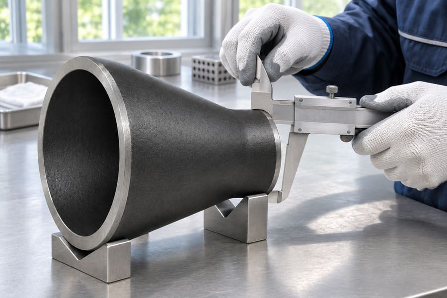
Overall length and centerline geometry are equally important. For eccentric reducers, the offset must be checked against the specified orientation, while concentric reducers require verification of the common centerline.
Depending on the connection type, the drawing should identify the relevant end dimensions and tolerances. Wall thickness should also be checked at specified locations rather than inferred from external measurements alone.
A practical dimensional inspection record can include the following items:
- Inlet and outlet dimensions: Verify nominal sizes and the specified connection-end dimensions.
- Overall length: Check the finished face-to-face or end-to-end dimension defined by the drawing.
- Centerline geometry: Confirm common centerline alignment or the specified eccentric offset.
- Orientation: Identify the flat-side position relative to the installation reference.
- Wall thickness: Measure the designated locations and compare the results with the applicable acceptance requirements.
- End preparation: Verify the specified flange, threaded, or welding-end configuration where applicable.
Inspection conditions should remain consistent with the approved drawing and measurement procedure. Datum selection, instrument accuracy, measurement location, and surface condition can all influence dimensional results.
Casting Quality and Material Verification
Casting quality affects the reliability and dimensional consistency of the finished reducer. Potential discontinuities include porosity, shrinkage cavities, inclusions, and other imperfections associated with the casting process.
Judge each discontinuity against the casting acceptance specification, taking account of its location and the reducer’s duty. A surface appearance check alone cannot establish the internal integrity of a pressure-containing casting.
Visual examination can identify certain surface defects, while additional inspection methods may be required for particular applications. The selection of non-destructive examination methods should account for the material, component geometry, defect type, and inspection objective.
Material verification should establish that the supplied component corresponds to the specified casting grade. Where required, material certificates, identification records, and traceability documentation should accompany the inspection package.
Pressure testing should only be specified when appropriate to the product design and applicable qualification requirements. A pressure test does not identify the alloy, measure every critical feature, or reveal every unacceptable casting discontinuity.
Information Required for a Custom Cast Reducer
A complete technical specification helps manufacturers evaluate the required geometry, material, manufacturing approach, and inspection scope. Drawings should communicate the intended configuration rather than leaving critical dimensions or orientation to interpretation.
For an engineering inquiry, buyers should prepare the following information before requesting a quotation or technical review:
- Reducer configuration: State whether a concentric or eccentric design is required.
- Pipe dimensions: Provide inlet and outlet nominal sizes and relevant actual connection dimensions.
- Overall geometry: Specify reducer length, centerline relationship, and eccentric offset where applicable.
- Installation orientation: Identify flat-side-up or flat-side-down requirements and the intended flow direction.
- Material specification: Identify the required casting material and grade.
- Operating conditions: State the fluid, design pressure, design temperature, and relevant corrosion or erosion conditions.
- Connection details: Identify the required end configurations and applicable dimensional standards.
- Quality requirements: Define inspection methods, acceptance criteria, testing requirements, and documentation expectations.
Where the reducer connects directly to equipment, the inquiry should also include nozzle drawings and relevant installation references. These details help establish whether the proposed geometry is compatible with the surrounding arrangement.
Custom Cast Reducer Options from Boberry Machining
Custom metal pipe fittings require coordination between geometry, material, dimensions, and connection requirements. Boberry Machining offers custom metal pipe fittings, with material and connection options determined according to individual order requirements.
Metal Pipe Fitting Configurations and Material Considerations
The metal pipe fittings range presented by Boberry Machining includes elbows, tees, reducers, and connection fittings. These product categories provide a relevant starting point when discussing reducer configurations for a specific piping application.
Ask for a drawing-specific manufacturing review before assuming a listed material or connection option is available for the reducer. A general reducer product category does not establish that every material, eccentric configuration, dimension, or pressure-service application is available.
Material selection should remain tied to the intended service and documented technical requirements. Boberry Machining’s gray cast iron category is described for non-pressurized drainage and ventilation, so that description should not be interpreted as a general pressure-service qualification.
For other applications, buyers should identify the required material grade and operating conditions before confirming the product specification. Any proposed material and connection arrangement should be evaluated against the applicable design and inspection requirements.
Preparing a Technical Inquiry for a Cast Reducer
A useful inquiry should provide enough information to distinguish the required reducer geometry from a standard dimensional transition. A drawing showing both end diameters, overall length, and centerline relationship is particularly helpful.
For eccentric designs, the drawing should clearly identify the flat-side orientation and its relationship to the intended installation position. Flow direction and adjoining pipe elevations should also be included where they influence the design.
Buyers should provide the following technical details when discussing a custom reducer with Boberry Machining:
- Geometry: Concentric or eccentric configuration, including the required offset.
- Size definition: State both pipe-end sizes, the distance between ends, minimum wall requirements, and the mating interface geometry.
- Material: Required casting material and grade, supported by the relevant service requirements.
- Operating conditions: Fluid characteristics, design pressure, design temperature, and environmental exposure.
- Installation: Flow direction, flat-side orientation, connected equipment, and available installation space.
- Verification: Dimensional tolerances, material documentation, casting inspection, and any specified testing requirements.
Providing these details allows the proposed reducer configuration to be reviewed against the actual piping arrangement. Product availability, material suitability, connection options, and technical acceptance requirements should be confirmed for the individual order before manufacturing specifications are finalized.