
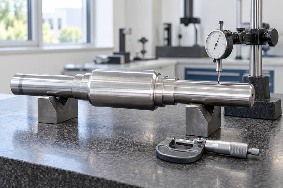
Open die forging produces shafts, sleeves, flanges, rings, and blocks, but dimensional accuracy depends on material, section size, geometry, and processing conditions. As-forged dimensions generally require different tolerances from finished machined surfaces.
Buyers need to distinguish forging tolerances, machining allowances, geometric requirements, and surface finish specifications. Each manufacturing stage requires dimensional controls, inspection methods, and acceptance criteria agreed before production.
What Accuracy Can Open Die Forging Achieve?
Open die forging accuracy depends on the component’s manufacturing stage. As-forged blanks, rough-machined components, and finish-machined parts have different dimensional requirements and inspection expectations.
In open die forging, repeated compression between open dies changes the workpiece geometry without completely enclosing it. Final dimensions therefore depend on deformation control, material behavior, and subsequent processing.
As-Forged Tolerances
As-forged tolerances define acceptable dimensional variation after forging and cooling, before machining. They commonly address outside diameters, overall lengths, section thicknesses, and basic geometric features.
Unlike closed-die production, open-die operations do not fully constrain the workpiece inside a shaped cavity. Material flow and successive reductions influence the resulting dimensions.
For example, a forged shaft may have different diameter variations along its length. Local deformation, workpiece rotation, and temperature differences can affect section uniformity.
Forging drawings should identify the allowable size variation for each relevant feature. An agreed tolerance cannot automatically be transferred between different materials, diameters, or component configurations.
Surface scale, local irregularities, and section transitions also influence inspection. Measurement locations must be specified carefully to avoid comparing unrelated surface conditions.
Rough-Machined Tolerances
Rough machining removes excess material and establishes more consistent surfaces for subsequent operations. It also helps identify whether sufficient stock remains for final machining.
For forged shafts, rough turning may establish reference diameters, reveal local surface defects, and prepare bearing or coupling regions for later finishing.
Rough-machined dimensions should retain the required finishing allowance. Their tolerances must account for subsequent heat treatment, expected distortion, and any planned machining operations.
A rough-machined shaft might satisfy its intermediate diameter tolerance while remaining unsuitable for final production if insufficient material remains around an eccentric section.
Inspection should therefore verify both intermediate dimensions and remaining stock. Checking the diameter alone does not establish whether final machining can achieve the drawing requirements.
Finish-Machined Tolerances
Finish machining produces the specified final dimensions and functional surfaces. Component geometry and required accuracy determine whether turning, boring, milling, or grinding is appropriate.
Critical features can require tighter control than nonfunctional surfaces. Bearing seats, sealing diameters, mounting faces, and accurately positioned bores are common examples.
However, precision machining does not mean the original forging achieved equivalent accuracy. The tolerance belongs to the finished feature and its specified manufacturing condition.
The achievable result depends on machine capability, fixturing, workpiece stability, material condition, and measurement methods. Requirements must be evaluated against the actual component.
| Delivery condition | Main dimensional objective | Typical inspection focus | Important limitation |
| As-forged | Produce the required blank geometry | Overall size, section dimensions, shape variation | Dimensions depend on forging and cooling conditions |
| Rough-machined | Establish workable surfaces and retain finishing stock | Intermediate dimensions, alignment, remaining allowance | Final tolerances are not yet established |
| Finish-machined | Meet specified functional drawing dimensions | Critical sizes, geometric controls, surface finish | Accuracy applies to machined features, not the original forging |
The appropriate tolerance must therefore be associated with a defined delivery condition. A quotation describing only a single accuracy value leaves important manufacturing responsibilities unclear.
What Factors Affect Open Die Forging Tolerances?
Forging tolerances depend on how the workpiece deforms, cools, and responds to subsequent operations. Understanding these influences helps engineers specify realistic manufacturing requirements.
Material, Size, and Geometry
Different materials have different hot-deformation characteristics, thermal expansion behavior, and cooling responses. These properties influence dimensional variation during and after forging.
When ordering forgings in different steel grades, buyers should not assume that the heating temperatures and deformation schedules approved for one grade will suit another. Similar component dimensions do not necessarily produce equivalent forging behavior across different materials.
Section size also matters. Large cross-sections may develop temperature differences between their surfaces and interiors, affecting deformation and cooling behavior.
Long shafts introduce straightness concerns, while hollow sleeves require attention to outside diameter, bore position, and wall thickness where those features exist.
Stepped components introduce additional challenges. Abrupt section changes can produce uneven material flow, making dimensional control more complicated than for uniform cylindrical blanks.
Forging sequence, workpiece rotation, reduction distribution, and reheating decisions affect the resulting shape. These operations must be considered together rather than independently.
A simple block may primarily require thickness, width, and flatness controls. A stepped shaft may additionally require shoulder locations, alignment, and sufficient stock at several diameters.
Heat Treatment and Machining Sequence
Heat treatment can change component dimensions through thermal expansion, phase transformations, stress redistribution, and uneven heating or cooling. The magnitude depends on material and geometry.
Quenching can introduce significant distortion in some configurations. Annealing, normalizing, and tempering also require consideration of temperature history and dimensional stability.
For long components, bending after heat treatment may affect machining setup. Hollow sections can experience dimensional changes that complicate subsequent bore finishing.
The manufacturing sequence consequently influences achievable accuracy. Rough machining before heat treatment may establish reference surfaces while retaining stock for correcting subsequent distortion.
Finish machining after the required heat treatment is often appropriate for dimensions sensitive to distortion. The correct sequence nevertheless depends on material condition and component requirements.
An intermediate inspection can identify bending, dimensional movement, or insufficient stock before final machining. Any straightening operation requires agreement on its applicability and acceptance conditions.
Final dimensional inspection must occur at the specified production stage. Measurements taken before a distortion-producing operation cannot establish compliance after that operation.
How Do Machining Allowance and Forging Tolerance Differ?
Machining allowance and forging tolerance describe different requirements. Confusing them can lead to undersized blanks, excessive material removal, or rejected finished components.
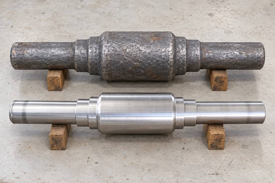
Forging tolerance defines the permissible variation from a specified forging dimension. Machining allowance represents material intentionally provided for removal during subsequent machining.
Allowance must accommodate dimensional variation, surface irregularities, alignment requirements, and the planned machining sequence. It is not itself a permissible dimensional deviation.
How Is Machining Allowance Calculated?
For a simple cylindrical blank, nominal radial machining allowance is calculated from the difference between forging and finished diameters.
Consider a clearly hypothetical shaft with an as-forged nominal outside diameter of 210 mm and a required finished diameter of 200 mm.
The nominal radial allowance is:
Nominal radial allowance = (210 − 200) ÷ 2 = 5 mm.
This gives 5 mm of material per side only when the forging is ideally round, centered, and exactly at its nominal diameter.
It is an illustrative calculation, not a tolerance capability, guaranteed machining allowance, or production specification offered by Boberry Machining.
Why Does the Lower Forging Limit Matter?
A nominal allowance calculation does not establish the minimum material available. The lower dimensional tolerance limit must also be evaluated.
For illustration, suppose the hypothetical 210 mm forging diameter has an agreed tolerance of ±3 mm. Its permitted lower diameter would then be 207 mm.
Under ideal concentric conditions, the nominal radial stock at that lower limit becomes:
Radial stock at the lower diameter limit = (207 − 200) ÷ 2 = 3.5 mm.
The ±3 mm value is hypothetical and does not represent a recommended or guaranteed open-die forging tolerance.
The calculated 3.5 mm assumes a round section with aligned centerlines. Actual material availability may be lower because of eccentricity, bending, or surface irregularities.
How Do Centerline Displacement and Surface Cleanup Affect Allowance?
A forging can meet its diameter requirement yet have insufficient machining stock on one side if its centerline differs from the intended machining axis.
In the same simplified example, a 2 mm centerline displacement could reduce the minimum radial stock from 3.5 mm to approximately 1.5 mm.
This calculation assumes ideal circular cross-sections and a fixed finishing axis. It excludes other geometric errors and does not establish an acceptable displacement.
Scale removal, surface depressions, and local imperfections can further reduce usable stock. Material must remain available wherever the final machined surface is required.
Straightening or changing the machining setup may improve material distribution, but those measures cannot be assumed feasible for every component.
For hollow components, inside and outside allowances must be evaluated together. Increasing the bore diameter removes material from the inner surface and affects final wall thickness.
For forged cylinder sleeves, bore position, outside diameter, and wall uniformity can therefore be equally important during machining planning.
A suitable allowance considers the worst relevant combination of permitted dimensions and geometric deviations, not merely the difference between two nominal diameters.
Which Dimensional and Geometric Tolerances Matter?
Dimensional and geometric tolerances control different characteristics. A component can satisfy its measured size limits while failing straightness, roundness, or alignment requirements.
The engineering drawing must distinguish each requirement and identify which features are functionally important. This prevents unnecessary machining while protecting critical assembly conditions.
Dimensional Requirements
Dimensional tolerances establish permissible variations in measurable sizes and distances. Common examples include shaft diameters, sleeve lengths, block thicknesses, and flange dimensions.
For stepped shafts, shoulder-to-shoulder distances may control the relative positions of bearings or couplings. Overall length alone cannot verify these relationships.
For sleeves, inside and outside diameters influence assembly fits and wall thickness. Both dimensions require suitable tolerances where they affect component function.
An acceptable overall diameter does not necessarily establish acceptable wall thickness. Eccentricity between the inner and outer surfaces can produce uneven material distribution.
Dimensions should also specify their manufacturing stage. An as-forged outside diameter and a finished bearing diameter cannot reasonably share acceptance criteria without further evaluation.
Geometric Requirements
Geometric tolerances describe permitted variation in form, orientation, or location. They address characteristics that size measurements alone cannot adequately control.
Common requirements include straightness, flatness, roundness, cylindricity, perpendicularity, and coaxial relationships between cylindrical features.
A shaft may have acceptable diameters at several measured locations but still exhibit excessive bending. Straightness inspection evaluates that condition separately.
Similarly, a flange may meet its thickness requirement while its mounting face exceeds the permitted flatness deviation, preventing acceptable contact during assembly.
Roundness controls the form of individual circular sections. Cylindricity addresses the overall cylindrical surface, including relevant form variation along its length.
Coaxial requirements evaluate relationships between cylindrical features. Their inspection must use the datum references and tolerance definitions specified on the approved drawing.
A designated feature or combination of features establishes the theoretically exact reference known as a datum. It provides the basis for relevant measurements and geometric controls.
For a machined shaft, an agreed datum axis may be established from specified center features or cylindrical surfaces. Its definition must match the intended inspection setup.
An unfinished forging may not have suitable precision datum features. Temporary reference surfaces or an agreed alignment procedure may be necessary for intermediate measurements.
Measurement Temperature and Inspection Conditions
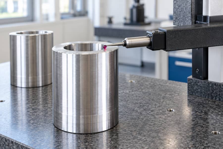
Metal dimensions change with temperature. Measurements taken on a warm forging may differ from measurements taken after the component reaches a stable inspection temperature.
A reference temperature of 20°C is commonly used for dimensional metrology, but the applicable measurement temperature and any correction requirements must be agreed.
Large components also require consideration of temperature gradients. Surface temperature alone may not represent the thermal condition of the entire workpiece.
Inspection procedures should identify measurement equipment, contact locations, supporting conditions, and datum setup. Long shafts can deflect under their own weight during inspection.
Surface finish is another separate requirement. Roughness values describe surface texture and cannot substitute for dimensional or geometric tolerance verification.
| Requirement | What it controls | Example inspection consideration |
| Size tolerance | Permitted diameter, length, or thickness variation | Measure at agreed positions |
| Straightness | Deviation of a line or axis from straightness | Define supports and evaluation method |
| Roundness | Circular form of a cross-section | Check specified sections |
| Flatness | Form of a surface relative to an ideal plane | Establish measurement coverage |
| Perpendicularity | Orientation relative to a datum | Use the agreed datum reference |
| Coaxial relationship | Relative alignment of cylindrical features | Establish datum axis and measurement procedure |
| Surface roughness | Fine-scale surface texture | Specify roughness parameter and assessment method |
These requirements must be evaluated independently unless the drawing explicitly establishes a combined control. Passing one measurement does not demonstrate compliance with every related feature.
How Should Buyers Specify Open Die Forging Tolerances in an RFQ?
A useful request for quotation identifies the required delivery condition, functional features, manufacturing constraints, and inspection responsibilities. Clear specifications reduce disagreement during production acceptance.
Drawing and Inspection Requirements
Start with a complete engineering drawing showing nominal dimensions, applicable tolerances, material requirements, and geometric controls. Provide a revision identifier to prevent specification conflicts.
For forged blanks, separate the forging dimensions from the intended final-machined geometry. This allows the required machining stock to be evaluated correctly.
If rough machining is included, identify intermediate dimensions and remaining allowances. Specify which surfaces must be prepared for inspection or later manufacturing operations.
Critical machined surfaces should have independently defined tolerances. Avoid applying the tightest dimension requirement to every feature when only selected locations require precision.
The RFQ should also identify the heat-treatment condition at delivery. Dimensions inspected before heat treatment may not remain unchanged afterward.
Where applicable, agree on the governing drawing standard, specified datums, inspection temperature, measurement equipment, and reporting format.
Practical RFQ Checklist
Include the following information when requesting custom open-die forgings:
- Component identification: Part name, drawing number, revision, quantity, and intended delivery condition.
- Material specification: Material grade, applicable standard, and required material condition.
- Forging geometry: Overall dimensions, section transitions, minimum sections, and relevant as-forged tolerances.
- Machining allowance: Required stock on each critical surface, including lower-limit and alignment considerations.
- Machining scope: As-forged delivery, rough machining, finish machining, or a combination.
- Dimensional tolerances: Critical diameters, lengths, wall thicknesses, and shoulder positions.
- Geometric tolerances: Straightness, flatness, roundness, perpendicularity, and relevant alignment controls.
- Datum requirements: Reference features, datum establishment methods, and inspection setup.
- Heat-treatment requirements: Specified condition, manufacturing sequence, and post-treatment checks.
- Inspection requirements: Measurement temperature, inspection stages, acceptance criteria, and required records.
- Surface requirements: Applicable surface finish, cleanup expectations, and permissible surface conditions.
These details help establish which operations are included in the quotation and which dimensional requirements remain the buyer’s or subsequent machining supplier’s responsibility.
Example of Dimensional Acceptance Requirements
Consider a hypothetical stepped shaft purchased as a rough-machined forging. The engineering drawing identifies two bearing regions requiring finish machining after heat treatment.
The RFQ should define intermediate diameters, minimum remaining machining stock, the intended datum axis, and the permissible geometric deviations before final machining.
Acceptance at the rough-machined stage would verify those intermediate requirements. It would not imply that the finished bearing dimensions had already been achieved.
If final machining is included, the inspection plan should additionally verify finished diameters, alignment, relevant surface roughness, and other drawing-defined characteristics.
A dimensional report should identify the measured features, actual results, inspection condition, and acceptance limits. Any nonconforming results require documented disposition.
Boberry Machining’s Custom Forging Requirements
Boberry Machining supplies custom open-die forgings, including shafts, sleeves, flanges, rings, and blocks, with machining, heat treatment, and inspection arranged according to agreed order requirements.
For each component, the required manufacturing condition and dimensional expectations should be established through drawing review before production commitments are finalized.
Forging geometry, machining allowances, heat-treatment sequence, and inspection requirements must be assessed together because each can influence subsequent dimensional acceptance.
As-forged tolerances should remain distinguishable from finish-machined tolerances throughout quotation, production, and inspection. No universal accuracy figure can replace the approved component specification.
A complete RFQ enables Boberry Machining to review the requested manufacturing scope and determine which dimensional requirements, inspection stages, and acceptance records can be agreed for the order.