
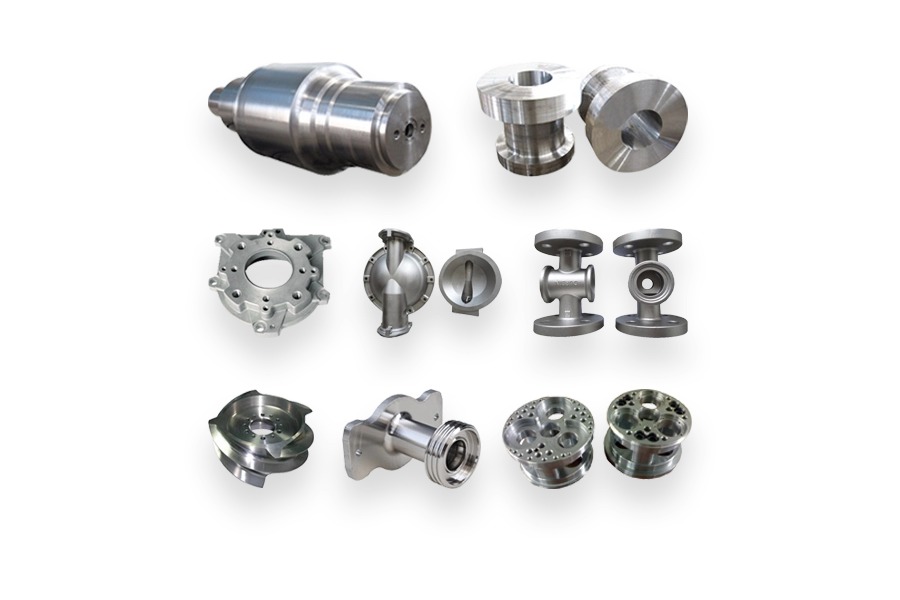
Mechanical parts are the individual components that carry loads, transmit motion, connect equipment, or contain fluids within a machine or industrial system. They include flanges, pipe fittings, shafts, gears, sleeves, hubs, discs, rings, and custom cast bodies. Some remain stationary throughout operation; others rotate, slide, or transfer force on every operating cycle. Understanding what each part does is the starting point for choosing its material, manufacturing route, dimensions, and inspection requirements.
Forging shapes solid metal through compressive force, whereas metal casting forms a component by allowing molten metal to solidify in a mold. A forged or cast blank may still require thermal processing and the removal of stock from its functional surfaces. Neither replaces the need to verify the finished component against its intended duty.
| Part family | Principal function | Typical specification focus |
| Flanges | Connect or close equipment and piping interfaces | Standard, facing, rating, and mating geometry |
| Pipe fittings | Join, branch, redirect, or terminate a fluid path | Material, connection, wall section, and service conditions |
| Shafts | Support rotating components and transmit motion | Loads, journal fits, runout, and heat treatment |
| Gears and hubs | Transfer torque through a drive assembly | Tooth geometry, bore interface, and alignment |
| Sleeves | Provide a bore, guide, or replaceable contact surface | Bore geometry, wall thickness, and mating fit |
| Discs and rings | Provide circular blanks or structural components | Material condition, section geometry, and machining allowance |
| Custom cast components | Combine structural features and internal passages | Castability, functional surfaces, and acceptance criteria |
Metal Flanges: Connecting Pipes, Valves, and Equipment
A flange provides a connection face that can be fastened to another component. In process piping, a typical flanged joint brings together two compatible flanges, a gasket, and bolting. The flange supplies the supporting geometry; successful sealing depends on the complete joint, including alignment, gasket selection, assembly procedure, and operating conditions.
Common designs and their functions
Weld neck flanges connect to pipe through a butt weld. Slip-on flanges fit over the pipe and are attached using the specified weld arrangement. Blind flanges close an opening, while lap joint arrangements use a separate backing flange with a stub end. Swivel designs provide rotational adjustment for bolt alignment. These names describe construction features, not interchangeable performance levels.
Industrial uses include pump connections, process lines, pressure equipment interfaces, and maintenance access points. For a replacement flange, matching the outside diameter alone is insufficient. The bolt pattern, facing, bore, thickness, material specification, and applicable rating must also be compatible with the adjoining equipment.
What to confirm before ordering
- Interface: Specify the standard, nominal size, flange type, facing, and mating component.
- Service: Provide the design pressure, design temperature, fluid, and relevant piping specification.
- Documentation: State the required material certification, marking, dimensional inspection, and any additional testing.
A pressure class is not a universal pressure value in psi. Material and temperature affect allowable service conditions, so selection should use the applicable standard tables rather than a generic catalogue shortcut. ASME describes the pressure-temperature, material, and dimensional scope of its flange standards in its B16 standards overview.
For a closer comparison of connection designs, read Boberry’s weld neck, slip-on, and swivel flange guide.
Cast Pipe Fittings: Building the Fluid Path
Pipe fittings organize the route through which a fluid moves. Fitting geometry determines the route through the assembly: elbows turn the flow path, tees divide it, reducers transition between pipe sizes, and caps terminate an unused opening. Couplings and unions connect sections with different assembly and maintenance arrangements. A fitting therefore needs to suit both the flow path and the way the system will be installed.
Cast pipe fittings are one manufacturing category within the broader metal fittings family. Other fittings may be forged, formed from pipe, or machined from stock. The shape of an elbow or tee does not prove how it was made. Purchasing documents should identify the required manufacturing and material specifications when those distinctions affect acceptance.
Applications and connection requirements
Examples include cooling-water networks, chemical transfer lines, treatment equipment, compressed-air distribution, and marine auxiliary systems. Selection begins with the fluid and operating conditions, then moves to connection geometry, wall requirements, corrosion exposure, and maintenance access. A threaded connection, for example, must match the specified thread system rather than simply having a similar nominal diameter.
For cast pressure-containing components, buyers should agree on inspection coverage, acceptance criteria, and pressure or leak testing where required. Review material traceability separately from pressure-boundary integrity, and request the evidence specified for each characteristic.
Consider installation access as well. A fitting that fits a drawing may leave insufficient room for welding, tightening, inspection, or later removal. Resolve these issues with the assembly layout before approving a production order. For more detailed selection questions, see how to select pipe fittings for an industrial system.
Forged Shafts: Supporting Rotation and Transmitting Motion
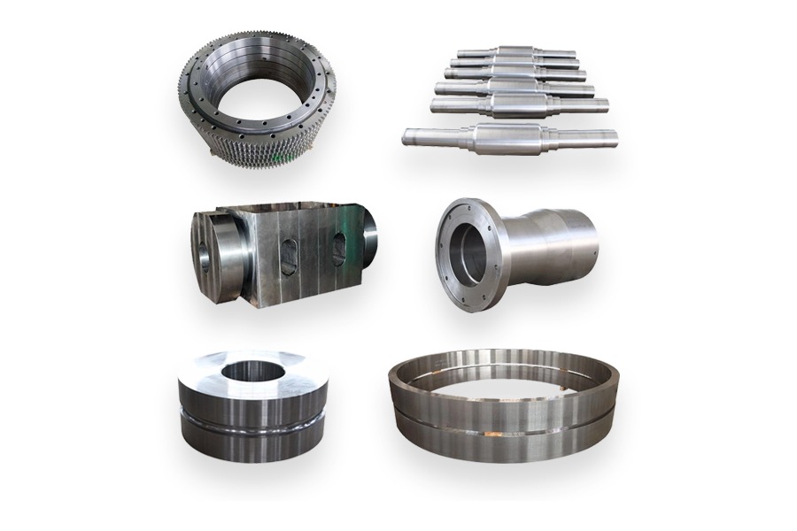
A shaft provides an axis around which other components operate. Depending on the assembly, it may carry gears, bearings, pulleys, impellers, or couplings while transmitting torque. Its performance depends on the combined action of loading, geometry, material condition, bearing support, and surface quality.
Step shafts, eccentric shafts, and crankshafts
A step shaft uses changes in diameter to locate components along a common axis. An eccentric shaft contains an offset feature that creates controlled motion as it turns. A crankshaft uses crank throws to link rotary and reciprocating movement. These geometries serve different motion requirements and should not be selected simply by their overall size.
Forged shafts are used in industrial drives, presses, pumps, compressors, and heavy machinery when the design calls for a forged starting form. Forging can help develop favorable material flow, but the finished shaft still needs appropriate heat treatment, machining, and inspection. A statement that a shaft is forged is not itself a fatigue qualification.
Practical specification points
The drawing should distinguish bearing seats, seal tracks, coupling seats, and noncritical surfaces. Specify the dimensions and geometric relationships needed for assembly, including datum references and runout where relevant. A very tight diameter tolerance does not automatically control straightness or the relationship between separated journals.
For a replacement shaft, provide the original drawing revision and service history when available. Photographs and an old sample can help establish geometry, but wear may have altered the measured dimensions. Confirm which features represent the intended design before using the sample as manufacturing authority.
Boberry’s step shaft, eccentric shaft, and crankshaft comparison explores these design families in more detail.
Forged Gears and Gear Blanks: Controlling Speed and Torque
Gears transfer motion through meshing teeth. Their geometry determines the relationship between the driving and driven members, while material condition, lubrication, alignment, and tooth accuracy influence how the transmission performs under load. A gear blank is the starting component from which the finished tooth geometry may later be produced.
Choosing the gear arrangement
Spur gears are commonly used between parallel shafts. Parallel-axis helical gears have angled teeth, and bevel gears serve intersecting shaft arrangements. The selection also affects the surrounding assembly. For example, a single-helical gear mesh develops axial thrust that the support arrangement must accommodate.
Typical industrial settings include gearboxes, conveyor drives, lifting machinery, and processing equipment. A gear should be considered together with its mating gear and supports. Replacing only one element without checking the contact pattern, lubrication condition, and alignment can leave the underlying operating problem unresolved.
Specify the delivery condition
Before requesting quotations, establish whether the order covers a forged blank, a rough-machined blank, or a finished gear. Identify responsibility for tooth cutting, heat treatment, finishing, and inspection. Calling both offers a gear quotation can conceal whether the supplier has included tooth cutting, thermal treatment, and final verification.
A useful enquiry includes the gear drawing, material and treatment requirements, bore details, tooth data, quantity, and inspection expectations. Where the supplier is expected to review suitability, provide speed, loading, duty cycle, and operating environment rather than asking for a general-purpose recommendation.
For the main geometry choices, continue to spur, helical, and bevel gear differences.
Forged Cylinder Sleeves: Providing Controlled Bores and Contact Surfaces
Sleeves are cylindrical components used to create a defined bore, support a mating part, or provide a replaceable contact surface. The term covers several distinct applications. An engine liner, a bearing sleeve, and a custom pressure-equipment sleeve may look similar externally while requiring very different materials, finishes, and inspection methods.
Match the sleeve to its actual duty
Custom forged sleeves may have through bores, blind bores, shoulders, or integral flanges. Each feature changes the machining and assembly questions. For a blind bore, tool access and inspection reach must be considered. For a flanged sleeve, the relationship between the bore and seating face may be as important as the bore diameter.
Applications can include machinery guides, hydraulic equipment, replaceable wear locations, and specialized cylindrical assemblies. Do not infer pressure suitability or sliding performance from the word sleeve. State the actual duty, including whether the part contains pressure, guides motion, or supports a stationary interface.
Control geometry after processing
Specify bore diameter, relevant form tolerances, surface finish, wall requirements, and the mating fit. Identify whether dimensions apply before or after heat treatment and final machining. Where assembly can change the bore shape, agree on the condition in which the final measurement will be made.
Keep the reference sample linked to its drawing revision and documented measurement procedure when arranging subsequent production batches. A previously accepted part is useful for comparison, but a controlled specification prevents gradual changes in fit from passing unnoticed between production batches.
Read the guide to tolerances in forged cylinder sleeve manufacturing for a closer discussion of dimensional requirements.
Forged Hubs: Connecting Shafts to Driven Components
A hub forms the central connection between a shaft and a component such as a gear, wheel, pulley, or coupling. It must transfer the required torque while maintaining the intended position and alignment. The connection can use a key, spline, clamping arrangement, interference fit, or another engineered interface.
Connection design and maintenance
A keyed hub uses a localized feature to transmit torque. Splines distribute the connection across multiple teeth, while clamping designs depend on the specified contact and tightening arrangement. Their suitability depends on more than nominal torque: load reversals, shaft condition, assembly access, and planned disassembly all matter.
In conveyor drives, mixing equipment, and other rotating assemblies, a hub may be replaced more frequently than the shaft. The connection should therefore support the required maintenance method. A design intended for permanent assembly can create unnecessary difficulty where frequent removal is part of normal operation.
Questions for a custom hub enquiry
Provide the mating shaft dimensions and connection details rather than a hub drawing in isolation. Establish how axial movement is restrained, how the hub is located during machining, and which surface is used as the inspection datum. These details help prevent a part from passing individual dimensional checks while failing to align correctly in the machine.
For a weld-on design, clarify the material and welding requirements before production. Welding can change the final geometry, so the manufacturing plan should identify which critical features are checked or finished after welding. For the principal torque-transfer options, see keyed, spline, and clamp hub designs.
Forged Discs: Circular Starting Forms for Custom Components
A forged disc is a circular solid or near-solid form that can be supplied as a blank or machined into a finished component. Depending on the drawing, it may become a cover, mounting element, rotor component, tube sheet, or another engineered part. The intended function, rather than the disc shape alone, determines its requirements.
Blank dimensions versus finished dimensions
The enquiry should show whether quoted dimensions describe the forging envelope or the finished component. Allowance for facing, turning, drilling, and other machining must be agreed explicitly. Excess stock adds handling and machining work, while insufficient stock can prevent the finished surfaces from cleaning up correctly.
For discs with extensive drilling, discuss the hole pattern, datum scheme, remaining sections, and manufacturing sequence. For rotating applications, state the required checks relating to the rotation axis and any balancing requirement. A stationary cover and a rotating disc should not share an inspection plan merely because their envelopes are similar.
Choosing a suitable starting route
A forged disc, a casting, and a plate-cut blank can each be appropriate in different designs. The choice should consider material specification, loading, section geometry, inspection access, quantity, and downstream machining. Avoid selecting a route solely because it produces the lowest blank price.
Request the same delivery condition from competing suppliers so the comparison is meaningful. Include material treatment, machining scope, inspection records, and surface protection in the enquiry. Boberry’s forging, casting, and machining comparison provides a broader starting point for reviewing manufacturing routes.
Seamless Rolled Rings: Annular Components for Industrial Assemblies
Seamless rolled rings begin with a pierced or hollow workpiece that is expanded and shaped between rolls. This produces a continuous ring without a circumferential welded joint. The Forging Industry Association’s process overview describes this ring-rolling method alongside other forging operations.
Depending on the design and subsequent processing, rolled rings can become bearing-ring blanks, gear-ring blanks, flanges, or structural rings. These are possible manufacturing applications rather than guarantees that any ring blank is ready for service. Final machining, heat treatment, and inspection remain part of the product definition.
What the ring drawing should establish
Key information includes inside diameter, outside diameter, axial height, section profile, material condition, and machining allowance. Where the ring supports a bearing or seal, identify the functional surfaces and their relationships. A nominal overall diameter gives too little information to determine whether the ring can meet the finished assembly requirements.
For large rings, discuss lifting, support, transportation, and the measurement setup. Inspection should be repeatable and reflect the agreed drawing requirements. Specify the delivery state clearly, particularly if the buyer will perform final machining or heat treatment after receipt.
Material selection should follow loading and environment. Corrosion resistance, required mechanical properties, weight, and treatment capability can lead to different alloy choices. For a comparison of material families, read stainless steel, carbon steel, and aluminum rolled ring forgings.
Custom Cast Components: Combining Shape, Structure, and Internal Passages
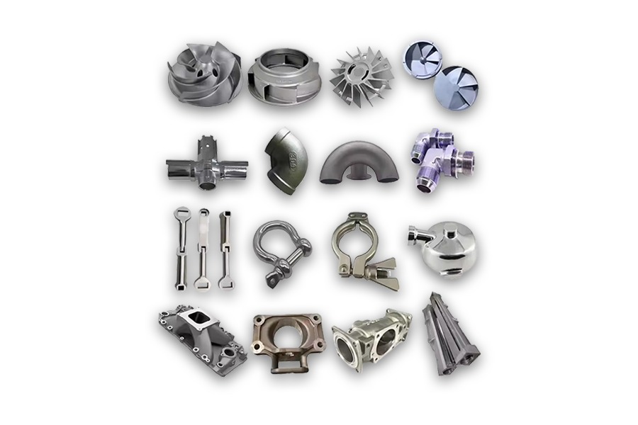
Custom cast components extend beyond pipe fittings to housings, brackets, valve bodies, covers, and other shapes designed around equipment requirements. Casting can incorporate ribs, bosses, recesses, and passages into the starting form, followed by machining where the assembly needs more closely controlled features.
Material families and functional surfaces
Boberry’s product categories include carbon steel, alloy steel, stainless steel, duplex stainless steel, and aluminum castings. These categories are useful for organizing enquiries, but the purchase order should identify a specific material specification and delivery condition. A broad description such as stainless steel does not define the required chemistry, mechanical properties, or suitability for a particular environment.
Separate functional interfaces from surfaces that do not contact other parts. Bearing locations, seal seats, mounting pads, and threaded connections may need machining, while other areas can remain in an agreed cast condition.
Move from product type to an orderable specification
Before placing an order for any of these mechanical parts, prepare a controlled package that explains both the component and the delivery scope. Include:
- Design documents: The drawing revision, model where available, datum system, and critical dimensions.
- Material requirements: The grade, governing specification, treatment condition, and required certificates.
- Manufacturing scope: Whether delivery is as-cast, as-forged, rough-machined, or fully finished.
- Verification plan: State which features require measurement, where testing applies, what records must accompany delivery, and how the initial production sample will be approved.
- Delivery details: Quantity, identification, protective packaging, and agreed delivery schedule.