
Application requirements shape a forged cylinder sleeve by determining what the bore must do, how loads enter the component, how it is retained, and which surfaces must remain accurate after installation. Two sleeves with the same outside diameter and length can require different materials, bore finishes, wall sections, and inspection methods. The correct starting point is the sleeve’s duty within the assembly, followed by a drawing that translates that duty into measurable requirements.
A sleeve may guide a moving member, contain fluid, protect a shaft, support a stationary interface, or provide a replaceable wear surface. Some designs combine several of these functions. Treating every cylindrical component as an engine liner can therefore lead to unsuitable assumptions about lubrication, cooling, sealing, and material selection.
Define the Sleeve’s Function Before Selecting Its Geometry
Identify what happens inside and outside the sleeve
Start with the relationships between the sleeve and its neighboring components. Is a piston moving through the bore? Is a shaft rotating against an internal surface? Does the outside diameter seat tightly inside a housing? Does the component form part of a pressure boundary? These questions establish the functional surfaces.
Describe the operating cycle as well as the normal condition. Starting, stopping, reversing, thermal cycling, and occasional overloads can matter even when average loads appear modest. If the design already exists, provide the relevant operating information as context without replacing the controlled drawing with a general description.
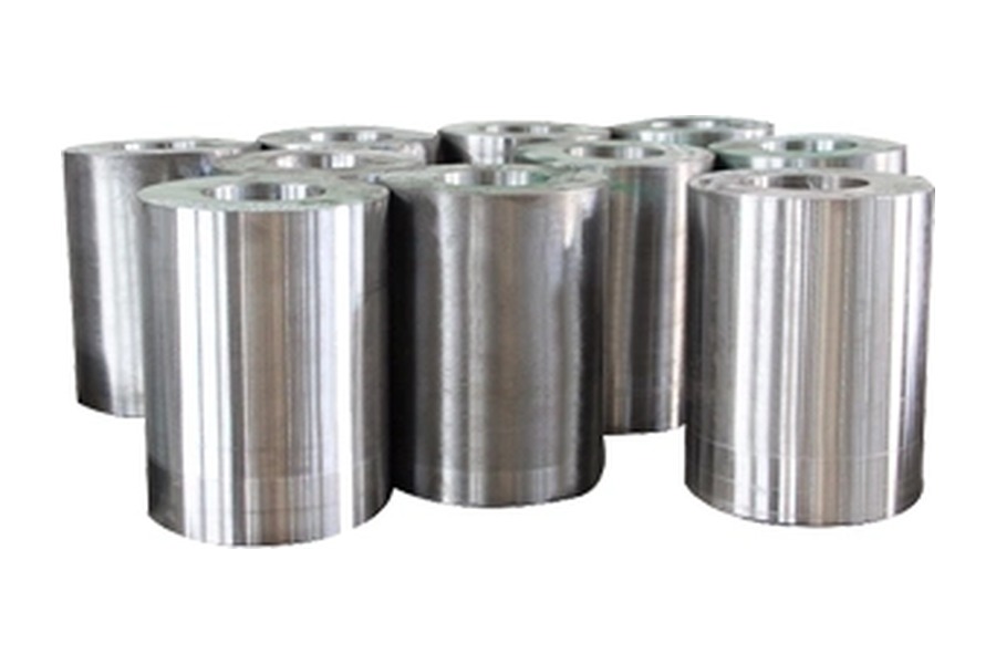
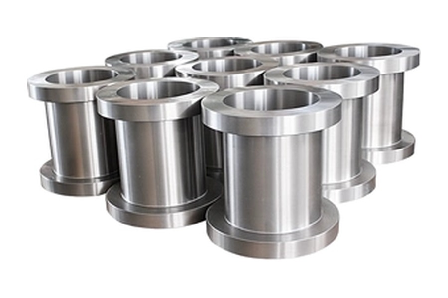
Boberry’s custom forged cylinder sleeves include different structural forms. The appropriate form depends on the actual duty and manufacturing plan, rather than the visual similarity between two products.
Distinguish a sleeve from the complete cylinder assembly
A sleeve is one component within a larger system. Seals, supporting structures, fasteners, end closures, and mating surfaces may determine whether the assembly performs as intended. The sleeve supplier cannot establish all of those relationships from outside dimensions alone.
For pressure-containing applications, provide the governing design requirements and approved component specification. A forged manufacturing route does not itself assign a pressure rating. Similarly, the word sleeve does not establish a permissible load, operating temperature, or expected service life.
| Primary duty | Design focus | Information needed from the buyer |
| Linear guidance | Bore alignment, contact length, and mating clearance | Motion, support layout, and side loading |
| Fluid containment | Pressure boundary, closures, and sealing interfaces | Design conditions and applicable requirements |
| Replaceable wear surface | Contact material, finish, and removal access | Wear mechanism and maintenance method |
| Stationary support | Load transfer and locating surfaces | Assembly forces and surrounding stiffness |
| Thermally cycled service | Expansion, fit changes, and temperature gradients | Temperature range and cycle description |
Translate Loads and Pressure into the Sleeve Structure
Wall sections should follow the load path
The wall must support the specified duty after all machining is complete. A generous starting thickness is not evidence that the finished component is adequate. Bores, grooves, ports, threads, and reliefs can reduce the remaining section at important locations.
Identify where loads enter and leave the sleeve. A shoulder may carry axial force, while a seated outside diameter transfers radial loading into a housing. Local contact can behave differently from a load distributed over the full length. These relationships should guide both structural assessment and the drawing.
Avoid changing wall thickness only to simplify forging without reviewing the final assembly. Manufacturing feedback is useful, but any change that affects functional geometry should return to the responsible designer for approval.
Open bores and blind bores create different questions
A through bore allows access from both ends, which can simplify machining, cleaning, and measurement. A blind bore has an internal end surface that may be functionally important and more difficult to reach.
In a blind design, define the usable depth, bottom geometry, and transition between the cylindrical wall and end. Tool clearance, chip removal, and inspection reach must be considered. A drawing that specifies only overall depth may leave uncertainty about the length over which the full bore requirements apply.
Where the closed end carries pressure or mechanical load, its thickness and transition geometry belong to the engineering design. Do not treat that end as a leftover consequence of the machining operation.
Flanges and shoulders need defined contact conditions
A flange can provide axial location or a bolted connection, while an internal or external shoulder can establish an assembly stop. Their purpose determines which face must contact the mating component and which clearances must remain.
Specify the relationship between the locating face and bore axis when alignment matters. Also describe whether bolts clamp the sleeve directly or retain a separate support. Uneven support can affect the installed geometry even if the free component meets its drawing.
Design the Bore Around Motion, Lubrication, and Sealing
A working bore requires more than a diameter
Bore diameter is only one characteristic. Roundness, straightness, cylindricity, taper, surface texture, and alignment may also influence performance. The drawing should identify the characteristics relevant to the application instead of placing an extremely tight size tolerance on every surface.
A sliding component may need a bore finish compatible with its lubrication and contact arrangement. A stationary fit may have a different finish requirement. Where the bore supports a sealing element, use the requirements established for that sealing system.
The general concept of surface roughness helps explain why surfaces with similar dimensions can behave differently. However, one roughness number may not fully define a functional bore. State any additional texture requirements when the design depends on them.
Ports, grooves, and transitions affect usable surfaces
A port opening can interrupt a running surface or create an edge that a seal crosses during travel. Define the required edge treatment and make clear which regions are part of the working stroke.
Grooves should be located from functional references. Their depth, width, corner geometry, and relationship to the bore may matter independently. A general instruction to deburr does not necessarily establish the contour needed to protect a passing seal.
Specify whether internal intersections must be inspected visually, with a suitable instrument, or by another agreed method. Access limitations should be discussed before manufacture, particularly where the final assembly makes the feature inaccessible.
Cleanliness belongs in the delivery specification
Residue from machining, abrasive finishing, preservation, or packaging can enter a fluid system during assembly. The order should describe bore cleanliness at dispatch, suitable end covers, and protection until assembly.
Any cleanliness requirement needs an agreed verification approach. A statement that the sleeve is clean may be adequate for some general machinery, while other applications require documented limits and procedures. Match the requirement to the system instead of borrowing a specification without understanding its purpose.
Also identify preservatives that must be removed before installation. Compatibility with seals, working fluids, and subsequent processing should be checked by the parties responsible for those interfaces.
Match the Mounting Method to Installed Geometry
Interference fits change the boundary conditions
A sleeve installed with an interference fit is supported and constrained differently from a free component. Installation can change the bore geometry, especially where the sleeve or housing is relatively compliant.
State whether final bore requirements apply before installation, after installation, or under a defined inspection fixture. If the buyer intends to finish the bore after assembly, identify the stock and condition required at delivery.
Provide relevant housing information where the supplier is expected to review the fit. The sleeve outside diameter cannot be evaluated in isolation from the mating bore, temperature conditions, and assembly procedure.
Clearance fits need positive location and retention
A sleeve that slides into place may need a flange, shoulder, retaining feature, or other arrangement to control movement. Define what prevents rotation, axial displacement, or loss of alignment during service.
Clearance can facilitate maintenance, but it may also change support and contact conditions. Establish where the sleeve is intentionally supported and where a gap is required. A part that is easy to assemble may still perform poorly if its locating scheme is incomplete.
For bolted designs, coordinate fastener access, contact faces, and assembly sequence. These details affect whether the specified installation can actually be achieved inside the equipment.
Removal access should be designed in
Replaceable sleeves should have an agreed removal method. Consider whether tools can reach the component, whether adjacent parts must be removed, and whether extraction forces could damage a reusable housing.
Any extraction groove, threaded feature, or lifting provision must be part of the approved design. Adding a convenient hole during manufacture can create an unintended stress concentration or interrupt a sealing surface. Maintenance features deserve the same control as other functional geometry.
Select Material and Treatment for the Actual Contact Conditions
Evaluate the mating system
Material selection should consider the opposing surface, lubrication, environment, and required properties. A harder sleeve is not automatically the best solution if the mating component, contact mechanism, or corrosion conditions call for a different balance.
Put the exact grade designation and required metallurgical condition on the sleeve drawing. If corrosion resistance is important, communicate the medium and temperature conditions to the responsible engineering team. If wear dominates, explain the expected mechanism and whether contamination or dry operation occurs.
A forged steel sleeve should not be assumed interchangeable with a cast engine liner. Manufacturing route and material selection must follow the intended design and qualification requirements.
Coordinate treatment with the machining sequence
Heat treatment or surface treatment can affect dimensions, surface condition, and the stock required for finishing. Identify when each critical feature reaches its final state.
If the bore requires a treated surface, establish the relevant condition after final machining. Excessive stock removal after surface treatment can cut through the layer intended to provide wear resistance. Conversely, leaving the bore unfinished after treatment may fail the geometry or texture requirements.
Agree which surfaces are treated and which are protected. This is particularly important when the component combines a wear surface, a fitted outside diameter, and threaded or sealing features.
Avoid unsupported service-life promises
Forging is a manufacturing route, not a complete performance qualification. Service life depends on material, design, process control, assembly, and operating conditions. An enquiry should define the evidence needed for the application rather than asking the supplier to guarantee an undefined lifetime.
Where a replacement addresses a previous failure, include the observed damage and operating history. Distinguish confirmed observations from suspected causes so the redesign review begins with reliable information.
Plan Manufacturing and Inspection Around the Critical Features
Establish references that survive the production route
A sleeve may be forged, rough-machined, treated, and finished in several setups. The manufacturing plan should preserve suitable references so the bore, outside diameter, and locating faces can be produced in the intended relationship.
Identify whether temporary workholding features are allowed and when they are removed. For long or thin sections, discuss how support and clamping influence the geometry measured during production.
Boberry’s article on tolerances in forged cylinder sleeve manufacturing provides further context for dimensional requirements. The present specification should still define the individual characteristics that matter in the buyer’s assembly.
State the measurement condition
A useful inspection plan explains more than which instrument will be used. It identifies the reference surfaces, component support, measurement locations, and any required temperature condition.
For the bore, specify where readings are taken if variation along the length matters. A measurement at the entrance alone cannot describe an inaccessible region near a blind end. Agree the method before manufacture where instrument access is difficult.
For features influenced by installation, determine whether a free-state measurement is sufficient. If a fixture or assembled inspection is required, establish who supplies it and how its condition is controlled.
Separate dimensional and material evidence
Dimensional conformity, material certification, hardness checks, and specified integrity examination answer different questions. Request the records needed for each without treating one document as a substitute for all the others.
First-article review should confirm the agreed characteristics and resolve unclear drawing notes before repeat production. If a proposed deviation affects a running or sealing surface, obtain the relevant engineering decision rather than accepting it solely because assembly remains possible.
Turn the Application into a Complete Sleeve Enquiry
Prepare the enquiry around the sleeve’s function and delivery state. Include the controlled drawing, available model, material requirement, and the information needed to understand its interfaces.
- Operating duty: Explain motion, loading, fluid exposure, and relevant temperature changes.
- Mating parts: Provide the interfaces that determine fit, support, and sealing.
- Manufacturing condition: Identify whether the order covers a blank, a partly machined sleeve, or a finished component.
- Functional surfaces: Mark the bore regions, locating faces, and other critical features.
- Verification: Define inspection coverage, documentation, and any first-article hold point.
- Installation scope: State whether final finishing or measurement occurs after assembly.
- Delivery protection: Specify preservation, opening protection, identification, and handling needs.
Before approving the order, review the drawing with the parties responsible for manufacture and assembly. Resolve whether dimensions apply before or after treatment, whether the bore is accepted free or installed, and who completes any remaining operations.
The wider Mechanical Parts Guide places sleeves alongside shafts, hubs, flanges, and other components. For an individual sleeve, the most useful specification follows its actual function: what it contacts, what it contains, how it moves, and how it is supported. Those answers turn a simple cylindrical outline into a component that can be manufactured and checked against clear requirements.