
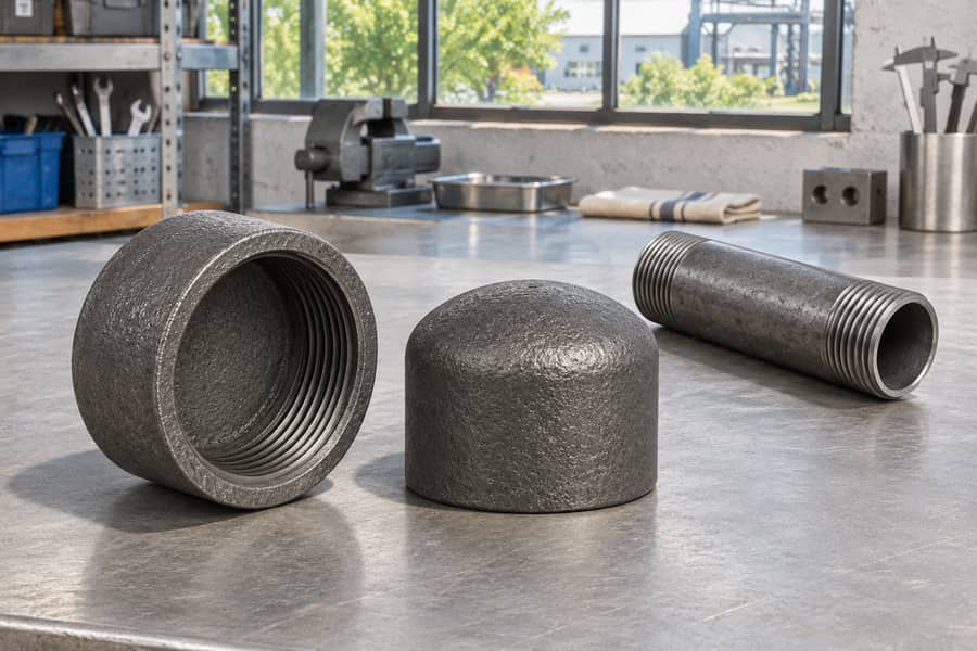
Cast iron pipe caps close pipeline ends, but suitability depends on material grade, end geometry, connection details, and service conditions. Nominal pipe size alone cannot establish structural suitability.
Engineers must define loading, sealing, restraint, and verification together. Gray iron intended for non-pressurized drainage or venting must not be assumed suitable for pressure service without specific qualification.
Understanding Cast Iron Pipe Caps and Their Design Functions
What Is a Cast Iron Pipe Cap?
A cast iron pipe cap is an end-closure fitting designed to cover an open pipe termination. Its primary function is to prevent the conveyed medium from escaping while providing a mechanically compatible connection to the pipeline.
Unlike components that redirect or divide flow, a pipe cap creates a closed boundary. Its geometry must therefore accommodate the loads generated at the termination, particularly when internal pressure or external mechanical forces are present.
The cap body, connection interface, and sealing arrangement work together. A suitable design must maintain dimensional compatibility while transferring applicable loads into the pipe and its supporting or restraint system.
Cast iron caps may be considered for drainage, ventilation, and other industrial applications, depending on material specifications and product qualification. Their suitability cannot be determined from appearance or nominal diameter alone.
Pipe Caps vs. Plugs and Blind Flanges
Pipe caps, plugs, and blind flanges all close pipeline openings, but their connection geometries and load-transfer arrangements differ. Understanding these distinctions prevents incorrect component selection during pipeline design and procurement.
A female-threaded pipe cap fits over the externally threaded end of a pipe. Its internal threads engage the pipe threads, while the cap body extends around the termination to create the closed end.
A plug instead carries its thread on the outside and screws into a female opening. Its external threads enter a female-threaded opening, such as a threaded port or fitting. A plug therefore closes an opening rather than covering the outside of a pipe end.
A bolted blind flange uses a different arrangement. It attaches to a mating flange through bolts and normally relies on a gasket positioned between the corresponding flange faces to establish the seal.
These configurations have different requirements for engagement, sealing, alignment, and mechanical restraint. Engineers should specify the actual connection arrangement instead of using the terms cap, plug, and blind flange interchangeably.
Material Selection for Cast Iron Pipe Caps
Gray Cast Iron: Characteristics and Application Limitations
Gray cast iron contains graphite in flake form distributed throughout its metallic matrix. This microstructure contributes to its casting characteristics and compressive behavior but also influences its relatively limited tensile ductility.
Stress concentrates around the graphite flakes, which can provide starting points and paths for cracking. Consequently, gray iron generally has lower impact resistance and tensile ductility than ductile iron, requiring careful consideration of mechanical loading.
Its castability makes gray iron relevant to various drainage and ventilation components. Boberry Machining’s gray cast iron category is described for non-pressurized drainage and venting applications, not as evidence of pressure-rated pipe caps.
Engineers should identify the specified grade, applicable material requirements, and intended service before selecting gray iron. A gray iron designation does not independently establish a component’s allowable pressure or structural suitability.
Ductile Cast Iron: Strength and Ductility Considerations
Ductile cast iron contains graphite primarily in nodular rather than flake form. Rounded graphite particles allow the iron to sustain more tensile deformation and typically absorb more impact energy than flake-graphite gray iron.
Its mechanical characteristics can make ductile iron relevant where a pipeline component must accommodate higher mechanical demands. However, the actual properties depend on the specified grade, manufacturing process, and material verification.
Engineers should evaluate tensile strength, elongation, impact requirements where specified, and relevant design conditions. Selecting ductile iron does not automatically qualify a pipe cap for a particular pressure class.
Connection geometry and casting quality remain equally important. A mechanically suitable material cannot compensate for insufficient wall sections, unsuitable joint design, or defects that compromise the finished component.
Malleable Cast Iron and Cast Steel: Important Material Distinctions
Malleable cast iron is produced by heat treating white iron to develop a temper-carbon microstructure. Its mechanical behavior differs from both gray and ductile iron, particularly in tensile deformation and impact response.
Malleable iron is used in certain fitting applications where its mechanical characteristics and manufacturing requirements are appropriate. Engineers should confirm the specified material grade and product requirements rather than assuming equivalence with ductile iron.
Cast steel must also be distinguished from cast iron. Although both materials are produced through casting, cast steel does not rely on the graphite structures characteristic of cast iron.
Cast steel may be considered when project requirements call for particular combinations of strength, ductility, or toughness. Its selection requires a separate material specification and corresponding manufacturing and inspection requirements.
The following comparison identifies the principal differences relevant to pipe cap selection. It describes general material characteristics rather than establishing interchangeable design ratings.
| Material | Microstructure | General mechanical characteristics | Design considerations |
| Gray cast iron | Flake graphite | Good castability and compressive behavior; relatively limited tensile ductility | Confirm suitability for the intended service, particularly where pressure or impact loading exists |
| Ductile cast iron | Graphite in rounded particles | Typically tolerates more stretching and impact than flake-graphite iron | Verify grade, mechanical properties, casting quality, and application requirements |
| Malleable cast iron | Temper-carbon structure developed through heat treatment | Different tensile and deformation characteristics from gray iron | Confirm the specified grade and suitability for the fitting configuration |
| Cast steel | Steel matrix without the characteristic graphite structure of cast iron | Properties depend on steel grade and heat treatment | Treat as a separate material category with its own specifications and qualification requirements |
Structural Design Requirements for Cast Iron Pipe Caps
Internal Pressure and End-Closure Loads
When a closed pipeline contains pressurized fluid, the pressure acting on the internal surface generates an outward force at the pipe termination. The cap and its connection must accommodate this end-closure loading.
For an illustrative static condition, the pressure thrust can be expressed as F = p × A. Here, p represents the gauge pressure difference between the pipeline interior and its surroundings, while A represents the effective sealed projected area.
The effective area should correspond to the actual pressure boundary, generally defined by the relevant sealing geometry. Use the area enclosed by the effective pressure boundary, not a nominal size label or an assumed outside diameter.
This relationship estimates the resultant static pressure force. It is not a wall-thickness equation, a complete structural calculation, or evidence that a particular casting can withstand the calculated load.
Additional design considerations include pressure fluctuations, water hammer, temperature-related effects, and other applicable load combinations. Where pressure varies during operation, the design basis must account for relevant transient conditions.
The load path extends beyond the cap body. Pressure thrust passes through the connection and into the pipeline, requiring an appropriate arrangement of anchors, restraints, or other structural supports.
Wall Thickness and Structural Load Distribution
Wall thickness influences the cap’s ability to resist structural loading, but selecting a suitable value requires more than matching the thickness of the connected pipe. Cap geometry and material properties also affect stress distribution.
A flat-ended cap experiences bending stresses as pressure acts across its closed surface. The body must transfer these stresses toward the connection region without exceeding the applicable material and design limits.
Curved end sections behave differently because their geometry can distribute loading through a combination of membrane and bending action. Their suitability still depends on profile, dimensions, material properties, and boundary conditions.
Wall transitions require particular attention. Abrupt changes in section thickness can produce local stress concentrations and complicate solidification during casting, potentially creating both structural and manufacturing concerns.
Machining allowances and casting tolerances must also be considered. The specified minimum wall section should remain adequate after machining, surface preparation, and any permitted dimensional variation.
Engineers should establish wall requirements using the applicable design method, material specification, and service conditions. A universal thickness recommendation would ignore differences in cap diameter, profile, connection, and loading.
End Geometry, Profiles, and Stress Concentrations
The closed-end profile influences how forces travel through the cap body. Common engineering considerations include flat sections, curved profiles, transitions, and the geometry connecting the end surface to the surrounding wall.
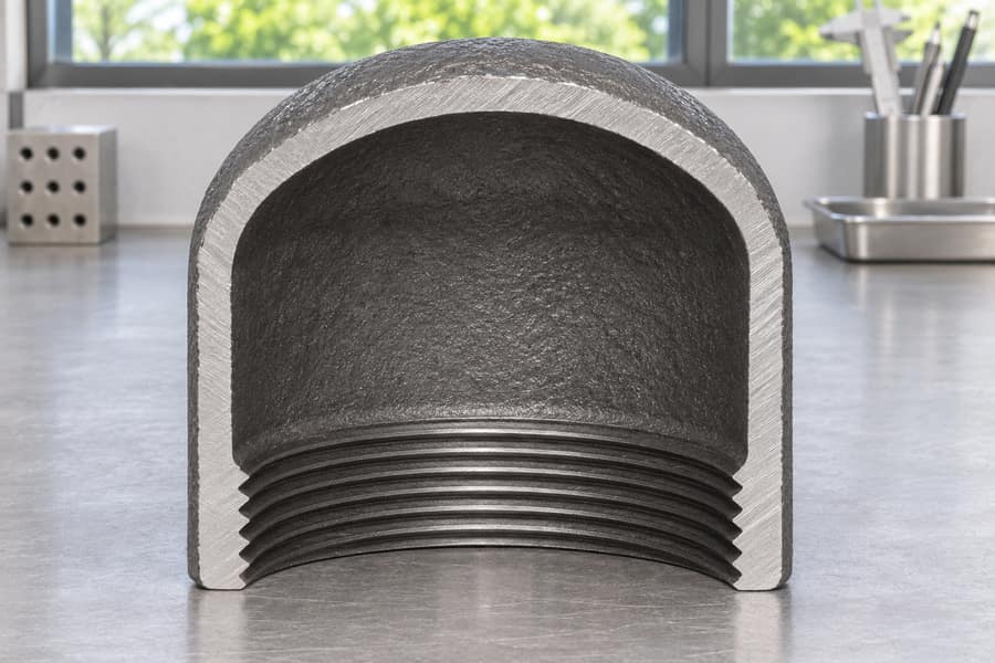
A flat profile may simplify certain manufacturing and dimensional requirements, but it can develop greater bending demand under comparable loading conditions. Its structural adequacy must therefore be evaluated using the actual unsupported span and boundary conditions.
A curved profile can provide a more favorable load distribution in suitable configurations. However, the benefits depend on the curvature, material properties, wall dimensions, and connection stiffness rather than the shape alone.
Corner radii help control abrupt geometric transitions. Extremely sharp internal or external corners can create local stress concentrations, while unsuitable radii may complicate mold design, machining access, or dimensional inspection.
The connection between the cap end and cylindrical body deserves specific attention. Engineers should examine the transition region for local bending, section changes, and potential casting discontinuities.
Detailed drawings should identify critical profiles and dimensions. Where the cap geometry is customized, sectional views help manufacturers understand internal contours, minimum wall requirements, and the intended relationship between the end and connection regions.
External Mechanical Loads and Installation Conditions
Internal pressure is not necessarily the only load affecting a pipeline closure. Handling impacts, installation forces, vibration, and movement within the connected piping system can introduce additional mechanical demands.
Buried pipelines may experience soil-related loading and settlement. These effects depend on burial conditions, surrounding ground characteristics, pipe support, and the movement permitted by the pipeline arrangement.
Thermal expansion can also influence connected components. When pipeline movement is restricted, resulting forces may be transferred to end closures, supports, and joints rather than being accommodated through free movement.
Installation alignment is another consideration. An incorrectly aligned connection can introduce uneven contact or bending loads, especially when installers attempt to force incompatible components into position.
Engineers should identify which loads act directly on the cap and which are transferred through the connected pipe. This distinction helps establish realistic structural boundary conditions and restraint requirements.
Connection Design and Sealing Requirements
Selecting the Appropriate Pipe Cap Connection
The connection arrangement determines how a cap attaches to the pipeline and how loads pass across the interface. Selection should begin with the actual pipe-end configuration and the required joining method.
Female-threaded caps engage externally threaded pipe ends. The thread specification, engagement length, and mating dimensions must be compatible with the connected component and the intended sealing arrangement.
Socket or spigot configurations use different mating geometries. A socket generally receives the corresponding pipe end, while the final joint design determines whether sealing relies on a gasket, mechanical restraint, or another specified arrangement.
Flanged caps require compatibility between the cap flange and the mating pipeline flange. Relevant dimensions include the facing arrangement, bolt-hole pattern, gasket interface, and applicable flange specification.
Custom connections may be developed around project drawings, but availability must be confirmed for the individual manufacturing order. A connection should never be assumed compatible simply because two components share a nominal pipe size.
Dimensional Compatibility and Manufacturing Tolerances
Nominal pipe size identifies a recognized pipe size designation, not necessarily the actual mating dimensions of every component. Engineers must specify the interface dimensions required for reliable assembly.
For threaded caps, relevant details include thread form, nominal designation, pitch where applicable, taper or parallel configuration, and usable engagement. Incorrect thread geometry can prevent proper assembly or compromise the intended seal.
Socket connections require attention to the receiving diameter, insertion depth, and available sealing space. Dimensional variation can affect insertion, gasket compression, alignment, and the final joint position.
Flanged configurations require controlled face dimensions, bolt-hole locations, and gasket seating geometry. A mismatched face or an off-center assembly can unload part of the gasket and leave a route for fluid escape.
Dimension the features that control fit and sealing, and state the permissible variation beside each. Manufacturers need to understand which surfaces control assembly, which dimensions permit adjustment, and which features require machining.
Inspection should use appropriate datums and measurement methods. Measuring overall length without checking the functional connection dimensions may overlook the very deviations that prevent proper installation.
Sealing Methods and Joint Integrity
Sealing requirements depend on the connection type and conveyed medium. Threaded joints may use an appropriate sealing compound or tape, while flanged connections commonly rely on a gasket compressed between mating faces.
Choose a gasket that tolerates the fluid and temperature, then check its pressure limits and its fit against both sealing faces. A gasket that is unsuitable for the medium may deteriorate even when the cap dimensions are correct.
Threaded connections require compatible thread geometry and an appropriate sealing practice. If the threads are damaged, mismatched, or barely engaged, applying more torque does not correct the joint.
For flanged connections, bolt preload must provide suitable gasket compression without damaging the gasket or connection. Fastener selection, flange condition, assembly sequence, and the specified joint procedure all influence performance.
Sealing and mechanical restraint perform different functions. A joint may prevent leakage while still permitting axial movement if its design does not provide sufficient resistance to separation.
The Ductile Iron Pipe Research Association (DIPRA) discusses the distinction between joint sealing and thrust restraint in ductile iron piping systems. This distinction is a useful engineering principle, although product-specific recommendations must remain within their intended application.
Accordingly, the pipeline restraint system should be evaluated independently of the sealing method. Anchors, restrained joints, and other appropriate structural provisions must accommodate the applicable pressure thrust and external loads.
Casting Design, Manufacturing Quality, and Inspection
Casting Geometry and Manufacturability
Cast pipe cap geometry must satisfy structural requirements while remaining practical to manufacture. Mold design, parting lines, draft angles, and section transitions influence the feasibility and consistency of the finished component.
Draft angles help facilitate pattern removal and mold preparation. Their required geometry depends on the casting process and design, so they should be coordinated with dimensional and machining requirements.
Wall sections should avoid unnecessary abrupt thickness changes. Significant differences can produce uneven cooling and solidification, increasing the possibility of shrinkage-related defects or dimensional distortion.
Feeding arrangements are important because metal contracts during solidification. The casting design and production process must allow adequate compensation for shrinkage, particularly around thicker sections and complex connection regions.
Machining allowances should be included where threads, flange faces, or sealing surfaces require finishing. These allowances must not reduce the final component below its specified minimum structural dimensions.
Manufacturability review should take place before production drawings are finalized. Changes to internal contours, corner transitions, or connection details may improve production feasibility without compromising the intended functional requirements.
Common Casting Defects Affecting Pipe Cap Quality
Casting defects can influence both dimensional consistency and structural integrity. Their significance depends on the defect type, location, size, material specification, and intended application of the pipe cap.
- Shrinkage cavities: These form when solidifying metal contracts without adequate feeding. Their location and extent matter because cavities within highly stressed sections may reduce structural integrity.
- Porosity: Gas-related or shrinkage-related pores can occur within the casting. The acceptance of such indications depends on applicable inspection requirements and their effect on the component.
- Inclusions: Nonmetallic material trapped during casting can create local discontinuities. Their significance depends on size, distribution, and position relative to critical load-bearing regions.
- Cold shuts: These occur when separate metal streams fail to fuse properly. Depending on their location and severity, they may compromise the continuity of the casting.
- Cracks: Cracking can develop during solidification, cooling, or subsequent handling. Relevant acceptance requirements should address the nature and location of the discontinuity.
Looking at the cap’s surface cannot confirm that the entire wall is free of hidden flaws. Choose further examination based on the cap’s alloy, section shape, and the defects that the purchase specification requires inspectors to find.
Agree what will cause a casting to be accepted or rejected before production starts. Engineers should avoid treating every visible indication as automatically acceptable or automatically rejectable without considering the governing requirements.
Machining and Dimensional Inspection
Machining is commonly required when a cast surface must meet specific interface dimensions or surface conditions. Threaded regions, flange faces, and gasket seating areas may require controlled finishing.
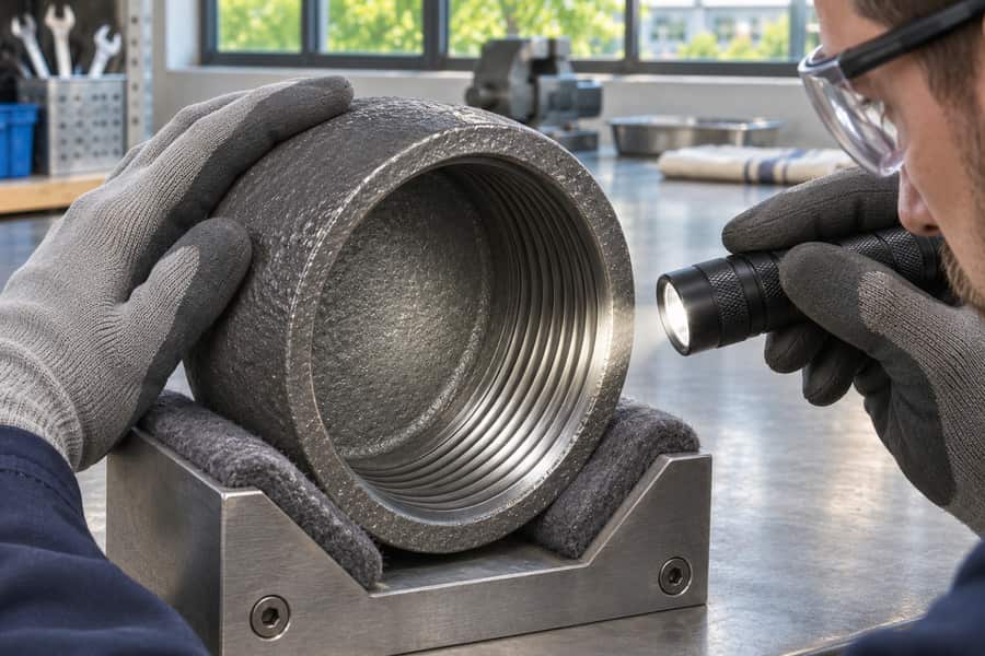
Specify a common datum scheme so the foundry, machine shop, and receiving inspector measure from the same references. Drawings should identify the surfaces and axes used to establish the cap’s functional dimensions.
For threaded connections, inspection should verify the specified thread characteristics and usable engagement. A thread that appears visually acceptable may still fail to mate correctly with the corresponding pipe.
Flanged caps require inspection of face condition, bolt-hole positioning, and relevant dimensional relationships. Gasket seating surfaces should be free from damage that could create leakage paths.
Machining must also preserve the required wall section. Removing excessive material from the connection region can reduce the available structural thickness even when the finished interface dimensions appear correct.
Inspection documentation should identify measured characteristics, acceptance criteria, and applicable material information. Traceability helps connect the finished component with its manufacturing and verification records.
Corrosion Resistance and Surface Protection
Internal Corrosion and Medium Compatibility
The conveyed medium can influence the long-term condition of a cast iron pipe cap. Chemical composition, pH, temperature, dissolved substances, and exposure duration may all affect corrosion behavior.
Drainage applications can involve different chemical and environmental conditions from industrial process pipelines. Engineers should identify the actual fluid characteristics rather than relying on a broad application label.
Corrosion can progressively reduce the available wall section. Where material loss is possible, the design and maintenance assessment should consider the component’s expected exposure and relevant inspection requirements.
Erosion may occur when flowing media carry abrasive particles or produce localized high-velocity conditions. Although a closed cap does not normally function as a flow passage, the inlet region and internal geometry can still experience exposure during operation.
A service-compatible lining or internal coating can separate the conveyed fluid from the iron. Their compatibility with the medium, temperature, preparation method, and intended service should be established before selection.
External Corrosion and Protective Coatings
External corrosion depends on the installation environment. Atmospheric moisture, soil chemistry, groundwater, contaminants, and exposure to dissimilar materials can influence the condition of a cast iron closure.
Buried installations require particular attention to soil conditions and protective system compatibility. A coating suitable for an exposed indoor component may not provide the required protection in a different environment.
Match the protective system to the fluid or external environment and to the cap’s intended duty. Surface preparation, coating thickness, curing, and continuity influence the quality of the completed protection system.
Machined interfaces require additional consideration. Coating application should not interfere with thread engagement, gasket seating, flange contact, or other dimensions that control the mechanical connection.
Consider lifting, packing, and installation contact points where the protective film could be scraped away. Inspection and repair requirements should be established where the protective system is critical to the intended service.
Applicable Standards, Pressure Ratings, and Quality Verification
Understanding Material and Product Standard Requirements
Material specifications and product standards address different aspects of component conformity. A material specification identifies requirements for the metal, while a product standard may define dimensions, construction, marking, or other characteristics.
Engineers should identify the governing pipeline code, applicable material specification, and product requirements before approving a cast iron pipe cap. These documents establish the basis for design review and procurement.
Material grade verification should include the relevant specification and required documentation. Similar material names do not necessarily indicate equivalent mechanical properties or interchangeable service suitability.
Product dimensions alone cannot establish pressure qualification. A cap that matches a recognized pipe size may still require separate engineering evaluation of its material, geometry, connection, and intended operating conditions.
The project specification should also distinguish design pressure from ordinary operating pressure. This distinction helps ensure that component selection and verification reflect the complete design basis.
ASME B16.4 and B16.12: Scope and Limitations
ASME B16.4 addresses gray iron threaded fittings in Classes 125 and 250. Its scope is relevant to the specified category of threaded fittings, rather than providing a universal design basis for every cast iron end closure.
For threaded cast-iron drainage components, check the scope and requirements of ASME B16.12. Its application should be considered within the drainage-fitting scope and the corresponding project requirements.
A fitting’s material and intended duty determine which of these documents applies. Their material and product scopes differ, and engineers must verify whether the actual cap configuration falls within the applicable standard.
A component should not be assigned a standard designation merely because its external dimensions resemble a standardized fitting. Material, connection type, product category, and intended service must all be considered.
Class designations also require careful interpretation. They should not be converted into a generic allowable pressure for a custom cast component without confirming the applicable standard, material, temperature conditions, and product scope.
The governing edition should be stated in procurement documents. Where project specifications adopt a particular edition, manufacturers and inspectors should use that edition when evaluating conformity and acceptance.
Pressure Qualification and Inspection Requirements
Pressure qualification requires a defined engineering basis. Calculations address the design assumptions; material records, measurements, and pressure tests check other aspects of the delivered cap. None alone verifies every requirement.
Design calculations evaluate the component against specified loading conditions and applicable material requirements. They should consider the cap body, connection region, joint arrangement, and load transfer into the pipeline.
Pressure testing, where required, verifies behavior under a specified test condition. The applicable test standard or project procedure must establish the method, acceptance criteria, and documentation requirements.
Testing a completed pipeline does not automatically demonstrate that every component has been independently qualified for all possible operating conditions. Test results must be interpreted within the actual system configuration and governing requirements.
Test procedures should also address safe isolation, controlled pressurization, monitoring, and depressurization. No universal test pressure or procedure should be assumed without reference to the applicable specification.
Inspection records should identify the material, relevant dimensions, examination results, and testing evidence where required. These records support traceability and provide a basis for evaluating the delivered component against procurement requirements.
Technical Specifications for Custom Cast Iron Pipe Caps
Essential Design Information for Manufacturing
A manufacturing inquiry should provide enough information to define the component’s physical interface and intended service. Incomplete specifications can lead to incorrect assumptions about dimensions, materials, and connection requirements.
Nominal pipe size should be accompanied by actual mating dimensions where these control assembly. Connection details should identify whether the cap is threaded, socket-type, flanged, or designed for another specified interface.
Material information should identify the required material family and grade. Where a project requires specific mechanical properties or material documentation, these requirements should be stated explicitly.
Operating conditions are equally important. Design pressure and temperature, conveyed medium, environmental exposure, and relevant load cases provide the engineering context needed to evaluate suitability.
Procurement documents should also identify the applicable standards and required verification. Include examination, traceability, finish, test conditions, and required records in the order before manufacturing is released.
The following table summarizes the information that engineers and technical buyers should prepare when requesting a custom pipe cap.
| Design category | Required information | Engineering purpose |
| Material | Material family, grade, and applicable specification | Establish mechanical and application suitability |
| Geometry | Cap profile, overall dimensions, and wall requirements | Define structural configuration |
| Connection | Joint type, mating dimensions, and engagement details | Ensure interface compatibility |
| Sealing | Gasket, thread, or other sealing requirements | Define the leakage-control arrangement |
| Operating conditions | Design pressure, temperature, medium, and relevant loads | Establish the design basis |
| Corrosion protection | Internal or external coating and lining requirements | Address environmental exposure |
| Standards | Applicable material, product, and project specifications | Establish conformity requirements |
| Inspection | Dimensional checks, material verification, and required testing | Define acceptance and documentation |
Engineering Drawings and Customization Requirements
Sectional drawings are particularly useful for cast pipe caps because external views cannot fully communicate internal geometry. They should show the closed-end profile, body dimensions, connection arrangement, and relevant wall sections.
Give each fit-sensitive feature a drawing dimension and an explicit allowable variation. These may include mating diameters, thread details, insertion depth, flange dimensions, and the location of functional sealing surfaces.
Drawings should distinguish finished dimensions from casting dimensions where machining is required. This helps manufacturers allocate machining allowances without compromising the final structural requirements.
Where pressure service is intended, the drawing package should identify the design conditions and governing qualification basis. A drawing that provides only nominal size and external dimensions is insufficient for a complete engineering assessment.
Inspection requirements should accompany the drawings. They should identify which characteristics require measurement, what acceptance criteria apply, and which records must be supplied with the finished component.
Custom Metal Pipe Fitting Manufacturing Considerations
Boberry Machining offers custom metal pipe fittings, with material and connection options determined according to individual order requirements. The site’s metal fitting categories cover direction changes, branch connections, diameter transitions, and pipe joining.
For a custom pipe cap inquiry, the initial discussion should establish the required component configuration, material specification, mating interface, and finished dimensions. Use those details for a manufacturing review of the proposed cap, including its casting geometry and finished interfaces.
Material selection should remain tied to the actual application. The presence of gray cast iron within a drainage and ventilation product category does not establish that a custom gray iron cap is suitable for pressurized service.
Similarly, a proposed connection or external profile should not be interpreted as an existing standard product capability. Specific manufacturing feasibility, material availability, and inspection arrangements require confirmation against the individual order.
Engineers and buyers should therefore provide a sectional drawing, pipe-end dimensions, material requirements, operating conditions, applicable standards, and inspection expectations when requesting a quotation or technical review.