
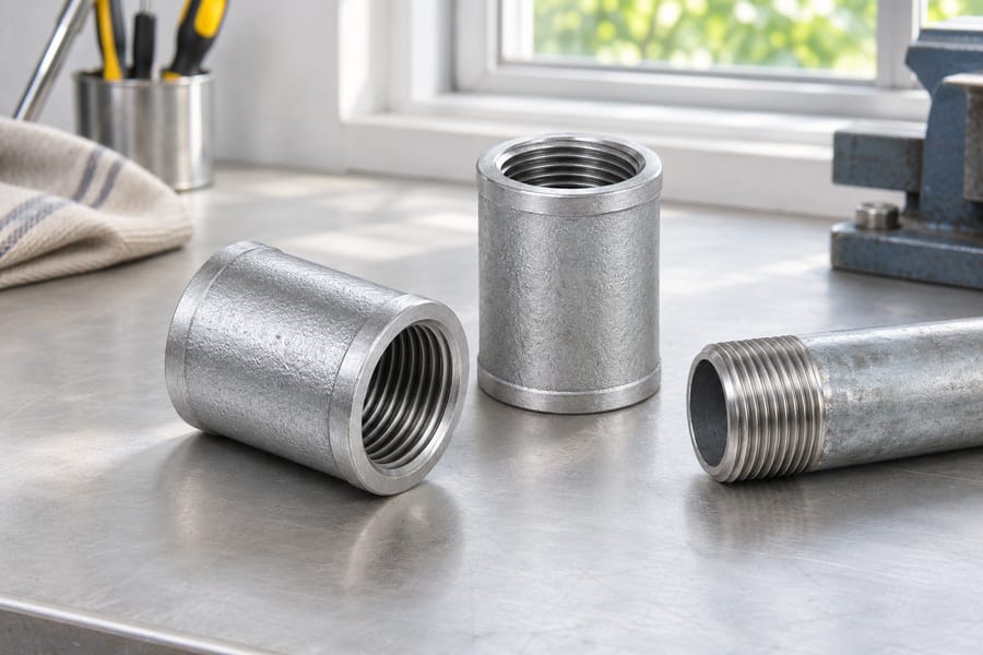
Cast pipe couplings join pipe ends through defined engagement and sealing interfaces. Their geometry controls alignment, gasket compression, and the joint’s ability to accommodate specified movement and loads.
Selection requires more than matching nominal pipe size: engineers must verify mating dimensions, connection type, gasket compatibility, material, and documented service limits.
Understanding Cast Pipe Couplings and Their Connection Functions
What Is a Cast Pipe Coupling?
A cast pipe coupling is a connecting component designed to join two pipe sections through compatible end geometries. Its body may incorporate sockets, threads, flanges, or other interfaces that determine how the mating components engage.
The coupling itself is not necessarily a complete joint. Depending on the design, the assembled connection may also require gaskets, glands, bolts, sealants, or separate restraint components. These elements perform different functions and must be evaluated together.
For engineering purposes, three functions deserve separate consideration: maintaining the physical connection, preventing fluid leakage, and resisting mechanical separation. A leak-tight interface may still need a separate means of holding the pipe against end thrust.
Main Connection Configurations
Cast pipe couplings use several connection configurations, each with different requirements for dimensional compatibility and sealing. Common arrangements include socket and spigot, threaded, mechanical joint, flanged, and grooved connections.
The terminology can vary between product specifications. A one-piece threaded coupling, for example, differs structurally from a union, while a grooved coupling normally uses a segmented housing assembled around prepared pipe ends.
How Connection Geometry Affects Joint Performance
Connection geometry determines the contact surfaces, engagement depth, and available space for sealing components. Small dimensional mismatches can change gasket compression or thread engagement, creating leakage paths even when the nominal pipe sizes match.
Geometry also influences alignment and load transfer. An incorrectly positioned coupling may introduce angular misalignment, uneven contact pressure, or additional bending loads at the pipe ends.
Sealing and axial restraint must remain separate design checks. A leak-tight gasket does not automatically prevent a pipe from pulling out under pressure-generated thrust or external loading. DIPRA technical guidance distinguishes joint sealing from the requirements for thrust restraint, an important distinction when specifying mechanical connections.
Connection Geometry and Structural Design of Cast Pipe Couplings
Socket and Spigot Geometry
A socket and spigot connection uses a receiving socket at one end and a matching pipe end at the other. The socket provides an engagement region, while its internal profile accommodates the sealing arrangement specified for the joint.
Important dimensions include socket inside diameter, socket depth, spigot outside diameter, and the position of any internal shoulder or gasket groove. Their relationship determines whether the pipe can enter correctly and whether the sealing element occupies its intended position.
In a gasketed socket, the spigot compresses a resilient ring against the receiving bore. Others incorporate different sealing arrangements, so the required insertion position must come from the applicable joint design rather than a universal depth assumption.
An insertion stop or reference mark can help installers achieve repeatable positioning. However, excessive insertion may also affect movement allowance or interfere with internal components, depending on the connection configuration.
Threaded Coupling Geometry
A one-piece female threaded coupling generally connects two externally threaded pipe ends through internal threads at opposite ends. The body provides a continuous connecting component, without the separate union nut and mating seat arrangement found in a union.
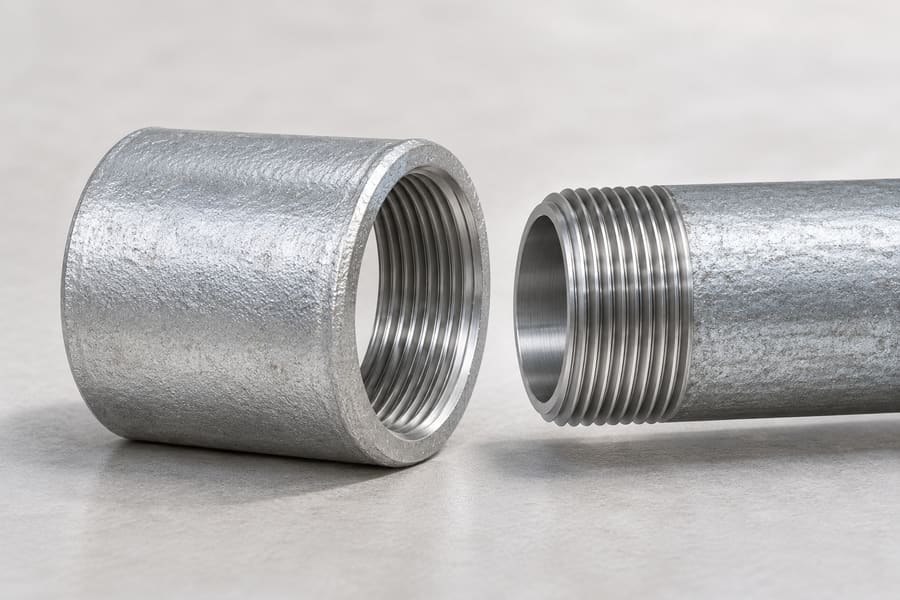
A union adds a separable connector so the joint can be opened while the adjoining pipes stay in position. This distinction matters when installation space is limited or equipment requires periodic removal.
Thread geometry must match the specified thread system. NPT, BSPT, and BSPP configurations differ in thread form, pitch, diameter relationships, or taper. Their dimensional compatibility cannot be assumed simply because the nominal sizes appear identical.
Thread engagement, flank contact, and the intended sealing mechanism determine joint behavior. Excessive tightening can damage threads or overstress a cast component, while insufficient engagement may compromise both mechanical connection and sealing.
Mechanical Joint Geometry
A typical mechanical joint uses a bell, spigot, elastomeric gasket, gland, and fastening components. The spigot enters the bell, and the gland applies compression to the gasket against the designated sealing surfaces.
The bell dimensions establish the available space for the gasket and gland. Bolt-hole positioning, gland geometry, and the relationship between the pipe outside diameter and the joint components influence how evenly the gasket is compressed.
Mechanical joints may accommodate some angular deflection or installation movement, depending on their design. However, movement capability and axial restraint must be verified separately because an ordinary sealing arrangement may not provide positive resistance to joint separation.
Where pressure-generated thrust or external loads could cause movement, the specification must identify the required restraint arrangement. This may involve a specifically designed restrained joint or separate restraint components rather than relying on gasket friction alone.
Flanged Connection Geometry
Flanged connections use mating flange faces secured by bolts, with a gasket positioned between the sealing surfaces. A cast coupling or connector may incorporate flange ends when the required system configuration calls for a bolted interface.
Check the flange rim diameter and section thickness, then verify the drilling pattern, including bolt pitch circle and hole diameters. Face type and gasket seating dimensions must also correspond to the mating component.
Misaligned bolt holes can introduce assembly stress, while uneven flange faces may prevent uniform gasket compression. Engineers should therefore check both dimensional compatibility and the condition of the sealing surfaces before installation.
Flanged connections also require consideration of bolt loading and the stiffness of the connected components. The selected gasket, flange materials, operating conditions, and assembly procedure determine the appropriate joint arrangement.
Grooved Coupling Geometry
A grooved coupling connects prepared pipe ends through a gasket and a housing that engages the external grooves. Unlike a one-piece female threaded coupling, its housing normally consists of multiple segments secured by bolts or other specified fastening components.
The gasket surrounds the pipe ends and occupies the housing cavity. Housing keys engage the prepared grooves, establishing the mechanical relationship between the coupling assembly and the pipes.
Groove width, depth, diameter, and location must match the coupling requirements. Incorrect groove preparation can prevent proper housing engagement or change gasket positioning, even when the pipe outside diameter is otherwise acceptable.
Grooved couplings may be designed as rigid or flexible connections. A rigid configuration limits relative movement, whereas a flexible design may accommodate specified angular or axial movement. These characteristics are product-specific and should not be inferred from appearance alone.
Internal bore transitions also deserve attention when flow conditions are important. The U.S. Department of Energy’s fluid-flow guidance treats fittings and geometric disturbances as sources of local pressure loss.
An internal step, offset, or gasket intrusion can therefore influence flow, although the actual effect depends on geometry and operating conditions.
Critical Dimensions and Tolerances for Coupling Compatibility
Nominal Pipe Size vs. Actual Outside Diameter
Nominal pipe size identifies a pipe’s standardized size designation, not necessarily its directly measurable outside diameter. Coupling compatibility must therefore be established using the actual dimensional series and the applicable pipe specification.
Two components carrying the same nominal size designation may have different connection requirements if they follow different dimensional standards. Engineers should confirm the actual pipe outside diameter, coupling bore, and specified tolerances before approving an assembly.
For cast components, dimensional checks should also consider machining allowances and casting variation. The finished connection interface, rather than the nominal casting dimension, determines whether the coupling can engage its mating pipe correctly.
Engagement Length and Connection Clearance
Engagement length describes how much of the mating component participates in the connection. For socket joints, it relates to insertion depth; for threaded joints, it concerns effective thread engagement; for grooved joints, it relates to the prepared pipe-end geometry and housing position.
Insufficient engagement can reduce the available sealing contact or compromise mechanical connection. Excessive engagement may interfere with internal stops, gasket positioning, or movement allowances designed into the joint.
Installation clearances also influence assembly. Engineers should consider access for tightening, room for gland movement, gasket placement, and the ability to align pipe ends without forcing the coupling into position.
Take the insertion limits, engaged thread length, and groove location from the approved joint drawing. No single insertion distance, number of thread turns, or clearance value applies to every cast coupling design.
Concentricity, Roundness, and Surface Accuracy
Concentricity describes the relationship between the coupling bore and its external or functional reference geometry. Poor concentricity can produce uneven wall sections or misalignment between mating components, affecting assembly and sealing contact.
Roundness is equally important at the pipe interface. An oval pipe end may compress a gasket differently around its circumference, leaving localized areas with insufficient contact or excessive deformation.
Angular misalignment can create similar problems. When connected pipe ends do not follow the intended alignment, the gasket may experience uneven loading, and the coupling may carry additional bending forces.
Inspect the surface where that particular joint actually forms its seal. Threaded surfaces require the specified thread profile and finish, while gasket seating areas must remain free from defects that could interrupt continuous contact.
Coupling Body Thickness and Casting Geometry
Wall-section geometry influences the structural behavior of a cast coupling. Changes in section thickness around sockets, threaded regions, flange transitions, and bolt locations can create areas that require particular attention during design and inspection.
Casting geometry should account for the manufacturing process and subsequent machining. Machining stock must be sufficient to produce the specified connection dimensions without compromising the intended finished section.
Local thickness variation, shrinkage, porosity, and other casting discontinuities may affect structural integrity. Inspection requirements should therefore identify critical load-bearing and sealing regions rather than relying exclusively on external appearance.
Body thickness alone cannot establish a pressure rating. Pressure suitability depends on the complete design, material grade, manufacturing quality, applicable product requirements, and documented qualification for the intended service.
Table 1: Connection Geometry and Critical Dimensional Requirements
| Connection type | Main geometric features | Critical dimensional checks | Sealing interface | Common compatibility problems |
| Socket and spigot | Receiving socket, spigot, internal shoulder, and gasket groove | Socket diameter, insertion depth, spigot diameter, and groove position | Elastomeric gasket or specified socket sealing arrangement | Incorrect insertion, diameter mismatch, and uneven gasket compression |
| Threaded | Internal and external thread profiles | Thread form, pitch, diameter, taper, and engagement | Thread interference with compatible sealant or a separate sealing interface | Incompatible thread systems, damaged threads, and insufficient engagement |
| Mechanical joint | Bell, spigot, gasket, gland, and fasteners | Bell dimensions, gland position, bolt arrangement, and pipe outside diameter | Compressed elastomeric gasket | Uneven compression, incorrect gland positioning, and inadequate restraint |
| Flanged | Mating flange faces, bolt holes, and gasket seating surfaces | Flange dimensions, bolt-circle diameter, face alignment, and gasket area | Gasket between mating flange faces | Bolt-hole mismatch, damaged faces, and uneven gasket loading |
| Grooved | Segmented housing, pipe grooves, and gasket cavity | Groove diameter, width, depth, and location | Elastomeric gasket inside the housing | Incorrect groove preparation, housing misalignment, and gasket displacement |
Sealing Mechanisms and Gasket Requirements
Elastomeric Gasket Sealing
Elastomeric gaskets seal by deforming against designated mating surfaces. Their cross-sectional shape and installed position determine how compression develops and whether continuous contact can be maintained around the joint.
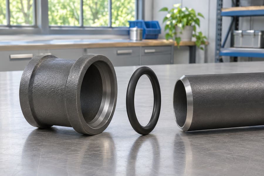
In socket and spigot connections, the gasket may be compressed radially between the socket and pipe exterior. Mechanical joints use a different arrangement in which the gland applies compression to the gasket within the bell.
Gasket selection must account for the conveyed medium, temperature, pressure, and expected movement. Chemical incompatibility can cause swelling, hardening, softening, or other changes that reduce sealing reliability.
Compression set is another important consideration. An elastomer that loses its ability to recover after prolonged deformation may provide less contact pressure over time, particularly when operating conditions accelerate material aging.
Threaded Connection Sealing
Threaded joints do not all seal through the same mechanism. Tapered threads can develop interference between mating thread flanks, while other configurations rely on a separate gasket, washer, or sealing face.
For NPT connections, the specified tapered thread geometry and compatible sealant contribute to the intended sealing arrangement. BSPT and BSPP connections follow different dimensional and sealing conventions, so substitution without verification can produce unreliable engagement.
Parallel threads are not automatically pressure-tight through their thread contact alone. Some parallel-thread systems require a separate sealing element at a shoulder or face, while other arrangements use a specified gasket or washer.
Sealant selection should reflect the thread system and conveyed medium. The wrong compound can attack a gasket, change assembly friction, or compromise the seal over time.
Installers should follow the specified engagement and assembly procedure rather than applying a universal torque or number of turns. Excessive tightening can damage cast threads, distort components, or introduce unnecessary stress into the coupling body.
Flange and Mechanical Joint Sealing
Flanged joints rely on controlled compression of a gasket between two mating faces. Gasket material, thickness, dimensions, and surface compatibility determine how the sealing interface responds to assembly loading and operating conditions.
Flange faces must provide suitable contact across the intended gasket area. Scratches, corrosion, distortion, or uneven surface conditions can create localized leakage paths even when the bolt arrangement is dimensionally correct.
Mechanical joints use a different compression arrangement. The gland transfers fastening force to the gasket, which deforms against the bell and spigot surfaces to establish the seal.
Uniform fastening helps maintain consistent gasket compression. However, fastening requirements must follow the specific joint design because component geometry, bolt characteristics, and gasket properties vary between products.
Neither flange gasket compression nor mechanical joint sealing should be treated as automatic axial restraint. Where the pipeline requires resistance to pressure thrust or external separation forces, the joint must include an appropriately qualified restraint arrangement.
Grooved Coupling Sealing
In grooved connections, the gasket sits inside the segmented housing and contacts the external surfaces of the pipe ends. The housing compresses and supports the gasket while its keys engage the pipe grooves.
Correct gasket placement is essential. A displaced, twisted, contaminated, or damaged gasket may prevent continuous contact and create a leakage path after assembly.
Pipe-end preparation must also match the housing requirements. Groove dimensions, edge condition, and the distance between the groove and pipe end influence whether the housing can engage correctly without interfering with the gasket.
Rigid and flexible grooved designs may accommodate different amounts of movement. Engineers should verify the specified movement limits and restraint behavior instead of assuming that every grooved coupling provides the same mechanical characteristics.
Factors Affecting Gasket Selection
Gasket selection begins with the fluid and its chemical properties. Water, oils, cleaning chemicals, solvents, and process fluids may interact differently with the same elastomer, making general material descriptions insufficient for final selection.
Temperature influences both the gasket’s physical properties and its ability to maintain contact pressure. Pressure changes and repeated operating cycles can also affect deformation and sealing stability.
Mechanical conditions matter alongside fluid compatibility. Vibration, angular deflection, thermal movement, and repeated pressure fluctuations may increase stress on the sealing interface.
Select the seal as a complete part: its compound and hardness must suit the fluid, while its cross-section and size must fit the joint. A material described as chemically resistant may still be unsuitable if its temperature range or compression behavior does not match the application.
Common Leakage Causes and Their Relationship to Geometry
Many leakage problems originate from incompatibility between the coupling and its mating components. Incorrect outside diameter, socket dimensions, thread form, or groove preparation can prevent the joint from reaching its intended assembled condition.
Other failures develop at the sealing interface itself. Damaged surfaces, contaminated gaskets, incorrect gasket dimensions, and uneven compression can interrupt contact around the connection.
Installation conditions can introduce additional problems. Misaligned pipe ends, forced assembly, excessive tightening, or incorrect gasket positioning may create stresses that were not considered in the original connection design.
Leakage investigation should identify the actual failure mechanism before replacing components. Checking dimensions, gasket condition, assembly position, and pipeline movement provides a more useful diagnosis than automatically increasing fastening force.
How Casting Materials Influence Coupling Design
Gray Cast Iron
Gray cast iron contains graphite in flake form, giving it characteristic casting and machining properties. Its relatively limited ductility makes deformation and impact resistance important considerations when designing connection sections.
Machined sealing interfaces must maintain the specified geometry because cracking or localized damage can compromise the connection. Threaded sections, socket transitions, and thin local features deserve particular attention during inspection.
Gray cast iron should only be selected where its documented material and product specifications suit the intended service. For example, the gray cast iron category described by Boberry Machining is intended for non-pressurized drainage and venting applications; this description should not be interpreted as a general pressure-rating statement.
Ductile Cast Iron
Ductile cast iron contains graphite in nodular form, generally providing greater ductility and toughness than gray cast iron. The resulting material behavior matters when assessing assembly forces and service loading.
Material grade, casting quality, and finished dimensions remain essential. A ductile iron designation alone does not establish suitability for every pressure, temperature, or chemical environment.
Machined connection areas require dimensional verification, particularly where gasket compression or threaded engagement depends on accurate geometry. The material specification and applicable product requirements should define the necessary mechanical and inspection criteria.
Heat-Treated Malleable Iron Bodies
Malleable iron begins as a white-iron casting; subsequent annealing changes its carbon structure and gives the finished material its characteristic properties. It may be used for threaded connection components where the relevant grade and product specification permit its application.
Thread integrity is particularly important because the connection depends on accurate engagement between mating surfaces. Machining quality, material condition, and the specified thread system must be checked together.
Its use should be evaluated according to the actual coupling design and service requirements rather than assumed interchangeable with gray or ductile iron.
Cast Steel
Cast steel differs from cast iron in its carbon content, microstructure, and grade-dependent mechanical properties. It can provide different design options, but its suitability still depends on the specified material grade and manufacturing requirements.
Connection surfaces may require machining to achieve the necessary thread, flange, socket, or gasket geometry. Casting discontinuities and local section variations should be evaluated according to the component’s structural requirements.
Cast steel should not be treated as equivalent to forged steel simply because both materials can produce components with similar external shapes. Their manufacturing routes and applicable product specifications must be identified correctly.
Standards, Inspection, and Sealing Performance Verification
Understanding Applicable Dimensional Standards
Standards establish requirements within defined product and material scopes. Before applying a dimensional standard to a cast pipe coupling, engineers should confirm that the document actually covers the component’s material, construction method, and connection configuration.
ASME B16.9 covers factory-made wrought buttwelding fittings, while ASME B16.11 addresses forged fittings. Neither standard establishes a cast coupling’s pressure rating simply because its dimensions resemble those of a covered product.
For threaded fittings, material-specific standards may be relevant. ASME B16.3 addresses malleable iron threaded fittings, and ASME B16.4 addresses gray iron threaded fittings. Their applicability must be checked against the actual product type and specification.
Thread requirements also need separate verification. ASME B1.20.1 addresses general-purpose inch pipe threads, including NPT. Other thread systems follow their own dimensional and sealing conventions, so a drawing should identify the exact thread designation and applicable standard.
Standards compliance should never be inferred from nominal size or visual similarity. Engineers must establish which requirements apply to the complete coupling assembly and which apply only to an individual component.
Checking the Finished Coupling
Start dimensional inspection at the pipe and seal contact features, where a small error can prevent a sound joint. Depending on the design, this includes bore diameter, outside diameter, socket depth, thread profile, flange dimensions, and groove geometry.
Measurement methods must be suitable for the feature being checked. Thread gauges, calibrated dimensional instruments, and appropriate surface inspection methods provide different information and should be selected according to the drawing requirements.
Casting inspection should examine relevant discontinuities such as cracks, shrinkage, and porosity. The acceptance criteria depend on the material, manufacturing specification, component geometry, and intended service.
Inspect threads, grooves, and gasket seats after machining; a sound raw casting does not guarantee an accurate finished interface. Inspection should confirm that machining has produced the required sealing and engagement geometry without creating unacceptable local defects.
Gasket and Joint Performance Verification
Gasket verification should confirm material identification, dimensions, condition, and compatibility with the intended fluid. The inspection should also establish that the gasket profile matches the coupling cavity or sealing surface.
Assembly checks should examine pipe alignment, gasket positioning, engagement, and fastening condition. Where restraint is required, the inspection must additionally confirm that the specified restraint components are present and correctly installed.
Use the specified joint test procedure and judge leakage against the acceptance limits agreed for that product. Test conditions must be appropriate for the complete assembly, including its material, gasket, fasteners, and mating components.
A successful leakage test demonstrates performance under the tested conditions, not unlimited suitability for other pressures, temperatures, or fluids. Test documentation should identify the test method, conditions, results, and acceptance basis.
How to Specify a Custom Cast Pipe Coupling
Essential Drawing and Dimensional Information
A useful coupling inquiry begins with the mating pipe information rather than a nominal size alone. Provide the actual outside diameter, pipe specification, wall thickness where relevant, and details of the existing connection.
The drawing should identify the required coupling configuration and all functional interface dimensions. For socket connections, show socket geometry and insertion requirements; for threaded designs, specify the thread system, size, and engagement requirements.
Flanged designs require mating-face dimensions and bolt arrangements, while grooved designs need the applicable groove profile and pipe-end preparation details. These features should be dimensioned from clear reference datums.
Critical tolerances should distinguish functional requirements from noncritical external dimensions. This helps manufacturers concentrate inspection on the features that control assembly, sealing, and mechanical compatibility.
Material and Sealing Specifications
Material selection should identify the required casting material and grade, together with any applicable material specification. Avoid using broad descriptions such as cast iron without distinguishing gray, ductile, or malleable iron.
Sealing information should identify the gasket type, material, profile, and dimensional requirements. The conveyed medium, chemical exposure, design temperature, and pressure conditions help establish whether the proposed sealing arrangement is suitable.
Mechanical requirements should also be documented. Identify whether the joint must accommodate angular deflection, axial movement, vibration, or pressure-generated thrust, and specify whether separate restraint is necessary.
These details prevent an important specification gap: selecting a coupling that seals correctly during assembly but does not satisfy the pipeline’s mechanical requirements during operation.
Manufacturing and Quality Requirements
Manufacturing documentation should define the required casting material, critical dimensions, machining operations, and inspection criteria. If particular casting discontinuities are unacceptable, the drawing or purchase specification should identify the relevant acceptance requirements.
Put the test plan in the purchase specification before the coupling enters production. Identify whether dimensional inspection, material documentation, visual examination, or leakage and pressure testing are required.
The acceptance process should distinguish component verification from complete joint verification. A correctly machined coupling body does not independently demonstrate that the assembled connection will seal with a particular pipe and gasket.
Clear documentation also helps resolve responsibility for mating components. The coupling manufacturer, pipe supplier, gasket supplier, and installer may each control different parts of the final connection.
Custom Metal Pipe Fitting Capabilities at Boberry Machining
Boberry Machining offers custom metal pipe fittings, with material and connection options determined according to individual order requirements. The site groups its metal pipe fittings by functions such as changing direction, branching, changing diameter, and joining pipe ends.
For a custom cast coupling inquiry, the required material, connection geometry, mating dimensions, and sealing arrangement should be defined before manufacturing feasibility is confirmed. Specific product availability and technical capabilities must be established for the actual order.
Buyers should provide a dimensioned drawing, mating pipe specifications, intended service conditions, and applicable inspection requirements. These details allow the proposed coupling configuration to be evaluated without assuming that a similar-looking fitting has the same material properties or pressure capability.
Table 2: Cast Pipe Coupling Specification and Inspection Checklist
| Specification category | Information to provide | Details to verify |
| Material | Gray iron, ductile iron, malleable iron, or specified cast steel grade | Material designation, mechanical requirements, and applicable documentation |
| Connection geometry | Socket, threaded, mechanical joint, flanged, or grooved configuration | Interface dimensions, engagement, alignment, and component compatibility |
| Dimensional requirements | Pipe outside diameter, bore, insertion dimensions, thread details, and tolerances | Critical dimensions, machining accuracy, concentricity, and roundness |
| Sealing components | Gasket profile, material, dimensions, or specified thread sealant | Fluid compatibility, temperature suitability, gasket positioning, and compression |
| Operating conditions | Design pressure, design temperature, conveyed medium, and mechanical loads | Documented service limits, movement requirements, and axial restraint provisions |
| Manufacturing requirements | Casting requirements, machining details, surface specifications, and drawing references | As-cast soundness and machined features checked against the released drawing |
| Required examinations | Dimensional checks, material records, examination methods, and required tests | Acceptance criteria, test conditions, results, and traceable inspection records |
Before requesting a quotation, engineers should submit the mating pipe drawing, connection dimensions, material grade, gasket requirements, operating conditions, and inspection criteria. With these inputs, the drawing review can address both the pipe fit and the proposed seal before a coupling is ordered.