
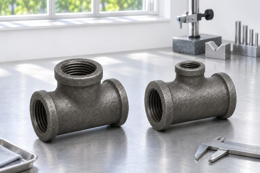
A cast pipe tee connects a branch to a main run, creating an intersection where flow paths, pressure loads, and casting conditions meet.
Reliable design therefore depends on branch geometry and local wall thickness, assessed alongside material, manufacturing tolerances, machining allowances, and the fitting’s specified service and applicable qualification requirements.
The Run, Branch, and Junction of a Cast Tee
A cast tee provides a third opening off a two-ended run, allowing another pipe to join the main line. Its geometry determines how the flow passages intersect and how material is distributed around the junction.
Unlike a straight pipe section, a tee contains an opening through the main run wall. This interruption creates a structurally complex region where internal pressure, external piping loads, and manufacturing variations must be considered together.
Matching or Reducing the Branch Size
An equal tee carries one nominal size across its run and branch openings. Their branch and run passages are generally designed around comparable nominal dimensions, although actual internal bores depend on wall thickness and manufacturing specifications.
Reducing tees have a smaller nominal branch than the main run. The difference affects the opening geometry, remaining run material, branch neck dimensions, and transition profile around the intersection.
Both forms still need a drawing: a nominal size designation leaves many dimensions unspecified. Engineers should establish the required outside diameters, internal bores, center-to-end dimensions, and wall thickness independently.
The distinction also matters when evaluating local reinforcement. A smaller branch opening removes less material from the run than a larger opening, but the required reinforcement still depends on design conditions and the applicable calculation method.
Main Structural Regions of a Cast Pipe Tee
The main run forms the continuous passage through the fitting, while the branch neck connects the side opening to the external pipeline. Both regions contribute to the pressure boundary.
At their intersection, the internal crotch and external heel create different geometric conditions. The crotch affects internal flow and local material transitions, whereas the heel influences external contour and material distribution.
These regions should be identified separately on engineering drawings. A single overall wall thickness dimension cannot adequately describe the local geometry of a complex cast junction.
Branch Geometry Design and Its Effects on Tee Performance
Branch Diameter and Run-to-Branch Ratio
Branch diameter influences both the flow area and the amount of material interrupted in the main run. Increasing the opening changes the geometry of the junction and can increase local structural demands.
The run-to-branch size relationship should therefore be evaluated using actual passage dimensions rather than nominal sizes alone. Differences in wall thickness can produce different internal area ratios even when nominal configurations appear similar.
For reducing tees, the smaller branch may create a more restricted passage. However, its actual hydraulic behavior depends on the complete junction contour, upstream conditions, flow direction, and operating flow distribution.
Engineers should also consider whether the branch carries a substantial portion of the system flow. A branch used for a small auxiliary stream presents different hydraulic conditions from one handling a significant portion of the total flow.
Branch Angle and Centerline Alignment
Many conventional tees use a branch positioned approximately perpendicular to the main run. Other branch orientations may be required by specialized piping arrangements or equipment connections.
Changing the branch angle changes the intersection geometry and the direction in which fluid enters or leaves the run. It can also alter the shape and location of the crotch and heel regions.
Centerline alignment is equally important for installation. Incorrect branch orientation can introduce assembly interference, misalignment, and additional loads when connected piping is forced into position.
Engineering drawings should identify the branch angle, centerline location, and relevant dimensional datums. These details allow the foundry and inspection team to evaluate the intended geometry consistently.
Crotch Radius and Internal Junction Transitions
The crotch is the internal region where the branch passage meets the main run. Its shape affects local flow behavior and the distribution of material around the branch opening.
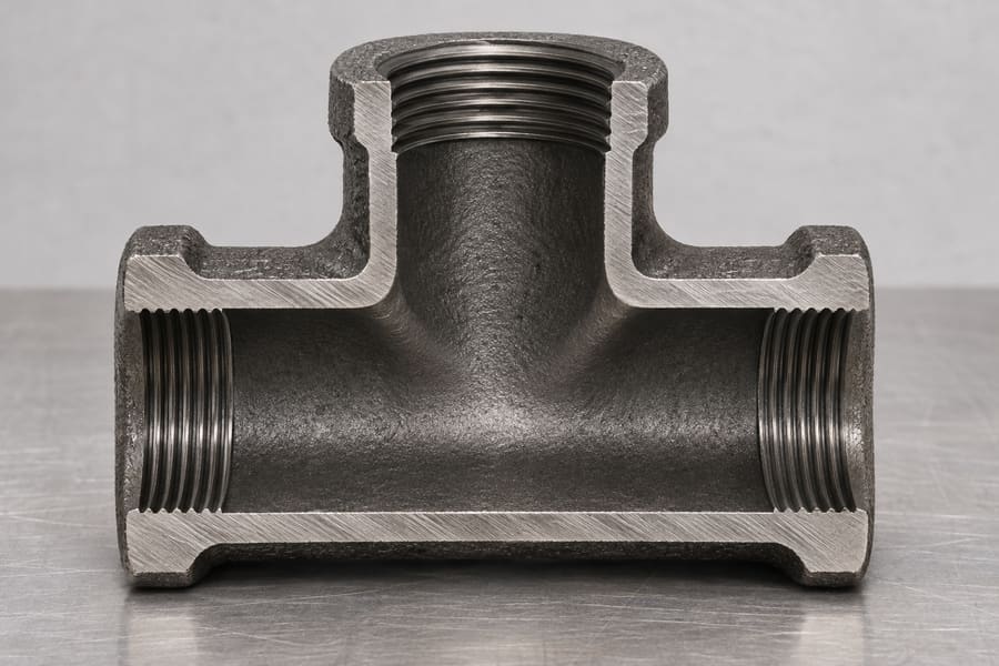
An abrupt internal transition can encourage flow separation and recirculation, particularly when fluid changes direction through the junction. These effects may contribute to additional pressure loss and localized turbulence.
From a structural perspective, abrupt geometric changes can concentrate stress around the intersection. A suitable transition radius helps avoid unnecessarily sharp changes in geometry and supports a more gradual material transition.
A larger crotch fillet can also create space and casting constraints. The available passage area, branch dimensions, casting method, core arrangement, and required wall thickness all influence the practical geometry.
The radius should therefore be established as part of the overall tee design rather than selected independently. Internal passage requirements and external material distribution must remain compatible.
Heel Geometry and External Transitions
The external heel is the outer region opposite the internal branch intersection. Its contour influences how the branch neck transitions into the main run and how material is distributed around the junction.
A sharp external transition can create an unfavorable local stress concentration. Gradual contours and suitable fillets can improve geometric continuity while avoiding unnecessary changes in section thickness.
Heel geometry also affects mold design and solidification. Excessively thick external regions may cool differently from neighboring sections, potentially creating localized shrinkage or internal discontinuities.
Engineers should evaluate the external heel together with the internal crotch. Optimizing only one surface can produce an unfavorable wall distribution on the opposite side of the casting.
Relationship Between Branch Geometry, Flow and Structural Stress
Flow through a tee can involve either dividing or combining streams. In a dividing arrangement, incoming flow separates between the downstream run and branch; in a combining arrangement, separate streams enter a common passage.
These two operating conditions should not be treated as hydraulically interchangeable. Flow direction, branch flow ratio, velocity distribution, and junction geometry influence the pressure changes along each individual path.
The branch flow ratio describes how much flow passes through the branch relative to the total or reference flow. Its definition must remain consistent when comparing pressure-loss data or evaluating different operating conditions.
The U.S. Department of Energy’s fluid-flow guidance uses local-loss coefficients to describe pressure losses associated with fittings. For a tee, the relevant coefficient depends on the selected flow path and reference velocity.
Consequently, a single generic loss coefficient should not be applied to every tee configuration. Engineers should use data appropriate to the actual geometry, dividing or combining condition, and branch flow ratio.
Structural loading requires a separate evaluation. Internal pressure acts on the fitting walls, while connected pipes can introduce bending moments, axial forces, and torsional loads around the branch connection.
A suitable design review therefore considers the pressure boundary, local stress distribution, external piping loads, and manufacturing quality together. Straight-pipe calculations alone cannot establish the structural adequacy of the intersection.
Hydraulic Institute guidance on reducer orientation in pump piping can help evaluate adjacent reducer arrangements, but it does not establish a universal orientation rule for tee branches. The complete equipment piping arrangement requires its own review.
| Geometry feature | Main design influence | Engineering consideration |
| Branch diameter | Flow area and interrupted run material | Run-to-branch size ratio and local reinforcement |
| Branch angle | Flow direction and intersection shape | Centerline orientation and installation alignment |
| Crotch radius | Internal transition and stress concentration | Passage continuity and material distribution |
| Heel geometry | External wall transitions | Fillets, local thickness, and solidification |
| Branch neck | Connection strength and pressure containment | Neck dimensions and finished wall thickness |
Wall Thickness Design Around the Branch Intersection
Establishing the Wall Thickness Design Basis
Wall thickness design begins with the actual service requirements. Design pressure and design temperature provide the primary operating envelope for evaluating the pressure boundary and selecting suitable material properties.
Fluid characteristics also matter. Corrosive media, abrasive particles, erosion potential, and chemical exposure can influence the required material and the allowance provided beyond the calculated structural thickness.
External loads must be included where relevant. Branch piping weight, equipment connections, support arrangements, thermal expansion, and vibration can produce stresses that are not represented by internal pressure calculations alone.
The design basis should identify the governing piping code, applicable fitting requirements, material specification, and acceptance criteria. These requirements determine which calculation or qualification approach is appropriate for the finished casting.
Engineers must distinguish minimum required structural thickness from the specified manufacturing thickness. The former addresses design requirements, while the latter must also accommodate applicable tolerances and manufacturing operations.
Wall Thickness Distribution Across Critical Tee Regions
The main run requires sufficient material to maintain its pressure boundary after accounting for the branch opening. Its local thickness cannot be assessed without considering the remaining material around that opening.
The branch neck has a separate structural role. Its thickness must support the branch pressure boundary while accommodating the connection geometry and any loads transferred from the connected pipeline.
The crotch deserves particular attention because the branch opening interrupts the continuity of the main run. Local stresses and geometric discontinuities make this region different from an uninterrupted cylindrical pipe wall.
The heel must also be evaluated because external material distribution influences the overall section and casting behavior. A suitable external contour should maintain the required finished thickness without creating unnecessary heavy sections.
Uniform wall thickness is not automatically the best solution. Different regions experience different geometric and structural demands, so local thickness distribution should follow the actual design requirements.
Drawings should identify critical measurement locations and minimum acceptable finished thicknesses. This prevents inspection from relying exclusively on nominal dimensions or average measurements that may conceal locally thin areas.
Branch Reinforcement and Local Thickness Requirements
Creating a branch opening removes part of the material that would otherwise carry the main run’s pressure load. The design must account for this interruption and establish whether the remaining material provides adequate reinforcement.
Depending on the applicable design method, reinforcement may be evaluated through available excess material in the run, branch neck, or other permitted reinforcement features.
Integral reinforcement can be incorporated into the casting geometry by increasing material around selected regions. However, simply making the crotch thicker does not automatically establish adequate reinforcement or acceptable stress distribution.
The reinforcement assessment must consider the opening dimensions, material properties, applicable design rules, and relevant loading conditions. It should also account for the final geometry after machining.
There is no universal branch wall thickness ratio suitable for every cast tee. Equal tees and reducing tees can have different structural demands, and even similar configurations may require different designs under different service conditions.
Wall Thickness Transitions and Casting Feasibility
Wall thickness design must accommodate how molten metal fills the mold and solidifies. A junction containing substantial differences in section thickness may cool unevenly and create localized hot spots.
Thick sections can remain liquid longer than neighboring thinner regions. If feeding and solidification are not adequately controlled, shrinkage cavities or internal porosity may develop in these areas.
Conversely, insufficient material can create thin sections that are difficult to fill completely. Inadequate filling may produce incomplete geometry or discontinuities that affect the finished fitting’s integrity.
Gradual thickness transitions help reduce abrupt changes in solidification behavior. Suitable fillets, draft angles, and core arrangements can also support mold filling, dimensional consistency, and casting quality.
Core positioning is especially important when the tee contains intersecting internal passages. A displaced core can shift the bore relative to the external casting surface, producing uneven wall thickness around the run or branch.
Machining allowances introduce another consideration. Material reserved for machining must be distinguished from the finished structural wall because machining removes part of the as-cast section.
Mark the finished dimensions on the production drawing and clearly distinguish machined faces from surfaces left as cast. The foundry can then establish appropriate casting dimensions and process allowances.
Resolve these competing requirements while developing the drawing, before committing to tooling. Changes to the core arrangement, external contour, or machining depth can affect the minimum finished wall.
Avoiding Excessive or Insufficient Wall Thickness
Insufficient thickness can reduce the available pressure boundary and leave inadequate material around the branch intersection. The problem may become more serious when machining, dimensional variation, or corrosion reduces the remaining section.
Excessive thickness is not necessarily a safer solution. Large section differences can complicate feeding and solidification, potentially increasing shrinkage risks and making the casting more difficult to manufacture consistently.
Engineers should establish the required minimum thickness first, then coordinate the nominal casting geometry with tolerances, machining stock, and expected core movement.
For example, a drawing should not treat the nominal as-cast thickness as the guaranteed finished thickness. The design must account for negative dimensional variation, possible core shift, and material removed during machining.
The final requirement is a verified minimum finished wall at the specified locations. This approach connects the structural calculation to the actual dimensions that inspection can measure.
Material Selection and Applicable Design Requirements
How Casting Materials Influence Wall Thickness Design
Material selection affects the mechanical properties used in design calculations. Gray iron, ductile iron, malleable iron, and cast steel have different microstructures and mechanical characteristics, so their suitability cannot be assumed interchangeable.
Gray cast iron:
Its graphite flake structure influences tensile behavior and ductility. The material is associated with drainage and venting applications in some product categories, but pressure-service suitability must be established separately.
Ductile cast iron:
Its spheroidal graphite structure generally provides greater ductility and tensile capability than gray iron. The selected grade, production quality, and applicable design requirements determine its suitability for the intended service.
Malleable cast iron:
Heat treatment produces a structure with mechanical properties different from ordinary gray iron. Grade-specific strength and fitting requirements should guide its use in the specified connection arrangement.
Cast steel:
Its mechanical properties depend on the specified steel grade and production condition. Strength, toughness, temperature suitability, heat treatment, and casting quality must all be considered during design.
These differences affect more than material selection alone. The mechanical properties, allowable design basis, casting characteristics, and inspection requirements can influence how much material is required around the branch intersection.
Material Grade, Design Conditions, and Pressure Suitability
A material designation does not independently establish the pressure rating of a finished cast tee. The complete fitting must satisfy the applicable design requirements for its geometry, dimensions, material, and intended operating conditions.
Engineers should verify that the selected material grade is suitable for the design temperature and fluid environment. Corrosion resistance, toughness, and other service-related properties may be as important as nominal strength.
Pressure suitability also depends on manufacturing quality and design qualification. A casting with acceptable material chemistry may still contain dimensional deviations or internal discontinuities that affect its suitability.
For this reason, material certificates, production records, dimensional inspection, and required testing should be considered together. Each check answers a different question; the tee still needs an assessment of the assembled design.
Applicable Standards for Cast Pipe Tees
Standards must be selected according to their actual scope. Material specifications establish material requirements, dimensional standards define applicable geometry, and design requirements address pressure and structural suitability.
ASME B16.9 covers factory-made wrought buttwelding fittings, while ASME B16.11 covers forged fittings. Their dimensional or application requirements should not automatically be transferred to a cast tee.
A cast fitting that resembles a wrought or forged fitting does not become compliant with the corresponding standard simply because its outside dimensions are similar. Manufacturing method and material scope remain important.
Threaded cast fittings also require attention to the applicable material-specific product and thread requirements. A compatible thread form alone does not establish material compliance or the pressure capability of the complete fitting.
ASME publishes separate standards for different fitting materials and connection types. Engineers should check the current official scope and project specifications before selecting a standard for a particular cast product.
The final design should identify its governing requirements explicitly. Where no directly applicable product standard covers the proposed configuration, the design basis and qualification method need to be established for the intended application.
Hydrostatic testing may form part of the specified acceptance process, but passing a test does not independently prove that the fitting has an established pressure rating for every operating condition.
Manufacturing Quality and Inspection of Cast Pipe Tee Geometry
Dimensional Inspection of Branch Geometry
Dimensional inspection should verify the finished tee against its approved engineering drawing. The run and branch openings require separate checks because nominally related dimensions do not guarantee identical internal geometry.
Outside diameters, internal bores, center-to-end dimensions, and branch orientation should be measured using suitable inspection equipment. The selected datums must remain consistent with the drawing requirements.
The crotch and heel contours also require attention. These regions may contain local dimensional variations that are not apparent from measuring the overall fitting length or outside diameter alone.
Internal bore alignment should be checked where passage continuity is important. Misalignment, excess material, or an unexpectedly restricted section can affect both assembly and hydraulic performance.
Machined connection surfaces require additional verification. Their dimensions, alignment, and relationship to the branch centerline should meet the specified requirements without reducing the remaining wall below its acceptable minimum.
Wall Thickness Measurement at Critical Locations
Wall thickness inspection should focus on the main run, branch neck, crotch, and heel. Measurement locations should be defined before production so that results can be compared consistently.
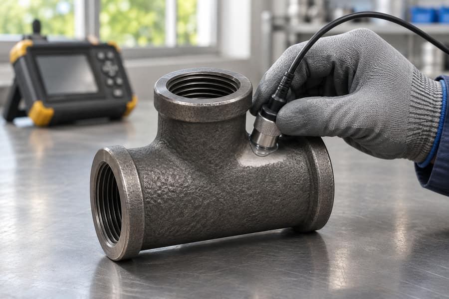
Ultrasonic thickness measurement may be suitable for accessible surfaces when the material and surface condition permit reliable readings. Calibration and measurement procedures must account for the instrument, material, and local geometry.
Irregular contours and curved surfaces can affect measurement reliability. Inspectors should consider probe positioning, surface preparation, coupling conditions, and instrument suitability when evaluating local readings.
Average thickness alone is insufficient when a local minimum controls design acceptance. A fitting may have an acceptable average while still containing a thinner region near the branch opening.
Inspection records should identify the measurement location and actual result. The recorded values can then be compared with the specified minimum finished-wall thickness and applicable dimensional tolerances.
Casting Defects Around Thick Junction Sections
The branch intersection may contain complex solidification conditions because several material sections meet within a relatively small area. Defects can develop when filling, feeding, or cooling is not adequately controlled.
Solidification voids:
A cavity can remain where the shrinking metal receives too little liquid feed. Thick junction regions and poorly designed feeding paths may increase the risk.
Internal porosity:
Gas-related or shrinkage-related discontinuities may occur within the casting. Their significance depends on location, size, distribution, material, and the applicable acceptance criteria.
Cracks and cold shuts:
Cracks can compromise structural continuity, while cold shuts may indicate incomplete fusion between metal fronts during mold filling. Both require evaluation against the specified inspection requirements.
An acceptable outer surface does not prove that the metal beneath it is sound. Suitable nondestructive examination methods should be selected according to material, geometry, defect concerns, and project requirements.
Acceptance criteria must be defined before inspection. A method may detect a discontinuity, but whether that indication is acceptable depends on the governing specification and the fitting’s intended service.
Pressure Testing and Final Acceptance
Hydrostatic testing can verify whether a fitting meets specified test conditions without showing unacceptable leakage. The test pressure, duration, medium, and acceptance requirements must follow the applicable design or project specification.
Testing should be performed using an established procedure and appropriate safety controls. The fitting must be properly prepared, and the test arrangement must account for the applicable pressure boundary and connection configuration.
A successful hydrostatic test does not replace dimensional verification, material identification, or structural design assessment. It demonstrates performance under the defined test conditions rather than establishing unrestricted suitability for other pressures or temperatures.
Final acceptance should bring together material documentation, dimensional results, wall thickness records, required nondestructive examination, and pressure test reports where applicable.
| Tee region | Main concern | Inspection priority |
| Main run | Pressure-containing wall and bore consistency | Wall thickness, diameter, and internal alignment |
| Branch neck | Local strength and connection integrity | Neck thickness, outside diameter, and end dimensions |
| Crotch | Stress concentration and internal discontinuities | Local thickness and appropriate internal examination |
| Heel | External material distribution and transition geometry | Wall thickness and surface condition |
| Branch opening | Passage dimensions and remaining surrounding material | Bore dimensions, alignment, and reinforcement geometry |
Engineering Drawing and Custom Cast Pipe Tee Requirements
Essential Branch Geometry Information
A complete engineering drawing gives the manufacturer a defined geometry to evaluate. It should distinguish nominal pipe sizes from actual finished dimensions and identify the required connection arrangement.
At a minimum, the drawing should communicate the following information:
- Main run dimensions: Nominal size, outside diameter, internal bore, and required wall thickness.
- Branch dimensions: Nominal size, outside diameter, internal bore, and branch neck length.
- Branch layout: Locate the off-take centerline and specify its angle and rotational position against the run datums.
- Junction geometry: Required crotch radius, heel contour, and relevant transition dimensions.
- Pipe-end definition: Specify the interface form, surfaces to machine, and permitted dimensional variation.
Drawings should also identify measurement datums and critical dimensions. Measurements taken from different datums can disagree even when inspectors examine the same tee.
Wall Thickness and Material Specifications
Material and wall requirements should be documented alongside the geometry. This allows the manufacturer to consider structural requirements and casting feasibility within the same design review.
- Material designation: Specify the required material type and grade rather than using a general description such as cast iron or cast steel.
- Design conditions: Provide design pressure, design temperature, and relevant fluid characteristics.
- Minimum thickness: Identify the minimum acceptable finished wall at critical regions, including the crotch and branch neck.
- Allowances: Define corrosion or erosion allowances where applicable, together with machining stock and casting tolerances.
- Design requirements: Identify the governing product specification, piping code, or documented qualification basis.
These details help prevent confusion between required finished thickness and nominal as-cast dimensions. They also provide a reference for reviewing core shift, machining removal, and dimensional variation.
Agreeing the Inspection Plan
Set the tee’s examination methods and acceptance limits before the foundry pours the first batch. The selected methods need to address the specific geometry, material, and risks associated with the application.
- Dimensional inspection: Define the critical diameters, center-to-end dimensions, branch angle, and geometric tolerances.
- Thickness verification: Identify measurement locations, methods, and minimum finished-wall requirements.
- Nondestructive examination: Specify applicable methods and acceptance criteria for relevant casting discontinuities.
- Pressure testing: Establish whether testing is required and identify the applicable procedure and acceptance conditions.
- Documentation: Define material traceability, inspection reports, and test records required for acceptance.
For ductile iron piping systems, the Ductile Iron Pipe Research Association distinguishes joint sealing from thrust restraint. A connection that prevents leakage does not automatically provide the mechanical restraint needed to resist pressure-induced forces.
This distinction matters when evaluating tee connections and external piping loads. Engineers should verify how thrust and other mechanical forces are transferred through joints, supports, restraints, and connected piping.
Custom Cast Pipe Tee Manufacturing Considerations at Boberry Machining
Boberry Machining offers custom metal pipe fittings, including tees, elbows, reducers, and connection fittings. Material and connection options are determined according to the specific order requirements.
Its gray cast iron category is described for non-pressurized drainage and venting applications. This product information should not be interpreted as establishing pressure ratings for all cast iron fittings or other material configurations.
For a custom cast tee, the initial technical inquiry should include the intended application, main run and branch dimensions, branch orientation, required wall thickness, material grade, and design conditions.
Engineering drawings should also identify the crotch and heel geometry, machining requirements, dimensional tolerances, and inspection expectations. These details provide the basis for reviewing the proposed configuration against its manufacturing and service requirements.