
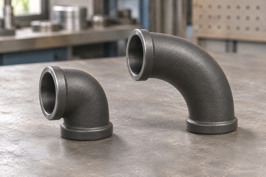
A cast pipe elbow redirects fluid through a curved passage. Its centerline bend radius changes the flow path and can influence velocity distribution, secondary motion, turbulence, and local pressure loss.
Choosing an elbow requires more than matching nominal pipe size: engineers must relate actual bore geometry to flow conditions, installation space, material, connection, and the fitting’s documented service limits.
Defining the Radius of a Cast Elbow
Locating the Three Radius Measurements
To measure centerline radius (CLR), start at the bend’s curvature center and measure outward to the middle of the bore. It describes how sharply the elbow redirects fluid and provides the primary geometric reference for comparing different bend configurations.
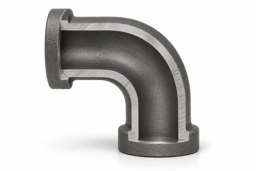
The inner radius and outer radius describe the boundaries of the curved passage. The inner radius follows the shorter path along the inside of the bend, while the outer radius follows the longer path along its outside surface.
For a symmetrical elbow with a consistent cross-section, the centerline radius lies between these two boundaries. Their relationship helps engineers understand the available flow area and identify whether the internal passage follows the intended geometry.
These dimensions should not be confused with the overall length or end-to-end dimensions of the fitting. Two elbows can have similar connection dimensions while following different curved paths and producing different hydraulic behavior.
Radius-to-Diameter Ratio (R/D)
The radius-to-diameter ratio provides a normalized way to compare elbow curvature across different pipe sizes. It is calculated by dividing the centerline bend radius by a defined reference diameter.
For hydraulic comparisons in this article, D means the actual internal diameter of the adjoining straight pipe, not its nominal pipe size or outside diameter. The calculation is therefore R/D = CLR / actual pipe internal diameter.
If the elbow’s internal bore differs from the adjoining pipe, both dimensions should be documented separately. The actual cross-sectional area at the selected reference section must also be used when calculating the corresponding flow velocity.
A smaller R/D represents a tighter bend relative to the pipe’s internal diameter. A larger R/D represents a more gradual curvature, although the ratio alone cannot establish the elbow’s complete hydraulic performance.
Short-radius and long-radius descriptions are useful when comparing product configurations, but their dimensional definitions must come from the applicable drawing or product specification. A supplier’s short-radius designation needs to be checked against its drawing.
When reviewing drawings, engineers should confirm the radius reference, internal diameter, elbow angle, and end dimensions together. This prevents a nominal radius designation from concealing differences in the actual flow passage.
How Bend Radius Changes Fluid Flow Inside an Elbow
Velocity Distribution and Secondary Flow
Fluid approaching an elbow generally travels along a relatively straight path. As the passage curves, the direction of motion changes, creating a radial pressure gradient across the cross-section.
The curved motion produces centrifugal effects that influence how fluid moves through the elbow. Higher pressure generally develops toward the outer side of the bend, while the inner region experiences a different pressure distribution.
Consequently, the velocity profile becomes less uniform than it would be in a sufficiently developed straight pipe. Fluid tends to redistribute across the passage instead of maintaining its original upstream velocity pattern.
Secondary flow develops when pressure gradients and viscous effects produce motion across the main flow direction. These cross-sectional movements can form paired circulation patterns that interact with the primary axial or directional flow.
Tighter curvature can intensify these disturbances. At comparable flow velocity and diameter, a tighter bend generally creates stronger curvature-related pressure gradients than a more gradual elbow.
However, the radius is not the only controlling variable. Reynolds number, elbow angle, upstream velocity distribution, surface condition, and internal geometry also influence the resulting flow field.
Flow Separation and Turbulence
Flow separation can occur when fluid near the wall cannot maintain its motion against an adverse pressure gradient. The boundary layer slows, loses momentum, and may detach from the internal surface.
Within a tight-radius elbow, the combination of curved flow and changing pressure distribution can increase the tendency for separation. The resulting recirculation regions disturb the main flow and contribute to additional energy dissipation.
Turbulence also affects the pressure distribution and velocity fluctuations inside the fitting. These effects become particularly important when the elbow operates at higher Reynolds numbers or receives an already disturbed inlet flow.
An extended-radius passage turns the stream over a longer curved path. This can reduce severe flow redistribution and separation under comparable operating conditions, although the actual improvement depends on the complete geometry.
Internal projections, uneven bore transitions, and casting irregularities can also disturb the boundary layer. A nominally large-radius elbow may therefore perform poorly if its actual passage contains significant geometric discontinuities.
The Influence of Flow Conditions
Reynolds number helps describe the relationship between inertial and viscous forces in a flowing fluid. It depends on fluid density, average velocity, characteristic diameter, and dynamic viscosity.
Different Reynolds number ranges produce different flow characteristics, so an elbow’s hydraulic behavior cannot be evaluated from radius alone. A configuration suitable for one operating condition may behave differently at another flow rate.
Velocity is particularly important because the kinetic energy associated with flow increases with the square of velocity. Consequently, even an unchanged elbow can produce substantially greater pressure loss when the operating velocity increases.
Viscosity affects the development of boundary layers and the relative importance of viscous forces. Temperature may change viscosity and density, meaning that the same piping arrangement can experience different hydraulic conditions during operation.
For liquids containing suspended particles, additional considerations include particle concentration, size, settling behavior, and possible accumulation near the inner bend. These factors may affect long-term flow area and maintenance requirements.
Engineers should therefore evaluate the elbow using representative operating conditions rather than relying exclusively on a geometric comparison. Flow rate, temperature, fluid properties, and upstream conditions belong in the hydraulic calculation.
How Bend Radius Affects Pressure Loss
Understanding the Elbow Pressure Loss Coefficient (K)
The local pressure loss coefficient, commonly represented by K, expresses the irreversible hydraulic loss associated with a fitting relative to a selected reference velocity. K gives a dimensionless basis for comparing fittings under the stated flow conditions.
The pressure-equivalent loss is calculated using the following relationship:
Δp_loss = K × ρV_ref² / 2
Here, Δp_loss represents irreversible pressure loss, K is the dimensionless local loss coefficient, ρ is fluid density, and V_ref is the average velocity at the specified reference section.
The velocity reference must be stated whenever a K value is reported or applied. A practical convention is to use the average velocity in the adjoining straight pipe, calculated from its actual internal diameter and the operating volumetric flow rate.
Where inlet and outlet diameters differ, or the elbow has a bore different from the connected pipe, the reference section and its corresponding velocity must be identified explicitly. Coefficients based on different velocity references cannot be compared directly without conversion.
The U.S. Department of Energy’s fluid-flow handbook describes local resistance through fitting loss coefficients and their relationship to flow velocity. This framework provides a useful basis for evaluating elbows alongside valves and other piping components.
K depends on more than the centerline radius. Important variables include elbow angle, R/D, Reynolds number, internal roughness, cross-sectional consistency, and the velocity profile approaching the fitting.
Engineers should use published or experimentally established coefficients only when their geometry, flow conditions, and reference-velocity conventions are sufficiently comparable. A value from a different elbow configuration should not automatically be transferred to a custom casting.
Short-Radius vs. Long-Radius Elbows: Pressure Loss Differences
Short-radius elbows redirect fluid over a more compact curved path. The sharper curvature can increase secondary flow, pressure redistribution, and separation, often producing greater local resistance than a comparable larger-radius configuration.
Long-radius elbows provide a more gradual directional change. Under otherwise comparable conditions, this geometry often reduces curvature-related disturbances and can produce a lower local loss coefficient.
However, the comparison must use consistent conditions. Pipe internal diameter, elbow angle, flow rate, fluid properties, surface condition, and inlet velocity profile should remain comparable when evaluating the influence of bend radius.
A larger radius also increases the length of the curved passage. For a given elbow angle, the fluid travels a longer distance along the bend, potentially increasing distributed wall-friction losses.
This creates an important engineering tradeoff. A larger radius may reduce local separation-related losses while adding passage length and installation space requirements. The total pressure-loss difference depends on how these effects combine.
For this reason, engineers should avoid assuming that the largest available radius always provides the lowest overall system resistance. The appropriate design depends on the actual fitting geometry and the method used to calculate its hydraulic loss.
The distinction between local and distributed losses is especially important. If a published K coefficient represents the complete measured loss through the elbow, adding a separate friction calculation for the same curved passage may count part of the resistance twice.
Equivalent Length and Cumulative Piping Pressure Loss
The equivalent-length method expresses a fitting’s resistance as the length of straight pipe that would produce an equivalent friction loss under the same reference conditions. It helps engineers combine fittings and straight-pipe sections in one calculation.
For a Darcy friction factor, the relationship is commonly expressed as Le/D = K/f_D, provided that K and the straight-pipe friction calculation use the same reference velocity and diameter convention.
The equivalent length is not an independent physical dimension of the elbow. It depends on the selected friction factor, which changes with Reynolds number, relative roughness, and the applicable flow regime.
Engineers must also distinguish between Darcy and Fanning friction factors. Check which friction-factor convention the reference uses: converting a Fanning value to a Darcy value requires multiplication by four.
Using the Darcy-Weisbach formulation, straight-pipe friction loss is expressed as Δp_f = f_D × (L/D) × (ρV²/2). With the Fanning factor, the equivalent expression includes 4f_F instead of f_D.
Mixing these conventions produces an incorrect pressure-loss calculation even when the underlying measurements are accurate. Calculation sheets should identify which friction-factor definition is being used.
Multiple elbows can contribute substantially to the total resistance of a piping network. Their individual losses should be evaluated together with straight-pipe friction, valves, reducers, tees, and other components.
The U.S. Department of Energy’s local-loss framework is useful for this system-level assessment. It helps engineers distinguish fitting resistance from distributed pipe friction instead of treating every pressure change as an elbow-specific loss.
Ultimately, the calculated system resistance affects pump head requirements and operating energy. Selecting an elbow based on its individual geometry without considering the entire piping arrangement can therefore produce an incomplete design decision.
An elbow loss estimate needs the following geometric and operating inputs.
| Factor | Influence on pressure loss | Engineering consideration |
| Bend radius | Changes curvature and secondary flow intensity | Specify centerline radius and actual-bore R/D |
| Elbow angle | Determines the overall directional change | Confirm the required angle and geometry |
| Internal diameter | Determines flow area and reference velocity | Verify actual bore dimensions |
| Surface condition | Influences wall friction and local disturbances | Define relevant internal surface requirements |
| Flow conditions | Influence Reynolds number and hydraulic behavior | Specify flow rate, density, and viscosity |
| Inlet flow profile | Changes the flow entering the curved passage | Review upstream fittings and available straight length |
Other Geometric Factors That Influence Elbow Flow Performance
Internal Bore and Cross-Sectional Consistency
The actual internal diameter determines the available flow area and therefore affects average fluid velocity. Even when two elbows share the same nominal pipe size, differences in their internal passages can produce different hydraulic behavior.
A smaller bore increases velocity at a constant volumetric flow rate. Because the local pressure-loss relationship includes velocity squared, relatively modest changes in flow area can have meaningful consequences for pressure-loss calculations.
Casting processes can introduce variations associated with core positioning, dimensional control, and internal surface formation. These variations may change the passage geometry even when external dimensions remain within their specified tolerances.
Engineers should review the minimum and maximum internal dimensions where they affect flow capacity. A single nominal diameter may not adequately describe a passage with noticeable taper, offset, or cross-sectional variation.
Internal transitions between the adjoining pipe and elbow also deserve attention. Abrupt changes in area can introduce additional local resistance that should not be attributed entirely to the centerline bend radius.
Casting Surface Condition and Internal Irregularities
Internal surface roughness contributes to frictional resistance, particularly where the flow passage is long enough for distributed wall effects to become significant. Its influence depends on Reynolds number and relative roughness rather than surface appearance alone.
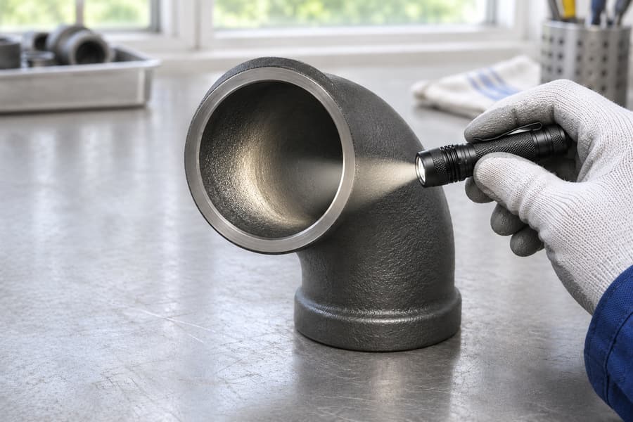
Cast surfaces may contain irregularities such as uneven transitions, projections, or localized depressions. Their hydraulic importance depends on their size, position, and relationship to the overall internal passage.
Ordinary surface texture should be distinguished from defects that compromise the specified wall geometry or product integrity. Not every visible surface variation produces a meaningful pressure-loss increase.
Inspection requirements should therefore reflect the intended service. Where hydraulic performance is critical, internal bore inspection and dimensional verification may be more informative than relying only on external appearance.
Surface finishing should also be specified according to practical requirements. Removing unnecessary internal projections may improve passage consistency, but additional finishing should not be assumed to create a particular K value without supporting evaluation.
Elbow Angle and Installation Alignment
Elbow angle determines the degree of directional change. A 45-degree elbow redirects flow less than a 90-degree elbow, but the resulting resistance cannot be established from angle alone.
The bend radius, cross-sectional profile, internal finish, and operating conditions remain important. Two elbows with the same angle can have different pressure-loss characteristics when their geometry or manufacturing quality differs.
Connection alignment also affects the transition between the adjoining pipe and the elbow. An internal step, offset, or abrupt diameter change may disturb the incoming flow and create additional turbulence.
Adjacent components can influence the velocity profile entering an elbow. A reducer or valve placed immediately upstream may produce a nonuniform flow distribution that changes the behavior of the downstream fitting.
Hydraulic Institute guidance on reducer orientation in pump piping illustrates why nearby transitions should be considered as part of the overall layout. Such guidance does not establish a universal correction factor for every elbow arrangement.
Where an elbow is installed near a pump or another flow-sensitive component, engineers should assess the available straight-pipe length and upstream disturbances. An isolated fitting coefficient may not represent the complete installed configuration.
Material and Standards Considerations for Cast Pipe Elbows
Differences Between Cast Iron and Cast Steel
Material selection affects the mechanical suitability and service limitations of a cast elbow, but it does not independently determine its hydraulic resistance. Internal diameter, bend geometry, and surface condition remain the primary geometric variables.
Gray cast iron:
Its graphite-flake structure gives the material different mechanical behavior from ductile iron and cast steel. Gray cast iron products intended for non-pressurized drainage or venting should not be assumed suitable for pressurized service.
Ductile iron:
Rounded graphite nodules make this iron more capable of tensile deformation than typical flake-graphite gray iron. Pressure-service suitability nevertheless depends on the specified grade, fitting design, manufacturing requirements, and applicable product documentation.
Malleable iron:
This material is produced through heat treatment of cast iron and is used in certain fitting applications, including threaded configurations. The selected grade must meet the elbow specification and the loads expected in service.
Cast steel:
Cast steel has a different composition and mechanical-property framework from the cast iron families. Specify the steel grade and service envelope, then define the casting acceptance and examination requirements.
Matching outside dimensions says nothing about whether one casting material can replace another. Engineers must confirm the material designation and verify that the selected product is appropriate for the fluid and operating environment.
Applicable Standards and Pressure Rating Verification
Standards must be selected according to fitting construction, material, connection type, and intended application. A standard covering one manufacturing category cannot automatically establish compliance for a product made through another process.
ASME B16.9 covers factory-made wrought buttwelding fittings, while ASME B16.11 addresses forged fittings. Neither standard establishes a cast fitting’s pressure rating merely because its dimensions resemble a standardized product.
ASME B16.3, for example, addresses malleable iron threaded fittings. Its material and connection scope should not be generalized to cast steel, ductile iron, or other fitting configurations without checking the applicable requirements.
Buyers should identify the governing product specification and confirm its relationship to the fitting’s material and manufacturing method. Dimensional compatibility is useful for installation, but it is not proof of standard compliance.
Pressure rating also requires separate attention. The allowable service pressure depends on factors such as material grade, design geometry, temperature, manufacturing requirements, and the applicable product specification.
Hydraulic pressure loss and allowable pressure rating describe different engineering properties. The former represents irreversible energy loss during flow, while the latter concerns the fitting’s permitted pressure-service conditions.
A fitting may produce relatively low hydraulic resistance without having a verified pressure rating for the intended application. Conversely, a pressure-rated fitting can still create undesirable system losses if its geometry is unsuitable.
Design pressure and temperature should be evaluated rather than relying only on ordinary operating readings. Pressure surges, temperature changes, and other service conditions may affect the required design basis.
How to Select the Appropriate Bend Radius for a Piping System
Balance Pressure Loss and Installation Space
The first selection step is to establish the required flow rate, fluid properties, and acceptable pressure-loss allowance. These values provide the operating basis for comparing alternative elbow geometries.
A larger-radius elbow may reduce curvature-related flow disturbances, but its longer curved path and larger installation envelope require additional space. This can affect equipment clearance, pipe routing, structural support, and maintenance access.
A tighter-radius configuration may be appropriate where the available installation space is limited. However, its potentially greater hydraulic resistance should be included in the total system calculation rather than ignored for convenience.
Engineers should compare alternatives using consistent internal diameters, flow conditions, and pressure-loss methods. Where reliable K values are unavailable for a custom geometry, additional hydraulic evaluation or representative testing may be necessary.
The selection should balance hydraulic efficiency against physical constraints. Maximizing radius without considering layout can create unnecessary installation difficulties without providing a proportionate improvement in system performance.
Evaluate Hydraulic and Mechanical Requirements Together
Hydraulic calculations establish whether the elbow geometry can meet flow and pressure-loss requirements. Mechanical evaluation separately establishes whether the fitting is suitable for its intended pressure, temperature, material, and installation conditions.
Actual internal diameter, wall geometry, connection dimensions, and material grade should be checked against the project specification. External dimensional compatibility alone does not confirm that the internal passage or pressure-service requirements are satisfied.
Connection design also requires attention to sealing and mechanical restraint. For ductile iron pressure piping, guidance from the Ductile Iron Pipe Research Association distinguishes joint sealing from thrust restraint.
A joint that prevents leakage does not automatically demonstrate that the elbow is restrained against pressure-induced movement. Where the connection arrangement requires separate restraint, the system design must address the relevant hydraulic thrust loads.
Engineers should also review the combined resistance of nearby fittings and valves. Selecting a lower-loss elbow provides limited system benefit if other components create substantially greater resistance or disturb the incoming flow.
The final decision should therefore use two separate checks: hydraulic performance for the intended flow conditions and documented mechanical suitability for the specified service. Neither check should substitute for the other.
What to Specify When Ordering Custom Cast Pipe Elbows
Essential Dimensional and Geometric Information
A complete dimensional specification helps ensure that the proposed casting matches the piping layout and provides the intended internal flow passage. Drawings should define both connection geometry and the curved section.
- Nominal pipe size: Identify the connected pipe size and provide its actual internal diameter where hydraulic calculations depend on it.
- Elbow angle: State the required directional change and any project-specific angular tolerances.
- Centerline radius: Specify the required CLR and identify the radius reference used on the drawing.
- Internal bore: Provide the required internal diameter and identify any permitted transitions or dimensional variations.
- End dimensions: Define center-to-end or end-to-end dimensions, as well as the relevant connection interfaces.
- Wall thickness: Specify the required wall geometry and applicable dimensional tolerances according to the design requirements.
- Surface requirements: Identify relevant internal surface conditions, finishing requirements, and inspection criteria.
Where pressure loss is a major design concern, the drawing should make the actual internal passage clear. An external profile alone may not reveal the bore transitions that influence hydraulic performance.
Material and Operating Requirements
Material information should identify the required family and grade rather than simply stating that the fitting must be cast iron or steel. The specification should also identify the applicable product standard where one governs the design.
Operating information provides the context for evaluating both material suitability and hydraulic performance. Normal flow conditions should be distinguished from the more demanding design conditions used for mechanical verification.
- Material: Identify gray cast iron, ductile iron, malleable iron, or cast steel, together with the required grade.
- Fluid: Describe the fluid composition and any relevant compatibility or contamination considerations.
- Temperature: State the expected operating and design temperatures.
- Pressure: Provide operating pressure, design pressure, and relevant transient conditions where applicable.
- Flow rate: Specify the required volumetric or mass flow rate and the operating range.
- Connection: Identify threaded, flanged, or other required connection configurations and interface dimensions.
- Verification: Define applicable inspection, testing, material documentation, and acceptance requirements.
Where a target pressure-loss coefficient or maximum pressure drop is required, the calculation basis should also be documented. This includes the reference velocity, actual internal diameter, fluid properties, and operating condition.
Providing these details allows the fitting geometry to be assessed against the actual piping application. It also reduces ambiguity when comparing proposed dimensions, materials, and connection arrangements.
Custom Metal Pipe Fitting Options from Boberry Machining
Boberry Machining offers custom metal pipe fittings, including elbows, tees, reducers, and connection fittings. Confirm the chosen alloy and end configuration when reviewing the order drawing.
For a custom cast pipe elbow inquiry, buyers should provide the dimensional drawing, centerline radius, elbow angle, internal bore, material requirements, and connection details. Operating pressure, temperature, and flow conditions provide additional context for technical evaluation.
Pressure-service suitability must be confirmed against the selected material, product specification, and documented design requirements. A custom fitting’s dimensional similarity to a wrought or forged standard should never be treated as automatic evidence of compliance.
A useful inquiry package should also identify the allowable hydraulic pressure loss, the reference diameter used in R/D calculations, and any required internal inspection criteria. These details help distinguish geometric requirements from performance and acceptance requirements.
With the drawing, material designation, connection specification, and operating conditions clearly defined, the proposed elbow can be evaluated against the actual installation and service requirements rather than nominal dimensions alone.