
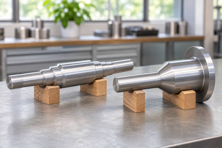
Roll forging forms heated stock through longitudinal passes between profiled roll segments, progressively redistributing material along the workpiece. Open die forging shapes heated stock through repeated pressing or hammering between relatively simple dies, with manipulators repositioning the workpiece between operations.
Their suitability depends less on a ranking than on profile geometry, equipment limits, tooling investment, production mix, and finished-part requirements.
What Are Roll Forging and Open Die Forging?
Although both processes shape metal through compressive deformation, their tooling arrangements and workpiece movements create different manufacturing possibilities. The drawing should reveal whether a fixed roll profile can shape the stock or whether successive local compressions offer a more workable route.
Roll Forging Process
Roll forging is a metal forming process that uses opposing, powered rolls fitted with profiled segments to deform heated bars or billets longitudinally.
The workpiece passes between the rotating rolls, where matching profiles progressively reduce selected cross-sections and redistribute material along its length. Successive passes develop the required longitudinal shape.
The main characteristics include:
- Progressive deformation: Material changes shape through successive roll engagements rather than one complete forming stroke.
- Profile-controlled forming: Roll grooves determine how material is redistributed across different longitudinal sections.
- Repeated positioning: The workpiece must enter the rolls in the intended orientation and follow the planned pass sequence.
- Elongated geometry: The process commonly produces tapered sections, stepped profiles, and preforms with changing cross-sections.
Roll forging can serve as a primary forming operation or prepare stock for subsequent forging. Its suitability depends on whether the required profile can be developed through the available roll configuration.
Open Die Forging Process
Open die forging uses relatively simple dies, commonly flat or shaped tooling, to deform heated metal through repeated pressing or hammering operations.
Unlike profiled roll segments, open dies do not continuously impose a predetermined longitudinal contour. Operators control the resulting shape by adjusting workpiece position, orientation, and deformation sequence.
Typical operations include:
- Drawing out: Reducing cross-sectional dimensions while increasing workpiece length.
- Upsetting: Increasing cross-sectional dimensions by compressing the workpiece along its axis.
- Cogging: Applying successive compressive strokes to progressively reduce and reshape the stock.
- Rotating and repositioning: Changing the workpiece orientation to develop the required dimensions around its circumference.
Manipulators support workpiece movement and positioning between forging operations. The operator coordinates handling with press or hammer movements to achieve the intended dimensional changes.
This arrangement accommodates varied component dimensions and forging sequences, although complex profiles may require additional operations and subsequent machining.
Key Differences Between Roll Forging and Open Die Forging
The two processes differ in several practical areas, including forming principles, tooling configuration, equipment requirements, and production suitability. Read the comparison below alongside the part drawing, paying particular attention to section changes and the operations that follow forging.
| Comparison Factor | Roll Forging | Open Die Forging |
| Forming method | Longitudinal rolling between profiled rolls | Incremental pressing or hammering |
| Tooling | Profiled roll segments | Relatively simple dies |
| Material movement | Guided through successive roll passes | Controlled through repeated deformation and repositioning |
| Typical geometry | Elongated, tapered, stepped profiles | Shafts, blocks, solid sections, and varied shapes |
| Equipment | Powered rolling equipment | Hydraulic presses or forging hammers |
| Workpiece handling | Guided entry and pass positioning | Manipulator-assisted handling |
| Flexibility | Depends on roll profiles and pass design | Depends on die arrangement and forging sequence |
| Production suitability | Repeated, compatible profiles | Varied components and flexible forging requirements |
| Machining | Depends on profile accuracy and surface condition | Depends on forged dimensions and required final geometry |
Component Geometry and Suitable Applications
Component geometry is one of the most important factors when selecting between roll forging and open die forging. The location, length, and magnitude of cross-sectional changes influence how efficiently each process can form the workpiece.
Geometries Suited to Roll Forging
Roll forging is particularly relevant when material must be redistributed along an elongated component to create a defined longitudinal profile.
Typical geometry characteristics include:
- Tapered sections: Gradual reductions in cross-sectional dimensions along the component length.
- Stepped profiles: Different sections arranged along one longitudinal axis.
- Changing cross-sections: Transitions between larger and smaller sections that can be developed through successive roll passes.
- Repeated profiles: Components requiring consistent geometry across multiple production orders.
For example, a tapered shaft blank may require a larger section near one end and a progressively reduced section toward the other. Roll forging can develop this distribution through appropriately designed roll profiles.
However, the feasibility depends on transition geometry, material volume, deformation requirements, and the available tooling arrangement. Abrupt changes or complicated features may require additional forming or machining operations.
Roll forging is also used to prepare preforms for subsequent operations. In these cases, the objective is to distribute material appropriately before the component enters another forging or finishing stage.
Geometries Suited to Open Die Forging
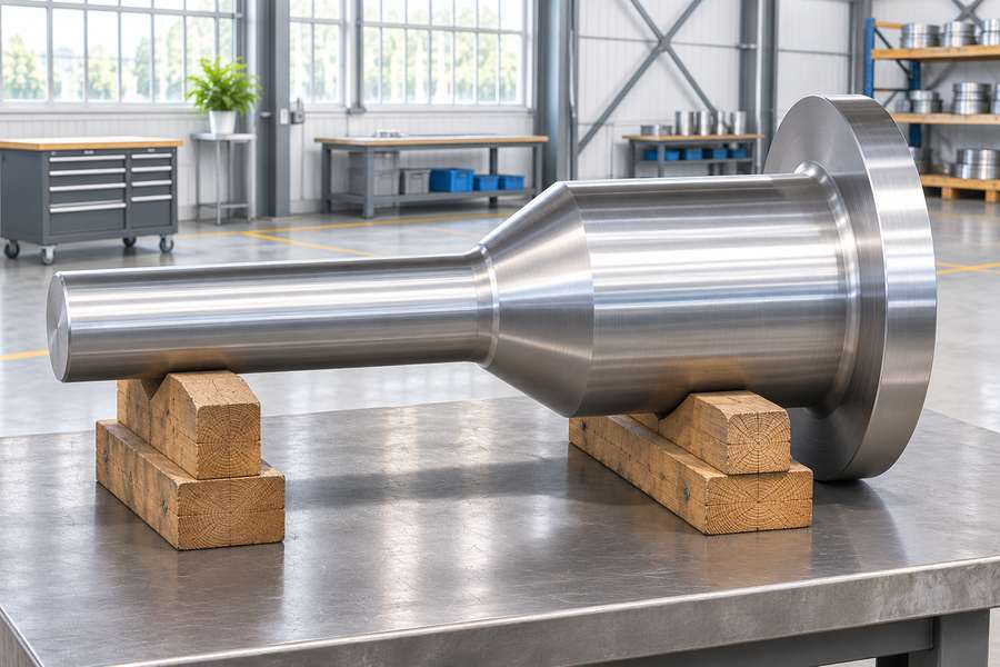
Open die forging is suitable for components whose dimensions can be developed through controlled compression and workpiece repositioning.
Common examples include:
- Long shafts: Cylindrical or stepped components requiring longitudinal deformation.
- Solid blocks: Rectangular or other solid sections developed through repeated compression.
- Large forgings: Components requiring substantial material movement and flexible deformation sequences.
- Variable sections: Parts with dimensional changes that can be developed through different forging operations.
- Custom-shaped blanks: Forgings intended for extensive machining into more complex finished components.
A large shaft, for example, may require drawing out, upsetting, or localized deformation to achieve its specified forged dimensions. The sequence depends on the drawing and material requirements.
Open die forging does not automatically reproduce every finished-part feature. Shoulders, grooves, complex transitions, and precision surfaces may need to be created through machining.
Evaluating Geometry Beyond Overall Dimensions
Overall length and diameter alone do not establish process suitability. Buyers should also examine the relationship between adjacent sections, local material distribution, and the final machining requirements.
Several drawing details deserve particular attention:
- Section transitions: Determine whether dimensional changes are gradual or involve abrupt shoulders.
- Cross-sectional shape: Identify round, square, rectangular, or other required sections.
- Material distribution: Check whether sufficient stock exists in each region for the intended forming sequence.
- Machining accessibility: Consider whether the forged shape allows subsequent cutting and inspection.
- Reference features: Identify critical datums and surfaces that must remain suitable for final machining.
A component with a straightforward longitudinal profile may be suitable for roll forging, while a part requiring varied section development may benefit from open die forging.
The decision should follow the complete geometry and manufacturing requirements, not simply the apparent similarity between the finished component and a typical forged shape.
Equipment Requirements and Practical Limitations
Equipment configuration establishes the practical boundaries of both processes. Buyers should evaluate not only the forming machine but also tooling dimensions, workpiece handling, heating arrangements, and the sequence required to complete the forging.
Roll Forging Equipment
Roll forging equipment uses powered rolls fitted with matching profiled segments. Their geometry, rotational arrangement, and forming capability determine which workpiece profiles can be developed.
Important equipment considerations include:
- Roll dimensions: Roll diameter, working width, and available profile space influence the geometry that can be accommodated.
- Forming capability: Available force and drive characteristics must support the intended material deformation.
- Tooling configuration: Roll grooves and pass arrangements must correspond to the required material distribution.
- Workpiece feeding: The stock must enter the rolls in the correct position and orientation.
- Pass coordination: Successive operations must develop the profile without creating unsuitable transitions or deformation conditions.
A component may appear geometrically suitable for roll forging but remain impractical if its required profile exceeds the available tooling configuration.
The feasibility assessment should therefore include the complete roll arrangement rather than relying only on the machine’s nominal dimensions.
Open Die Forging Equipment
Open die forging commonly uses hydraulic presses or forging hammers. Both apply compressive deformation, but their operating characteristics and process-control requirements differ.
Hydraulic presses apply controlled compressive force through the press stroke. Their suitability depends on available force, working dimensions, deformation requirements, and the material being forged.
Forging hammers deliver repeated impact energy to deform the workpiece. Their application depends on hammer energy, operating sequence, workpiece response, and the required deformation.
Additional equipment also influences practical feasibility:
- Anvils and dies: Their working surfaces and dimensions determine the available contact arrangement.
- Manipulators: These handle, rotate, and reposition the workpiece between forging operations.
- Heating equipment: Appropriate heating arrangements support the required forging temperature throughout the sequence.
- Handling systems: Cranes and supporting equipment help move stock between heating, forging, and subsequent operations.
Manipulator capacity deserves particular attention because the workpiece must remain controllable throughout the forming sequence. Its weight, length, temperature, and required orientation all influence handling arrangements.
Tooling Investment, Production Flexibility, and Cost
Tooling investment is an important difference between roll forging and open die forging. However, tooling cost alone does not determine which process offers better manufacturing economics.
The complete assessment should include preparation, production setup, workpiece handling, material utilization, machining, and inspection. Each operation contributes to the cost of an accepted finished component.
Tooling Requirements and Initial Investment
Roll forging requires profiled roll segments designed around the intended component geometry. Their profiles must accommodate material distribution, section transitions, and the planned sequence of deformation.
Tooling development may involve several considerations:
- Profile design: Roll grooves must correspond to the required longitudinal cross-sections.
- Tooling preparation: Manufacturing and preparing profiled segments contributes to initial investment.
- Process setup: Roll positioning and pass arrangements must support consistent forming conditions.
- Design changes: Revised component dimensions may require tooling modifications or a different configuration.
Open die forging generally uses less profile-specific tooling. Relatively simple dies can support different workpiece dimensions through changes in positioning and forging sequences.
However, simpler tooling does not eliminate setup costs. Operators must still establish suitable deformation sequences, heating arrangements, handling procedures, and dimensional controls.
Production Flexibility and Order Requirements
Roll forging becomes more attractive when a component has a repeatable longitudinal profile and production requirements justify dedicated tooling.
Once the tooling arrangement is established, repeated production can follow a defined sequence. This supports consistency when the material, geometry, and process conditions remain appropriately controlled.
Open die forging offers greater flexibility when product dimensions or order requirements vary. The same general tooling arrangement may accommodate different components, although each requires its own process assessment.
Consider these purchasing situations:
- Repeat orders: A consistent profile may justify investment in dedicated roll tooling.
- Custom components: Open die forging may accommodate changing dimensions without developing an entirely new profiled roll arrangement.
- Design revisions: Roll forging may require tooling adjustments, while open die forging may allow changes through revised forming sequences.
- Mixed production: Open die forging can be practical when the product range involves different shapes and dimensions.
Neither process has a universal production-volume advantage. The appropriate choice depends on the relationship between tooling investment, order repetition, and total manufacturing effort.
Comparing Total Manufacturing Cost
A meaningful cost comparison should evaluate the complete route rather than the initial forging operation alone.
Roll forging may involve greater initial tooling preparation but potentially reduce repeated forming and handling requirements for compatible profiles. Open die forging may reduce profile-specific tooling investment but require additional manipulation or machining.
Buyers should examine the following cost elements:
- Material consumption: Starting stock dimensions, deformation losses, and machining allowances.
- Tooling: Initial preparation, modifications, maintenance, and expected reuse.
- Production operations: Heating, forming, handling, and setup requirements.
- Machining: Material removal needed to achieve finished dimensions and surface conditions.
- Inspection: Dimensional checks, mechanical testing, and documentation requirements.
Any saving on dies can be offset by extra handling, reheating, cutting time, or inspection work later in the route. The comparison should use the same material specification, finished geometry, acceptance criteria, and delivery scope.
Material Flow, Process Control, and Forging Quality
Material flow differs between roll forging and open die forging because their deformation methods impose different contact conditions and forming sequences.
Understanding these differences helps buyers evaluate process qualification, material distribution, and the controls needed to achieve acceptable forged components.
Material Flow During Roll Forging
In roll forging, profiled segments apply pressure to selected regions as the workpiece advances through successive passes. Material moves away from compressed regions and redistributes along the longitudinal profile.
The roll arrangement determines where deformation occurs and how the cross-section changes. Poorly coordinated transitions can create material distribution problems or sections that do not match the intended profile.
Important considerations include:
- Profile transitions: Adjacent sections must allow practical material redistribution during forming.
- Pass sequence: Successive reductions should support the intended deformation rather than concentrate excessive changes in one operation.
- Material temperature: The workpiece must remain within an appropriate forging temperature range for the selected material.
- Alignment: Incorrect positioning can affect the resulting profile and dimensional consistency.
Roll forging can influence grain-flow direction through longitudinal deformation. However, the resulting structure depends on the material, deformation history, temperature, and subsequent heat treatment.
Material Flow During Open Die Forging
Open die forging develops material distribution through successive compressive operations. Drawing out, upsetting, and rotating the workpiece allow different regions to receive deformation.
The sequence matters because deformation must reach the intended sections without creating unsuitable transitions or leaving insufficient stock for subsequent machining.
For components such as forged shafts
, the manufacturing plan may need to consider axial deformation, cross-sectional changes, and material distribution along the component.
The operator must coordinate the forging sequence with workpiece handling. Manipulator positioning, deformation location, and temperature conditions all influence the resulting shape.
Process Control and Quality Qualification
Neither forming method automatically guarantees superior mechanical properties or freedom from defects. Quality depends on the complete manufacturing route and whether its controls satisfy the material specification and component requirements.
Important process controls include:
- Heating control: Monitor the heating and temperature conditions appropriate to the material.
- Deformation planning: Establish suitable reductions, pass sequences, or forging strokes.
- Workpiece handling: Maintain appropriate positioning and orientation during forming.
- Cooling control: Consider the cooling route and its influence on the resulting material condition.
- Heat treatment: Specify the required treatment according to material grade, section dimensions, and mechanical property requirements.
Potential quality concerns include surface cracking, laps, unsuitable material distribution, and internal discontinuities. Their occurrence and significance depend on material condition and process execution.
Inspection should follow the actual component risks and acceptance requirements. Visual examination, dimensional inspection, mechanical testing, and appropriate nondestructive examination may form part of the qualification plan.
Buyers should also specify where mechanical properties must be verified. Test locations and specimen orientation matter because results from one section may not represent every region of a component.
Machining Allowance and Final Component Accuracy
Forged components commonly require machining before reaching their final dimensions. Consequently, buyers must evaluate the relationship between the forged envelope, machining allowance, and finished-part tolerances.
Choose the retained stock after reviewing the expected forged envelope, alloy behavior, surface cleanup, and planned finishing cuts. Neither roll forging nor open die forging has one universally applicable machining allowance.
Establishing Machining Allowances
Roll forging may produce a relatively defined longitudinal profile, but the resulting dimensions still require verification against the machining plan.
Open die forgings may require machining stock across several surfaces because their final geometry develops through incremental deformation and workpiece repositioning.
When determining allowances, consider:
- Surface removal: Provide sufficient stock to remove the expected forged surface condition.
- Dimensional variation: Account for variation between the forged envelope and finished dimensions.
- Section transitions: Check that shoulders and tapered regions retain adequate material for machining.
- Stock distribution: Avoid allocating excessive material to some regions while leaving insufficient stock elsewhere.
- Machining sequence: Coordinate the allowance with the order of rough machining and finishing operations.
A drawing should distinguish forged dimensions from finished dimensions. Without this distinction, the supplier and buyer may interpret the required machining stock differently.
Dimensional Accuracy and Inspection
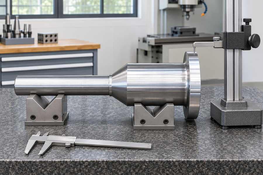
Final accuracy depends on both forging and machining. A suitable forging shape can reduce unnecessary material removal, but finished-part compliance must be established through the specified inspection process.
Buyers should identify critical features, including:
- Straightness: Important for long components and shaft-like geometries.
- Concentricity and runout: Relevant when multiple cylindrical sections share a common rotational reference.
- Shoulder locations: Important when axial dimensions control assembly relationships.
- Surface condition: Specify requirements for machined and unmachined regions separately.
- Reference datums: Establish how critical dimensions should be measured and related to one another.
Inspection planning should also distinguish intermediate forged dimensions from final machined dimensions. Measurements taken before machining cannot independently establish finished-part acceptance.
For components with multiple diameter changes, checking dimensions at several axial locations can help identify uneven material distribution and potential machining problems.
The inspection method, measurement locations, and acceptance criteria should be agreed before production. This reduces disagreements about whether dimensional variation is acceptable at different manufacturing stages.
Process Selection and Drawing Review for Engineering Buyers
Selecting between roll forging and open die forging requires a combined assessment of geometry, material, equipment suitability, order quantity, and finished-part requirements.
A process that appears attractive during initial forming may become less economical after tooling, machining, inspection, and handling requirements are considered.
Evaluating Component Requirements
Start with the component drawing rather than selecting a process based on general industry applications.
For roll forging, examine whether the longitudinal profile can be developed using a practical profiled roll arrangement. Repeated section transitions and consistent geometry may support this route.
For open die forging, examine whether incremental deformation and manipulator handling can achieve the required forged envelope. This route may be more adaptable when dimensions and forming sequences vary.
Several decision factors deserve particular attention:
- Geometry: Identify component length, cross-sections, tapered regions, and dimensional transitions.
- Material: Confirm the grade, applicable material specification, and required mechanical properties.
- Equipment: Check forming capability, tooling dimensions, and workpiece handling requirements.
- Quantity: Evaluate initial order size, repeat orders, and expected design changes.
- Machining: Establish the finished dimensions, critical surfaces, and required stock.
- Inspection: Identify dimensional checks, mechanical tests, and nondestructive examination requirements.
These factors should be considered together. A repeatable profile does not automatically justify roll tooling if the equipment arrangement cannot accommodate the component.
Similarly, open die forging is not automatically preferable simply because its tooling is less profile-specific.
Practical Drawing and RFQ Checklist
Before requesting a manufacturing assessment, buyers should prepare sufficient technical information for a meaningful comparison.
Table 2. Buyer Decision Checklist for Forging Process Selection
| Evaluation Item | Information to Confirm | Selection Impact |
| Component geometry | Length, cross-sections, tapers, and transitions | Determines forming suitability |
| Material specification | Grade, standard, and material condition | Influences process qualification |
| Dimensions | Forged envelope and finished dimensions | Establishes equipment and machining requirements |
| Order quantity | Initial quantity and expected repeat demand | Affects tooling economics |
| Mechanical properties | Required strength, toughness, and test conditions | Determines process and heat treatment controls |
| Machining allowance | Stock requirements and critical surfaces | Influences material consumption |
| Inspection | Dimensional checks, testing, and acceptance criteria | Establishes quality verification requirements |
| Delivery requirements | Required manufacturing stages and documentation | Supports production planning |
The RFQ should clearly distinguish mandatory requirements from preferences. For example, a buyer may specify a required finished dimension while allowing the supplier to evaluate alternative forging routes.
Drawings should also identify any features that cannot be changed without approval. These may include critical dimensions, material requirements, machining datums, and specified mechanical properties.
Discussing Manufacturing Requirements with Boberry Machining
A useful manufacturing discussion begins with complete technical information rather than a request for a general price comparison.
Provide Boberry Machining with the component drawing, material grade, required quantity, and finished-part specifications. Include any available information about operating conditions and mechanical property requirements.
The discussion should cover:
- Forging geometry: Confirm the intended forged shape and section transitions.
- Manufacturing route: Evaluate whether roll forging or open die forging is suitable for the component.
- Equipment constraints: Identify relevant forming, tooling, and handling limitations.
- Machining requirements: Clarify allowances, datums, finished dimensions, and critical surfaces.
- Quality acceptance: Define heat treatment, testing, inspection methods, and documentation.
- Commercial scope: Confirm quantities, repeat-order expectations, delivery requirements, and included manufacturing operations.
A clear drawing review allows the proposed manufacturing route to be evaluated against the actual component requirements, including tooling investment, machining needs, inspection expectations, and finished-part acceptance.