
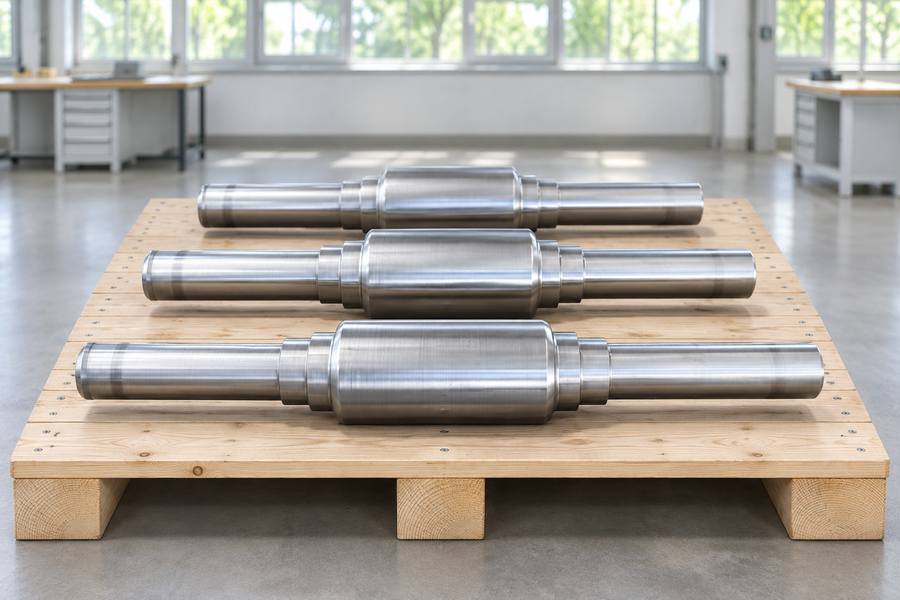
Cross wedge rolling shapes a rotating billet between opposed wedge tools. In flat-die systems, the dies travel linearly; in roll-type systems, profiled rolls rotate and engage the billet.
Longitudinal roll forging instead feeds the billet axially through opposed profiled roll segments, progressively changing selected sections to form an elongated preform for later forging or machining.
What Are Cross Wedge Rolling and Longitudinal Roll Forging?
Cross wedge rolling: wedge tools and billet rotation
Cross wedge rolling reduces selected billet sections with wedge-shaped tools while the workpiece rotates and advances. The wedge profile controls metal displacement and changes the section along the billet.
In flat-die cross wedge rolling, opposed dies carry wedge profiles and move along a linear path. Their movement makes the billet rotate and advance; the dies themselves do not rotate.
In roll-type cross wedge rolling, wedge profiles are mounted on rotating rolls that engage the heated billet. Billet rotation and axial movement remain central to producing the axisymmetric preform.
Longitudinal roll forging: axial feed through profiled rolls
Longitudinal roll forging feeds a billet lengthwise through opposed profiled roll segments. The grooves progressively compress selected regions and change the cross-section as the billet translates through the roll gap.
Several grooves or passes may develop the preform. The defining motion is longitudinal billet feed through the roll segments, not rotation around its own axis.
The distinction matters because both processes may use rotating tools. Roll-type cross wedge rolling uses rotating wedge profiles, but billet rotation is fundamental; longitudinal roll forging relies on axial feed and successive groove engagement.
Buyers should request a clear description of the proposed machine arrangement and pass sequence. The term roll forging can cover different practices, so the quotation should identify the actual forming route.
Component Shapes and Typical Preforming Applications
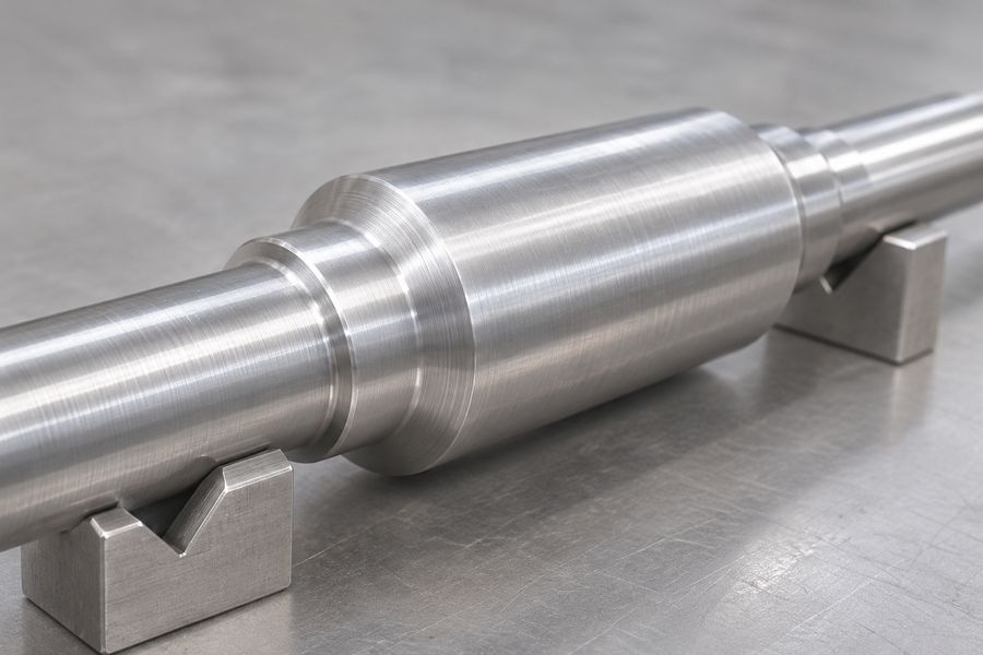
Shapes suited to cross wedge rolling
Cross wedge rolling is commonly considered for components with rotationally symmetric geometry along a longitudinal axis. It can create a sequence of diameters, tapers, and enlarged sections in shaft-like preforms.
Typical candidates include stepped shafts, axles, pins, and other elongated axisymmetric parts. These shapes often contain localized diameter changes that can be formed through wedge-controlled deformation before later forging or machining.
Non-axisymmetric features usually require additional operations. Flats, cross-holes, keyways, splines, and detailed interfaces may need downstream die forging or machining rather than direct formation during wedge rolling.
For shaft projects, compare the preform with the intended forged shafts route. The key question is whether its section changes suit the proposed process.
Shapes suited to longitudinal roll forging
Longitudinal roll forging redistributes a billet along its length to create an elongated preform with changing sections. Roll grooves establish local thickness, width, and cross-sectional transitions.
Possible preforms include tapered bars, stepped blanks, and elongated sections prepared for subsequent impression-die forging. The required groove sequence depends on the billet dimensions, material response, and deformation assigned to each pass.
The process can place material near regions that require larger sections in the finished component. However, deep recesses, transverse holes, intricate webs, and close-tolerance interfaces commonly remain downstream forging or machining features.
Assess the roll forging process as one manufacturing stage. A suitable-looking preform may still create handling, die-filling, or machining difficulties later.
Geometry-led selection
Cross wedge rolling is generally more naturally matched to rotationally symmetric diameter sequences. Longitudinal roll forging is more naturally assessed for lengthwise section changes produced through successive profiled roll engagements.
Neither description replaces drawing review. Overall length, section ratios, transition radii, local volume requirements, material grade, and downstream die geometry can all change the process decision.
Material Flow and Deformation Characteristics
Material displacement in cross wedge rolling
In cross wedge rolling, wedge contact progressively reduces selected billet zones. Metal flows toward adjacent sections and along the billet, producing axial elongation as the workpiece rotates through the forming region.
Wedge angle, reduction sequence, contact conditions, and billet temperature influence deformation. Abrupt section changes or poorly coordinated reductions can concentrate strain, distort the profile, or increase defect risks.
Because the billet rotates, the tools engage material around its circumference. This action supports axisymmetric sections, while billet tracking, rotation, and consistent tool engagement remain important to dimensional control.
Material displacement in longitudinal roll forging
In longitudinal roll forging, the billet advances through the roll gap as profiled rolls compress selected regions. Metal moves into adjacent sections and along the length, changing the cross-section through successive grooves.
Groove geometry, pass reduction, friction, temperature, and initial billet dimensions influence material distribution. The pass sequence must avoid demanding excessive deformation or leaving material unevenly distributed for downstream operations.
Abrupt transitions or unsuitable reductions may encourage laps, folds, uneven profile formation, or local underfilling. These risks should be considered during groove design and confirmed through appropriate process inspection.
Grain flow and mechanical properties
Both processes plastically deform metal and can influence grain orientation. The resulting flow pattern depends on stock condition, temperature history, deformation path, and subsequent heat treatment.
Neither route guarantees superior strength. Mechanical performance also depends on material cleanliness, defect control, reduction, grain direction relative to service loads, heat treatment, and final geometry.
For loaded shafts, consider material flow relative to bending and torsional stresses, especially around shoulders. Specify material condition, heat treatment, test locations, and acceptance requirements for critical properties.
Tooling Investment and Production Economics
Tooling configuration and design
Cross wedge rolling uses wedge tooling matched to the required section sequence. Flat-die systems use shaped profiles on opposed dies; roll-type systems carry wedge geometry on rotating tools.
Longitudinal roll forging uses profiled roll grooves or segments to create successive cross-sectional changes. Its design must coordinate groove geometry, billet feed, pass reductions, and the material volume required at each location.
Tooling cannot be estimated reliably from the finished outline alone. The review should establish:
- Starting stock: billet dimensions and material grade.
- Preform definition: target sections, transitions, and stock distribution.
- Production basis: quantity, downstream operations, and inspection scope.
Investment, maintenance, and amortization
Initial tooling cost may include engineering review, profile development, tool manufacture, setup, trials, and revisions. Every extra forming stage adds another profile to develop, check, manufacture, and align with the preceding operation.
Maintenance depends on tooling geometry, contact conditions, material, temperature, and production practice. Buyers should clarify inspection, repair, storage, wear monitoring, and responsibility for maintenance rather than assume a fixed tool life.
Amortization depends on acceptable parts produced during tool life. Dedicated tooling may suit stable repeat demand but become less attractive with small orders or frequent design changes.
The quotation should state whether tooling is charged separately or included in the part price. It should also clarify ownership, storage, maintenance responsibility, and the basis for charging later modifications.
Production volume and material utilization
The economics depend on the complete route, not just rolling speed. Billet preparation, heating, handling, downstream forging, heat treatment, machining, inspection, and rejected parts all affect cost per accepted component.
Cross wedge rolling may reduce machining from uniform stock, while longitudinal roll forging may redistribute material before later forging. Actual material utilization depends on billet size, end losses, preform geometry, machining allowance, and scrap.
Compare the material input with the accepted finished part, including cut-off losses and rejected preforms. A reduction in one region may require extra stock elsewhere, so apparent savings should be checked against the full route.
Production volume changes the balance between tooling and piece cost. Larger repeat orders can spread dedicated tooling expense across more parts, while short or irregular orders place greater weight on setup and tooling flexibility.
A fair quotation should use the same scope for both processes. It should identify tooling, material, forming, secondary operations, inspection, scrap assumptions, and delivery condition so that excluded operations do not distort the comparison.
Process Limitations, Potential Defects, and Inspection
Geometry and Process Limitations
Cross wedge rolling is most suitable when the required preform has rotational symmetry and a sequence of axial diameter changes. Complex transverse features usually need another operation.
Flat-die and roll-type arrangements also impose different tooling and handling constraints. Billet length, starting diameter, section transitions, and the required reduction must suit the selected arrangement.
Longitudinal roll forging is suited to elongated preforms whose cross-section changes along the feed direction. Its practical limits depend on groove design, pass sequence, billet support, and material response to deformation.
Neither process should be selected from a two-dimensional outline alone. Deep shoulders, abrupt transitions, thin sections, hollow regions, and uneven volume distribution may complicate forming or require secondary operations.
Potential Defects and Their Causes
Cross wedge rolling requires stable billet rotation and controlled axial movement. Slipping can produce an incorrect cross-section, while unsuitable reductions may contribute to necking, surface laps, or internal cracking.
Tool contact can also leave spiral marks or local surface damage. End cavities and dimensional variation should be considered where billet ends, tool engagement, or material flow affect the finished preform.
In longitudinal roll forging, poor groove matching or an unsuitable pass sequence can cause uneven section development. Material may fold at transitions, twist during feeding, or fail to fill the intended profile.
Excessive local deformation, unsuitable forming temperature, or inconsistent billet dimensions can increase defect risks in either route. These are process-dependent risks, not defects that should be assumed in every rolled part.
Inspection and Acceptance Planning
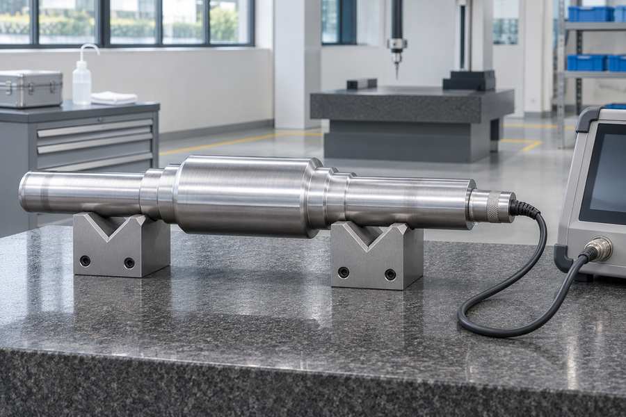
Inspection should follow the component’s function and the risks associated with its forming route. A general visual check is useful, but it cannot establish internal soundness or verify every critical dimension.
- Visual examination: Check for surface laps, folds, cracks, scale-related damage, and abnormal tool marks.
- Dimensional measurement: Record critical diameters, widths, lengths, shoulders, transition locations, and overall profile.
- Section checks: Measure at defined axial positions and, where relevant, multiple angular positions to identify uneven deformation or ovality.
- Nondestructive testing: Specify ultrasonic, magnetic-particle, or liquid-penetrant examination when appropriate to the material, geometry, defect concern, and acceptance standard.
- Destructive verification: Where required, use sectioning, macro examination, or mechanical testing to evaluate internal structure and material properties.
Assign each measurement or examination to a specific point in the production sequence. A preform measurement may reveal a forming issue before downstream forging, while final inspection verifies the dimensions and condition that matter to the buyer.
Acceptance documents should state the applicable material specification, heat-treatment condition, test location, sampling basis, and rejection criteria. Replace vague inspection promises with named methods, coverage, sampling rules, and acceptance limits.
Comparing the Complete Manufacturing Routes
From Billet Preparation to Finished Component
The two processes should be compared as complete production routes rather than isolated forming operations. Their economic and technical value depends on what happens before and after rolling.
A cross wedge rolling route generally begins with material verification, billet cutting, and heating. The billet then enters flat-die or roll-type wedge tooling, where rotation and axial movement develop the required axisymmetric preform.
After rolling, the part may require cooling under controlled conditions, end trimming, straightening, heat treatment, machining, and inspection. If the rolled shape is a preform, it may proceed to press forging before final finishing.
A longitudinal roll forging route also begins with material verification, billet preparation, and heating. The billet travels through opposed profiled roll segments, often through successive grooves that distribute material along its length.
The rolled preform may then be transferred to a forging press for final shaping, followed by trimming, heat treatment, machining, and inspection. Depending on the component design, some operations may be unnecessary, while others become essential to achieve the specified geometry.
When a preform is intended for closed-die forging, its volume distribution and transition geometry should be assessed against the downstream die cavity. A preform that is easy to roll is not automatically suitable for filling the final impression.
Side-by-Side Process Comparison
| Comparison factor | Cross wedge rolling | Longitudinal roll forging |
| Main billet movement | Rotates and advances through wedge engagement | Translates lengthwise through opposed profiled rolls |
| Tool arrangement | Flat wedge dies or profiled wedge rolls | Opposed rolls with shaped grooves or segments |
| Typical geometry | Axisymmetric stepped or tapered preforms | Elongated preforms with changing cross-sections |
| Material distribution | Radial reduction with axial elongation | Progressive section reduction and longitudinal redistribution |
| Common preforming role | Shaft-like blanks and axisymmetric press-forging preforms | Elongated blanks for subsequent forging |
| Main design focus | Stable rotation, wedge geometry, reduction, and axial flow | Groove sequence, pass reduction, feed, and section transitions |
| Potential concerns | Slip, necking, laps, internal cracking, and profile variation | Folds, uneven sections, twisting, and dimensional variation |
| Downstream route | Further forging or machining, as specified | Further forging or machining, as specified |
The table describes typical process tendencies, not universal rules. Actual suitability depends on the machine arrangement, material, component geometry, production plan, and acceptance requirements.
A route comparison should include transfer and reheating needs, intermediate handling, material losses, tool maintenance, and inspection. A lower forming cost can be offset by extra finishing or a difficult downstream operation.
How to Select the Right Process for Your Project
Match the Process to Geometry and Material
Use the finished dimensions to determine the stock envelope needed before machining and subsequent forming. Identify which regions need more material, which sections can be reduced, and where final machining or die filling controls the design.
For axisymmetric stepped components, evaluate whether cross wedge rolling can create the diameter sequence without introducing difficult transitions. For elongated sectional preforms, examine whether longitudinal roll forging can distribute material through a practical series of roll passes.
Material grade and starting condition also matter. Hot workability, deformation resistance, billet dimensions, and temperature control influence the forming plan, while heat treatment determines properties after deformation.
Evaluate the Complete Order Requirements
Production quantity should be considered alongside tooling complexity and design stability. A repeat order with a stable drawing may justify dedicated tooling differently from a prototype or frequently revised component.
Compare quotations on a consistent basis. Include billet material, cutting, heating, rolling, tooling, secondary forging, heat treatment, machining, inspection, packaging, and expected scrap treatment.
Do not compare a rolled preform price with a finished-part price. Confirm whether each quotation covers the same delivery condition, machining allowance, testing, documentation, and acceptance criteria.
Buyer Decision Checkpoints
| Decision factor | Buyer checkpoint |
| Component geometry | Confirm critical sections, transitions, datums, and tolerances. |
| Material | State the grade, governing specification, starting condition, and substitution limits. |
| Order profile | Provide prototype quantity, batch size, annual demand, and likely revisions. |
| Tooling | Clarify tooling charges, ownership, maintenance, and expected production volume. |
| Quality | Define inspection methods, test locations, sampling, traceability, and acceptance criteria. |
| Final processing | Identify preform condition, heat treatment, machining allowance, and remaining operations. |
Drawing Review and RFQ Preparation
A useful request for quotation gives the manufacturing reviewer enough information to assess both the forming route and the finished component. Attach the approved drawing revision so shoulder positions, tolerances, and other requirements remain unambiguous.
When discussing a project with Boberry Machining, ask for the proposed manufacturing sequence and the assumptions behind the process selection. Clarify whether the recommendation concerns a rolled preform, a forging blank, or a machined component.
The review should identify unresolved drawing details before tooling decisions are made. Critical dimensions, material condition, inspection scope, and downstream interfaces should be agreed in the RFQ or technical clarification record.
Where both processes appear feasible, request a route comparison using the same finished-part requirements and production assumptions. This makes differences in tooling, material utilization, secondary operations, and inspection visible before the order is placed.