
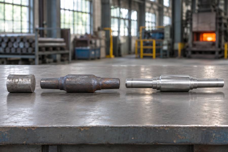
Here, roll forging means longitudinal roll forging: heated bar stock is shaped between opposed rotating rolls with profiled grooves. Each groove reshapes a chosen length of stock, creating the next preform profile.
It is used to produce elongated preforms, including stepped shaft forms, when geometry, material, tooling, and machining requirements suit the process.
What Is Longitudinal Roll Forging?
Longitudinal roll forging is a metal forming process that uses two opposed rotating rolls equipped with specially shaped die segments. The grooves progressively deform heated metal stock as it moves through the forming area.
The rolls squeeze the billet into a new profile; they do not cut that profile from the stock. Selected sections become smaller or change shape while material flows toward adjacent regions.
The process is particularly relevant to elongated components with varying cross-sections. Typical examples include stepped shafts, tapered sections, and forged preforms that require additional machining.
Working Principle of Longitudinal Roll Forging
The working principle depends on the interaction between roll rotation, groove geometry, workpiece movement, and material temperature.
- Opposed rotating rolls: Two rolls rotate in opposite directions, drawing the heated workpiece into the forming zone.
- Profiled die grooves: Shaped grooves contact the stock and apply compressive forces to selected sections.
- Progressive deformation: Successive groove engagements reduce or reshape specific cross-sectional areas.
- Longitudinal material flow: Metal moves along the workpiece as its cross-section changes.
- Controlled forming sequence: The arrangement of grooves determines how the component develops from its initial billet geometry.
The exact deformation pattern depends on die design, billet dimensions, material properties, and the intended component profile. These factors must be considered together during process planning.
How Does Longitudinal Roll Forging Differ from Other Rolling Processes?
Longitudinal roll forging, cross wedge rolling, and ring rolling all use rolling forces to deform metal, but their tooling arrangements and manufacturing objectives differ.
Understanding these distinctions helps engineers identify the appropriate process before developing tooling or requesting quotations.
Longitudinal Roll Forging
Longitudinal roll forging uses opposed rotating rolls with profiled grooves to progressively shape heated stock along its length.
The workpiece advances through the forming zone, and successive groove engagements create changes in its longitudinal cross-sectional profile. This approach is suitable for evaluating stepped shafts and elongated forged preforms.
Cross Wedge Rolling
Cross wedge rolling uses wedge-shaped tooling to reduce or redistribute material along an axisymmetric workpiece.
The wedges move relative to the billet and generate localized deformation as the material rotates and advances through the forming zone. The resulting geometry can include stepped diameters and other rotationally symmetrical features.
Although both processes can produce elongated components, their tooling arrangements and deformation paths are different.
Ring Rolling
Ring rolling starts with a preformed ring blank rather than a long bar billet. Rolling tools reduce the ring wall while increasing its diameter.
The process primarily develops annular components, with radial and axial dimensions controlled through the rolling arrangement.
Ring rolling is therefore intended for a different component geometry from longitudinal roll forging.
Key Differences in Manufacturing Objectives
| Process | Tooling Configuration | Workpiece Geometry | Primary Manufacturing Objective |
| Longitudinal roll forging | Opposed rotating rolls with profiled grooves | Heated elongated stock | Produce stepped or varying-section longitudinal profiles |
| Cross wedge rolling | Wedge-shaped forming tools | Cylindrical billets or stock | Form axisymmetric components through localized deformation |
| Ring rolling | Radial and axial rolling tools | Preformed ring blanks | Increase ring diameter while controlling wall dimensions |
The selection should follow the component drawing rather than similarities in the general use of rolling forces. Geometry, material flow, tooling investment, and downstream machining determine which route deserves consideration.
Step-by-Step Longitudinal Roll Forging Manufacturing Process
Longitudinal roll forging involves several connected manufacturing stages. Each stage influences the next, from initial material selection to final dimensional acceptance.
The following sequence explains how engineers and manufacturers typically organize the process. Specific equipment arrangements and operations depend on the component design and production route.
Review Engineering Drawings and Component Requirements
Manufacturing planning begins with a detailed review of the component drawing. Engineers identify the overall length, diameter changes, shoulder positions, tapered sections, and other important geometric features.
The drawing review should distinguish between as-forged dimensions and finished machining dimensions. This distinction establishes the material allowance needed for subsequent operations.
Important information includes:
- Overall component dimensions and sectional profiles.
- Material grade and applicable material requirements.
- Critical shoulders, journals, transitions, and functional surfaces.
- Required machining allowances.
- Dimensional and geometric acceptance criteria.
- Heat-treatment and inspection requirements.
Engineers also evaluate whether the profile can be generated through the available groove arrangement. Abrupt section changes, narrow transitions, and complex geometries may require alternative forming sequences.
At this stage, the manufacturing route should account for the complete component rather than considering the forging operation independently.
Select Materials and Plan Billet Dimensions
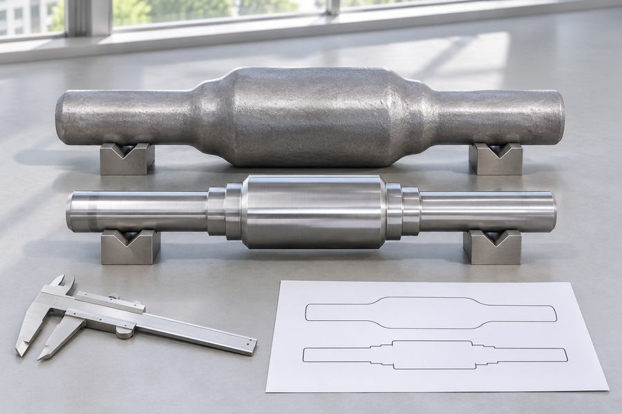
Material selection affects deformation behavior, heating requirements, and subsequent mechanical properties. Carbon steel, alloy steel, and other suitable forging materials may be considered according to component requirements.
The starting billet must contain enough material to produce the required forged profile and accommodate planned finishing operations.
Billet planning generally considers:
- Material grade: Confirm the specified composition and material condition.
- Starting diameter: Select stock dimensions appropriate for the largest required section.
- Billet length: Calculate the material needed for the complete longitudinal profile.
- Material allowance: Account for machining stock and manufacturing losses.
- Deformation behavior: Consider how the selected material responds to hot working.
The material volume can be estimated from the intended component geometry, but the initial billet calculation must also consider scale formation, end cropping, and process-specific material losses.
A suitable billet plan reduces unnecessary material consumption while providing enough stock for forming and finishing.
Cut and Prepare the Billet
After selecting the starting material, the stock is cut into individual billets according to the production plan.
Cutting methods should produce consistent billet lengths and suitable end conditions. Significant differences between billets can affect positioning and the amount of material available during forming.
Preparation includes several checks:
- Verify material identification against the order requirements.
- Check the billet surface for visible cracks, seams, or other unacceptable conditions.
- Confirm the cut length and starting dimensions.
- Remove surface contamination where necessary.
- Separate and identify prepared billets to maintain material traceability.
Surface defects deserve attention because heating and deformation may make existing discontinuities more difficult to assess later.
The prepared billet is then transferred to the heating stage according to the planned manufacturing sequence.
Heat the Billet to the Required Forging Temperature
Heating increases metal plasticity, allowing the billet to undergo substantial deformation under compressive forces.
Select the heating window for the specified alloy and stock size, then check it against the planned pass sequence. A heating setting that works for one billet may be unsuitable for another.
Check the following aspects of the heating plan.
- Heating uniformity: The billet should reach a suitable temperature throughout the section being formed.
- Material limitations: Excessive heating can cause oxidation, grain growth, or other metallurgical problems.
- Transfer time: Delays between heating and forming can reduce the available working temperature.
Temperature differences between the billet surface and interior may also influence deformation behavior. Larger sections generally require careful consideration of heating uniformity.
The heating procedure should therefore follow the material specification and approved process requirements rather than an assumed universal setting.
Prepare the Rolls and Install Shaped Die Segments
While the billet is being prepared, the forming equipment and roll tooling must be configured for the intended profile.
The die segments contain grooves that progressively shape the workpiece. Their geometry determines where deformation occurs and how material moves between adjacent sections.
Tooling preparation involves:
- Reviewing groove profiles against the component drawing.
- Checking die condition and working surfaces.
- Confirming roll alignment and the intended forming arrangement.
- Verifying the relationship between successive groove stages.
- Checking that the planned workpiece dimensions are compatible with the tooling.
The sequence of groove profiles deserves particular attention. An unsuitable reduction sequence can concentrate deformation in one region or create irregular transitions.
Tooling design should also consider the material’s response to deformation and the finishing allowance required after forging.
Position the Billet and Begin the Initial Rolling Pass
Once the billet reaches the required forming condition, it is positioned between the rotating rolls.
The rolls engage the workpiece through their shaped grooves. Their rotation and groove arrangement guide the stock into the forming zone and begin reducing the selected section.
The initial pass establishes the starting deformation pattern. Operators and process controls must account for billet positioning, engagement, and the relationship between the stock and tooling.
Important points include:
- Correct billet orientation before engagement.
- Stable feeding into the working area.
- Appropriate contact between the stock and groove surfaces.
- Consistent positioning relative to the intended profile.
- Observation of the initial deformation pattern.
Incorrect positioning can produce uneven section changes or an irregular starting profile. These problems may carry into later forming stages.
The initial pass should therefore be evaluated before proceeding through the remaining groove sequence.
Complete Successive Rolling Passes
After the initial deformation, the workpiece progresses through the remaining forming stages. Each groove applies a specific deformation according to the planned profile.
As the selected sections become smaller, metal flows toward adjacent regions according to the groove geometry and deformation conditions. This material redistribution helps develop the intended longitudinal profile.
The workpiece may pass through several grooves, with each stage producing a different cross-sectional change. Early stages establish the general shape, while later stages refine individual diameters, transitions, and shoulders.
The forming sequence should avoid concentrating excessive deformation in one location. Abrupt reductions can increase forming resistance and create unfavorable material flow, depending on the material and tooling arrangement.
Engineers evaluate the following factors when developing the pass sequence:
- Reduction distribution: Divide the required deformation among suitable forming stages.
- Groove geometry: Match each groove to the intended cross-sectional change.
- Material flow: Allow metal to move into adjacent sections without creating unwanted folds.
- Workpiece alignment: Maintain the intended relationship between the billet and forming grooves.
- Profile development: Check that intermediate shapes provide sufficient material for subsequent stages.
The number and arrangement of passes depend on the starting billet, material grade, final geometry, and tooling design. A complicated shaft profile may require a different sequence from a component with only a few diameter changes.
Control Deformation and Intermediate Heating
Temperature and deformation must remain coordinated throughout the forming sequence. As the workpiece passes through successive grooves, it loses heat through contact with tooling and exposure to the surrounding environment.
If the material temperature falls outside the suitable working range, its resistance to deformation may increase. This can affect forming consistency and create additional demands on the tooling.
Process planning should consider:
- Temperature monitoring: Check whether the workpiece remains within the approved forming range.
- Pass timing: Coordinate successive operations to limit unnecessary delays.
- Deformation distribution: Avoid excessive reduction in individual stages.
- Intermediate reheating: Consider reheating when the remaining operations require it and the material procedure permits it.
- Surface condition: Monitor oxidation and other changes that may influence subsequent processing.
Intermediate heating is not automatically necessary for every component. Its use depends on the material, billet dimensions, forming sequence, and temperature conditions.
The objective is to complete the intended deformation without exposing the material to unsuitable thermal or mechanical conditions.
Complete the Forming Operation and Verify the Profile
After the final planned pass, the workpiece should have the approximate geometry required for subsequent manufacturing operations.
The forged profile is checked against the intended intermediate dimensions and overall shape. This evaluation identifies obvious forming deviations before the component moves into finishing.
Depending on the component design, verification may include:
- Overall length and major section dimensions.
- Diameter changes along the workpiece.
- Shoulder locations and transition geometry.
- Straightness and visible bending.
- Surface condition and apparent forming irregularities.
The as-forged component does not necessarily meet the finished drawing dimensions. Its purpose is to provide the required material distribution and machining stock for later operations.
If the profile contains significant deviations, engineers should investigate the billet preparation, groove arrangement, alignment, and forming conditions rather than relying on machining to correct every problem.
Cooling and Removing Excess Material
Once forming is complete, the component proceeds through the specified cooling procedure. Cooling conditions depend on the material grade, section dimensions, and subsequent heat-treatment requirements.
Uncontrolled cooling can contribute to dimensional distortion or an unsuitable metallurgical condition. The cooling route should therefore follow the approved manufacturing procedure.
The next operations may include:
- Removing excess end material through cropping.
- Removing scale and loose surface deposits.
- Performing straightening when required and technically appropriate.
- Checking the overall forged profile before further processing.
- Identifying the component for subsequent manufacturing stages.
Cropping is particularly relevant when the billet ends contain material that cannot be incorporated into the finished component.
Straightening should be evaluated carefully because additional deformation may influence residual stresses and dimensional stability.
Perform Heat Treatment and Surface Preparation
Heat treatment may be required to establish the mechanical properties and material condition specified for the component.
The appropriate procedure depends on the material family, component section, intended application, and applicable technical requirements.
For carbon and alloy steels, possible heat-treatment routes include normalizing, annealing, and quenching and tempering. The selected route should reflect the required properties and material specification.
Stainless steels require grade-specific consideration. Austenitic stainless steels, for example, do not respond to conventional quenching and tempering in the same way as hardenable alloy steels.
Establish the Required Heat-Treatment Condition
The heat-treatment plan should identify the intended condition before production begins. This avoids treating heat treatment as an optional finishing operation added without reference to the component specification.
Important considerations include:
- Material grade: Confirm the heat-treatment response of the selected material.
- Section dimensions: Consider how component thickness affects heating and cooling behavior.
- Required properties: Identify the specified hardness and mechanical-property requirements.
- Furnace procedure: Follow an appropriate documented treatment cycle.
- Inspection location: Establish where hardness or mechanical-property testing must be performed.
Different sections of a forged shaft may respond differently because of their dimensions and cooling characteristics. Consequently, testing locations and acceptance requirements should be agreed before manufacturing.
Heat treatment cannot correct every forging defect. Cracks, laps, and other material discontinuities require separate evaluation and should not be assumed to disappear during thermal processing.
Clean and Prepare the Surface
After the specified thermal operations, the component may require surface cleaning before machining or inspection.
Scale removal and other preparation methods should suit the material and the next manufacturing operation.
Surface preparation may involve:
- Removing oxide scale and loose deposits.
- Cleaning surfaces before dimensional measurement.
- Preparing areas for nondestructive testing where applicable.
- Identifying surface conditions that require additional investigation.
- Protecting the component against contamination during handling.
A clean surface makes visual examination and subsequent machining more practical. However, cleaning does not replace inspection for cracks or other discontinuities.
Machine Critical Features
Roll forging produces a near-net or intermediate profile rather than necessarily delivering a finished component. Finishing cuts bring journals, shoulders, and other specified surfaces into the dimensional limits on the approved drawing.
For forged shafts, machining may involve turning, facing, drilling, boring, or other operations depending on the component design.
Establish Machining Allowances
Machining allowance is the additional material retained on the forged component for removal during finishing.
The allowance must accommodate the actual as-forged profile, expected dimensional variation, and the required finished surface condition.
Engineers should distinguish between:
- As-forged dimensions: Measurements taken before machining.
- Machining allowance: Material intentionally retained for finishing.
- Finished dimensions: Dimensions required by the final engineering drawing.
- Geometric requirements: Straightness, concentricity, runout, and other specified controls.
An allowance that is too small may leave insufficient material to achieve complete surface cleanup. Leaving unnecessary stock means more cutting passes and more chips for each finished component.
The appropriate value depends on the component geometry, forming process, material, and machining plan. It should be established through drawing review and manufacturing assessment rather than a universal allowance table.
Machine Functional Surfaces and Features
Machining focuses on the areas that determine assembly, movement, positioning, or load transfer.
For a stepped shaft, these may include bearing journals, shoulders, coupling interfaces, and specified diameter transitions.
The machining sequence should consider how the component is supported and referenced during processing. Suitable datum selection helps maintain dimensional relationships between different sections.
Typical machining considerations include:
- Establishing reference surfaces and center locations.
- Maintaining relationships between multiple shaft diameters.
- Producing specified shoulder positions and lengths.
- Machining keyways, grooves, or threaded features when required.
- Checking surface finish against drawing requirements.
Not every roll-forged component requires the same machining operations. Some designs need only limited finishing, while others require substantial material removal to achieve their final geometry.
Conduct Final Quality Inspection
Final inspection verifies whether the manufactured component meets the agreed drawing, material, and quality requirements.
Inspection should cover both dimensional characteristics and material condition. A component that matches its nominal dimensions may still require additional evaluation if its application includes specific mechanical or internal-quality requirements.
Dimensional and Geometric Inspection
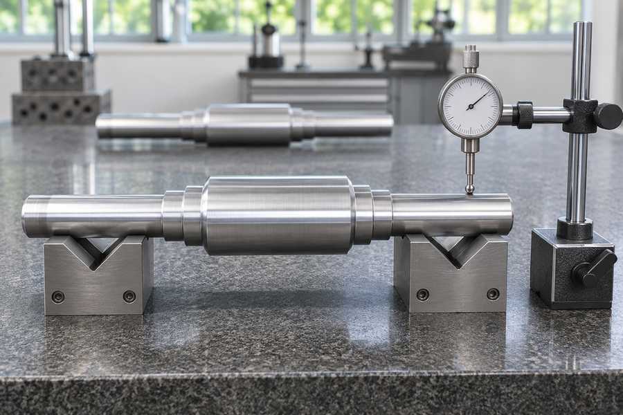
Dimensional inspection compares measured results with the specified drawing requirements.
Depending on component geometry, measurements may include:
- Overall length and individual section lengths.
- Shaft diameters at specified locations.
- Shoulder positions and transition dimensions.
- Straightness and concentricity where specified.
- Surface roughness on designated functional areas.
Measurements should use suitable instruments and clearly defined reference points. For long components, the support arrangement can influence readings, particularly when checking straightness or runout.
Inspectors should also distinguish between measurements taken before and after machining. This prevents as-forged dimensions from being incorrectly evaluated against finished-part tolerances.
Material and Surface Inspection
Material verification confirms that the component corresponds to the ordered material specification and required processing condition.
Depending on the purchase requirements, inspection may include:
- Material identification and traceability.
- Chemical composition documentation.
- Hardness testing.
- Mechanical-property testing.
- Visual surface examination.
- Applicable nondestructive testing.
Ultrasonic testing, magnetic particle testing, or penetrant testing may be considered where appropriate for the material, component geometry, and acceptance requirements.
Each method has different detection capabilities and limitations. The inspection plan should identify the required method, examination area, acceptance criteria, and documentation.
Common Roll Forging Defects and Process Controls
Defect prevention begins during material preparation and tooling design. Inspection then verifies whether the controls produced an acceptable component.
Use the defect examples below to connect an observed problem with the checks that can help investigate it.
| Potential Defect | Possible Causes | Prevention and Inspection |
| Surface cracks | Unsuitable forming temperature, excessive deformation, or existing material defects | Control heating and deformation; perform visual or specified surface testing |
| Laps and folds | Improper material flow, unsuitable groove transitions, or unfavorable pass sequencing | Review groove geometry and pass distribution; examine critical surface areas |
| Incomplete profile formation | Insufficient deformation or unsuitable tooling configuration | Verify billet dimensions, groove design, and intermediate profile measurements |
| Dimensional variation | Inconsistent billet preparation, temperature changes, or tooling wear | Monitor starting stock, process conditions, and finished dimensions |
| Bending or distortion | Uneven deformation, handling, or cooling conditions | Review forming alignment, cooling procedures, and straightness measurements |
| Internal discontinuities | Existing material imperfections or unfavorable material conditions | Apply appropriate material examination and specified nondestructive testing |
These are possible manufacturing concerns rather than defects that occur in every roll forging operation. Their likelihood depends on the material, process design, and production controls.
Inspection findings should also be connected to manufacturing records. When a deviation appears, reviewing the relevant billet, tooling, heating, and forming information helps determine its likely origin.
Engineering and Purchasing Considerations for Roll Forged Components
A clear purchasing specification helps manufacturers evaluate feasibility, prepare tooling, and establish inspection requirements before production.
Buyers should provide enough technical information to distinguish the intended finished component from its intermediate forged profile.
Drawing and Material Specifications
The engineering drawing should show all important dimensions and geometric features. Where necessary, buyers should also provide a separate forging drawing indicating the intended as-forged profile.
State the alloy designation together with its governing specification and the condition in which the material must be supplied.
Procurement documentation should clarify:
- Finished component drawings and revisions.
- Material grade and specification.
- Required production quantity.
- Applicable heat-treatment condition.
- Critical dimensional and geometric features.
- Special surface or testing requirements.
If certain dimensions are intended for machining rather than direct acceptance in the forged state, this distinction should be communicated clearly.
Dimensional Tolerances and Machining Allowances
Buyers should identify which dimensions apply before machining and which apply to the finished component.
This is particularly important for stepped shafts, where several diameter sections may require different finishing operations.
The specification should clarify the required machining stock, critical datums, and dimensional acceptance criteria. Buyers should also identify any dimensions that require closer inspection because of their functional importance.
Delivery Evidence and Traceability
Put the required delivery records in the order so the production team can collect the evidence while the work is carried out. Depending on the purchase specification, records may include:
- Material certificates and material identification records.
- Heat-treatment records and hardness results.
- Dimensional inspection reports.
- Nondestructive testing reports, when specified.
- Final inspection records and product traceability information.
Buyers should specify the required document format, inspection scope, and acceptance criteria rather than assuming every document is automatically included.
Sample Approval and Production Release
For new or customized components, sample approval can help verify the proposed manufacturing route before full production.
The review may cover:
- As-forged profile and machining allowance.
- Finished dimensions and critical geometric features.
- Material identification and heat-treatment condition.
- Surface quality and specified inspection results.
If the sample falls outside an agreed requirement, document the correction and obtain acceptance before authorizing the production batch. Approved drawings, inspection requirements, and sample acceptance records should provide a consistent reference for subsequent batches.
Manufacturing Route Review at Boberry Machining
Boberry Machining offers roll forging, open-die forging, closed-die forging, machining, and custom shaft manufacturing. These processes provide different options for components with varying geometries and production requirements.
When reviewing a project, the manufacturing route should be evaluated against the supplied drawings, material specifications, required quantities, and finishing requirements.
For elongated components, roll forging may be considered when progressive longitudinal deformation suits the required profile. Open-die forging or closed die forging
may be evaluated when alternative forming methods better match the geometry.
The final manufacturing proposal should establish the appropriate forming process, machining sequence, inspection scope, and acceptance requirements for the specified component.