
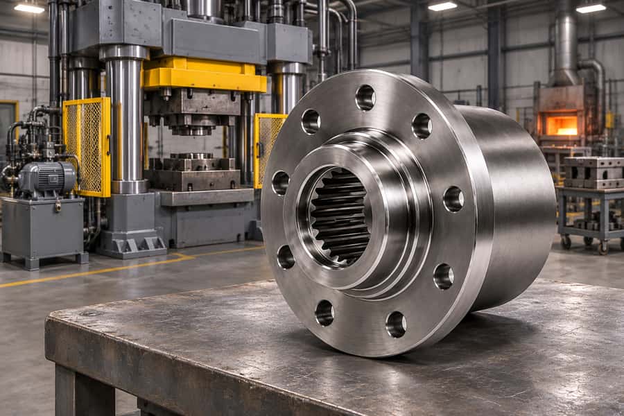
Closed die forging uses hammers or mechanical, screw, and hydraulic presses to shape heated billets inside matched dies. Cutting, heating, transfer, trimming, and inspection equipment support production.
Machine choice depends on forming energy, available force during the stroke, die geometry, material behavior, and output requirements. Thermal processing and cutting stations handle the remaining specified operations.
Four Machine Families Used to Shape Die Forgings
Closed die forging machines apply compressive loads that force metal into shaped die cavities. Hammers and presses differ in how they deliver energy, force, and deformation.
The four primary equipment categories are forging hammers, mechanical presses, screw presses, and hydraulic presses. Each offers different advantages for forming complex industrial components.
Forging Hammers
Forging hammers use impact energy to deform heated metal between shaped dies. The workpiece may receive several blows before reaching the required geometry.
Gravity drop hammers obtain energy from a falling ram. Powered hammers additionally use mechanical, pneumatic, or hydraulic systems to accelerate the ram.
Their main characteristics include:
- Impact Forming: Delivers deformation through high-energy blows.
- Flexible Forming Sequence: Allows successive blows to distribute material through die impressions.
- Process Adjustment: Operators or automated controls can manage blow sequences according to equipment configuration.
- Operating Limitations: Impact generates vibration and noise, requiring suitable foundations and protective measures.
Forging hammers can accommodate varied forming sequences, but consistent die filling depends on impact energy, billet temperature, tooling, and controlled workpiece positioning.
Mechanical Forging Presses
Mechanical forging presses generally use a motor-driven flywheel and crank or eccentric mechanism to move the ram through a fixed stroke.
Unlike hammers, these presses apply deformation through mechanically constrained ram movement. Available forming force changes with the position of the ram.
Their primary characteristics include:
- Fixed Stroke: Provides repeatable ram travel during production.
- Production Efficiency: Supports consistent forming cycles in suitable high-volume operations.
- Force Characteristics: Available force depends on crank position and machine design.
- Operating Limitations: Fixed stroke geometry and available energy restrict certain forming operations.
Mechanical presses are often considered for repetitive component production where die design, forming load, and stroke requirements are well established.
Screw Forging Presses
Screw forging presses use a rotating screw to move the ram. Mechanical or electric drive arrangements provide energy for the forming stroke.
These presses are generally energy-limited machines. The available energy must be sufficient to complete the intended deformation without exceeding equipment limits.
Important characteristics include:
- Energy Control: Forming energy can be adjusted within equipment capabilities.
- Stroke Flexibility: Operation is not governed by the same fixed crank motion used in conventional mechanical presses.
- Forming Applications: Suitable for various impression-die forging operations.
- Operating Limitations: Energy delivery, machine construction, and cycle requirements constrain production.
Selecting a screw press requires evaluating available forming energy, expected deformation, die closure requirements, and the number of necessary strokes.
Hydraulic Forging Presses
Hydraulic forging presses use pressurized hydraulic fluid and cylinders to produce controlled ram movement and compressive force.
Their force-control characteristics make them suitable for operations requiring adjustable ram movement, controlled deformation, or substantial forming loads.
Key characteristics include:
- Force Control: Hydraulic systems regulate applied force within machine capacity.
- Adjustable Movement: Ram speed and travel can be controlled according to the equipment configuration.
- Controlled Deformation: Supports forming sequences requiring deliberate compression.
- Operating Limitations: Cycle speed, hydraulic system performance, and workpiece cooling may affect productivity.
Hydraulic presses can deliver high forming forces, but their suitability depends on machine dimensions, available stroke, deformation requirements, and production speed.
Comparison of Closed Die Forging Machines
The following table summarizes the principal differences between the four equipment categories.
| Equipment | Operating Principle | Main Advantage | Key Limitation |
| Forging Hammer | Delivers impact energy through repeated blows | Flexible impact-forming sequences | Vibration, noise, and impact control |
| Mechanical Press | Uses crank-driven ram movement | Repeatable cycles and efficient production | Fixed stroke and position-dependent force |
| Screw Press | Converts rotational energy into ram movement | Adjustable energy delivery | Available forming energy |
| Hydraulic Press | Uses hydraulic pressure to generate force | Controlled force and ram movement | Cycle speed and hydraulic system limits |
No machine type is universally superior. Equipment selection must account for material flow, component geometry, deformation requirements, and expected production quantity.
How Are Forging Machine Capacity and Performance Evaluated?
A machine’s rated capacity cannot independently establish whether it can manufacture a particular forging. Engineers must compare equipment characteristics with the complete forming operation.
Forming Energy vs. Forging Force
Forming force describes the instantaneous compressive load applied to a workpiece. Forming energy represents the work available or delivered during deformation.
Energy-limited machines, including forging hammers and screw presses, must provide sufficient energy for the intended deformation while remaining within their operating limits.
Mechanical presses follow a constrained ram trajectory, with allowable force varying through the stroke. Their available energy must also satisfy the forming operation.
Hydraulic presses are primarily force-limited, although their forming performance also depends on hydraulic power, ram speed, travel, and system characteristics.
These distinctions matter because a forging operation requires sufficient loading throughout the actual deformation sequence, not merely a high maximum force.
Why Nominal Press Tonnage Is Not Enough
Nominal press tonnage indicates a rated force capacity under defined conditions. It does not specify the full force-versus-stroke characteristics or available forming energy.
Several additional parameters determine equipment suitability:
- Available Energy: Must support the deformation required during the forming operation.
- Force Distribution: Available force may change significantly with ram position.
- Stroke Length: Must accommodate billet height, tooling, and required deformation.
- Machine Stiffness: Influences elastic deflection and die alignment under load.
- Working Space: Die dimensions and equipment clearances must accommodate tooling.
- Load Distribution: Eccentric loading must remain within machine and tooling limits.
For mechanical presses, rated force is commonly associated with a specified position near the bottom of the stroke. It should not be assumed available everywhere.
Factors Affecting Equipment Selection
Component geometry influences how metal flows through die impressions. Complex shapes may require preforming operations before the final impression can be filled.
Material chemistry, forging temperature, and deformation rate also influence forming resistance. A machine suitable for one material and geometry may not suit another.
Engineers should assess the complete forming sequence, including expected load, forming energy, tooling arrangement, and production rate, before approving equipment selection.
What Equipment Is Used for Billet Preparation and Heating?
Before forging begins, raw material must be prepared into billets and brought to the required forming temperature when using a hot-forging process.
Billet Cutting Equipment
Billet cutting equipment divides bar stock or other suitable starting material into pieces of controlled dimensions and mass.
Common equipment includes:
- Band Saws: Cut billets from bar stock with controlled cutting dimensions.
- Circular Saws: Provide repeatable cuts for suitable material sections and production requirements.
- Billet Shears: Separate suitable stock through shearing, subject to material and equipment limitations.
Accurate billet preparation helps control material volume inside the dies. Excessive or insufficient billet mass can cause flash variation or incomplete filling.
Material identification and traceability should also be maintained during cutting and preparation to prevent mixing different material specifications.
Forging Heating Equipment
Hot closed die forging requires heating billets to a material-appropriate forming temperature. Heating method selection depends on stock dimensions, material properties, and production requirements.
Two common heating approaches are:
- Forging Furnaces: Fuel-fired or electric furnaces heat billets through controlled thermal exposure.
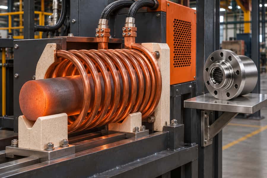
- Induction Heating Systems: Electromagnetic induction generates heat within electrically conductive workpieces using appropriately designed coils and controls.
Furnaces can accommodate different loading arrangements, while induction systems may offer efficient heating for repetitive operations involving suitable billet geometries.
Temperature uniformity is critical. Excessive heating can cause oxidation or microstructural damage, while insufficient heating can increase forming resistance and tooling loads.
The acceptable temperature range must be established for the specified alloy rather than applying one heating schedule to every material.
Billet Handling and Transfer Equipment
Heated billets must be transferred from heating equipment to the forging machine while maintaining suitable temperature and orientation.
Handling arrangements may include forging tongs, mechanical manipulators, conveyors, transfer arms, or automated feeding systems.
Equipment selection should consider:
- Transfer Time: Limits unnecessary temperature loss before forging.
- Billet Positioning: Supports proper placement inside the die impression.
- Handling Capacity: Matches billet dimensions and mass.
- Operator Protection: Reduces exposure to hot surfaces and moving equipment.
Poor transfer coordination can produce inconsistent starting temperatures, creating differences in forming loads and die filling between successive workpieces.
What Dies and Supporting Tooling Are Used?
Forging dies determine the intended component geometry, while supporting tooling maintains alignment, controls material flow, and assists with part removal.
Impression Dies and Preforming Dies
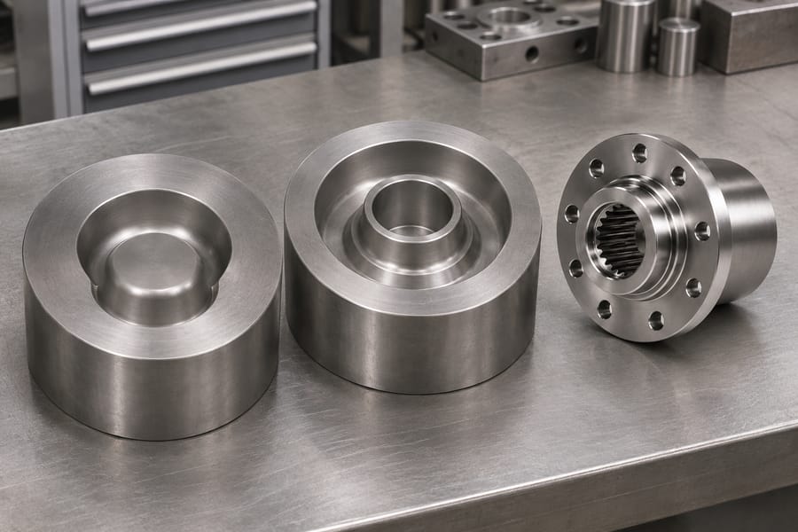
Closed die forging commonly uses upper and lower dies containing impressions that shape the workpiece during deformation.
Depending on component complexity, the tooling sequence may include:
- Preforming Dies: Redistribute material before detailed shaping.
- Blocker Dies: Produce an intermediate shape approaching the final forging geometry.
- Finishing Dies: Establish the specified forged profile and surface features.
- Flash Features: Control excess material flow in conventional flash-forming operations.
Not every forging requires separate preforming and blocker stages. Simple components may use fewer impressions, while complex shapes can require additional operations.
Die design must also account for material flow, draft, fillets, parting-line location, and allowances for subsequent machining.
Die Mounting and Alignment Equipment
Die holders, mounting components, and guiding arrangements secure tooling and help maintain alignment during forging.
Improper mounting or excessive movement can contribute to uneven loading, dimensional variation, and premature tooling damage.
Some operations use ejector mechanisms or dedicated removal devices to separate the forged component from the die after forming.
The mounting arrangement must be compatible with machine dimensions, allowable loading, and the selected tooling design.
Die Lubrication and Temperature Control Systems
Die lubrication equipment applies suitable lubricants or release agents to reduce friction and assist component removal where required.
Application systems may include manual spraying, controlled dispensing, or automated lubrication arrangements.
Die temperature management is also important because repeated contact with heated metal produces cyclic heating and cooling.
Lubrication, cooling, and die material selection influence metal flow, surface condition, thermal fatigue, and tooling service life.
Equipment That Takes the Forging Through Finishing
Forging produces the basic component geometry, but additional processing may be necessary to obtain the specified properties, surface condition, and finished dimensions.
Flash Trimming Equipment
Conventional impression-die forging often produces flash where excess metal escapes between die surfaces. Trimming equipment removes this material after forming.
A trimming press typically works with dedicated trimming dies that separate flash from the forged component.
Trimming may occur while the workpiece remains hot or after cooling, depending on the material, geometry, and manufacturing sequence.
Flashless forging does not require the same flash-removal operation, although other finishing steps may still be necessary.
Heat Treatment Equipment
Heat treatment equipment modifies microstructure and material properties according to the specified alloy and required final condition.
Equipment may include controlled furnaces, quenching systems, cooling equipment, and temperature-monitoring instruments.
Common treatments include:
- Normalizing: Used for appropriate steel grades to develop specified microstructural conditions.
- Annealing: Applied where softening, microstructural modification, or other material-specific objectives are required.
- Quenching and Tempering: Used for suitable hardenable steels to obtain specified mechanical properties.
- Solution Treatment: Applied to appropriate alloys for microstructural and corrosion-performance requirements.
- Precipitation Aging: Develops specified properties in suitable precipitation-hardening alloys.
Heat-treatment practices cannot be transferred indiscriminately between materials. Alloy chemistry, section thickness, heating uniformity, and cooling rate affect achievable properties.
Austenitic and duplex stainless steels do not quench-harden in the manner of conventional carbon steels. Suitable treatments must preserve their required microstructures and corrosion performance.
Precipitation-hardening stainless steels use controlled aging to develop properties, sometimes following solution treatment or other specification-defined conditioning.
Engineers must distinguish properties measured in the as-forged condition from those required after final heat treatment. Forging alone does not establish every finished mechanical property.
Surface Cleaning Equipment
Forged components may contain oxide scale, residual lubricants, and surface contamination that must be removed before inspection or further processing.
Common cleaning equipment includes:
- Shot Blasting Machines: Remove scale and prepare suitable metal surfaces.
- Descaling Equipment: Removes oxide through mechanical or other specified methods.
- Cleaning Systems: Remove residual processing materials before subsequent operations.
Cleaning requirements depend on surface condition, material compatibility, inspection methods, and the intended next manufacturing operation.
Machining and Straightening Equipment
Closed die forging produces a near-net shape, but precision features frequently require machining after forging and heat treatment.
Common equipment includes CNC lathes for cylindrical surfaces, milling machines for profiles, drilling machines for holes, and grinders for specified finishes.
Straightening equipment may also be needed when distortion affects component geometry and an approved correction process is available.
Machining allowances should be established from the forging design and finished drawing. They must account for process variation and required material removal.
What Inspection and Testing Equipment Is Used?
Inspection equipment verifies whether forged components meet defined dimensional, material, and quality requirements. The applicable tests depend on the drawing and purchase specification.
Dimensional Inspection Equipment
Dimensional inspection confirms that components remain within the agreed requirements before or after machining.
Typical equipment includes:
- Calipers and Micrometers: Measure accessible linear and cylindrical dimensions.
- Dedicated Gauges: Check specified features efficiently during repetitive production.
- Coordinate Measuring Machines: Evaluate suitable complex geometry and feature relationships.
- Profile Measuring Equipment: Checks selected contours and geometric characteristics.
Inspection planning should distinguish as-forged dimensions from final machined dimensions because the acceptance requirements may differ between manufacturing stages.
Mechanical and Material Testing Equipment
Mechanical testing assesses specified material properties rather than relying solely on the appearance or geometry of a forging.
The inspection plan may call for indentation measurements, a tensile loading test, or a notched impact test, each using equipment suited to the specified procedure.
Chemical analysis equipment can verify material composition, while material identification and traceability systems link inspection results to production records.
Test specimens, sampling locations, and final heat-treatment condition must be defined appropriately, particularly when section size affects the resulting properties.
Nondestructive Testing Equipment
Nondestructive testing can identify relevant discontinuities without cutting apart the inspected production component.
| Inspection Method | Main Application | Important Limitation |
| Ultrasonic Testing | Detecting and assessing applicable internal discontinuities | Geometry, microstructure, and accessibility affect examination |
| Magnetic Particle Testing | Surface and near-surface discontinuities in ferromagnetic materials | Not suitable for nonferromagnetic materials |
| Liquid Penetrant Testing | Surface-breaking discontinuities | Cannot reveal fully enclosed internal defects |
| Visual Inspection | Visible surface conditions and workmanship | Cannot reliably identify hidden discontinuities |
Inspection method selection must reflect material properties, component geometry, surface preparation, required coverage, and specified acceptance criteria.
A clean surface and an appropriate examination procedure are essential. Different methods are complementary rather than universally interchangeable.
How Should Industrial Buyers Evaluate Closed Die Forging Equipment?
Industrial buyers do not necessarily need to select an individual forging machine. They must verify that the proposed manufacturing route can meet component requirements.
Match Equipment Capabilities to Component Design
Forged shafts, flanges, couplings, gear blanks, and connecting rods impose different demands on material flow, die arrangement, and forming equipment.
Before evaluating a supplier, engineers should prepare:
- Component Drawings: Include critical features, dimensions, and machining requirements.
- Material Specifications: Define the required material and final delivery condition.
- Production Quantities: Identify expected batch size and recurring demand.
- Functional Requirements: Specify relevant mechanical properties and service conditions.
- Inspection Requirements: Establish necessary testing, documentation, and acceptance criteria.
These details allow the manufacturer to assess machine capacity, forming stages, tooling requirements, and subsequent processing needs.
Consider the Complete Manufacturing Process
The forming machine represents only one part of the total manufacturing route. Cutting, heating, transfer, trimming, heat treatment, and machining also influence production feasibility.
Buyers should examine whether the proposed process supports consistent material flow, appropriate temperature management, dimensional control, and the specified final material condition.
The following questions help identify practical manufacturing risks:
- Tooling Strategy: Does the component require preforming, blocker, or multiple finishing impressions?
- Material Utilization: How much stock is required for flash, allowances, and process-related losses?
- Heat Treatment: Which final properties must be verified after thermal processing?
- Machining Scope: Which features remain as-forged, and which require precision machining?
- Process Coordination: Are secondary operations included in the proposed manufacturing scope?
Production volume also affects tooling decisions. Complex tooling may be justified by repeat orders but can impose substantial initial preparation requirements.
Confirm Manufacturing Capabilities with the Supplier
Equipment capability should be verified against actual component requirements, not inferred from broad descriptions of available forging services.
Buyers can ask the supplier to identify the proposed forging method, machine capacity characteristics, tooling sequence, and required secondary operations.
Inspection responsibilities should be confirmed before ordering, including dimensional verification, mechanical testing, nondestructive examination, and any required material or processing records.
Where operations are performed externally, clarify responsibility for process coordination, acceptance, traceability, and delivery of compliant components.
For custom closed die forging projects, Boberry Machining can be consulted about shafts, flanges, couplings, gear blanks, connecting rods, and other industrial components.
The purchasing decision should ultimately depend on a documented manufacturing route, confirmed equipment suitability, defined final-part requirements, and agreement on inspection and delivery responsibilities.