
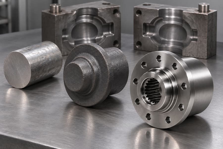
In closed die forging, shaped tooling redistributes a measured billet into the planned component profile. The manufacturing process typically involves billet preparation, heating, preforming, final forging, flash trimming, and finishing operations.
Buyers must also plan the cooling, thermal processing, material removal, and acceptance checks. These operations influence material properties, dimensional accuracy, production efficiency, and finished-part quality.
Overview of the Closed Die Forging Process
Closed die forging uses shaped die cavities to control metal deformation under compressive loading. The material flows into the cavity geometry, creating a component with defined external features.
Unlike open die forging, where material can spread more freely between relatively simple dies, closed die forging restricts deformation through its cavity design. This supports repeatable production of complex shapes.
However, a forged component does not necessarily leave the forming operation ready for installation. Flash removal, heat treatment, machining, and inspection may be necessary before acceptance.
Main Manufacturing Stages
The following table summarizes the typical manufacturing sequence and the quality considerations associated with each stage.
| Process Stage | Main Operation | Quality Checkpoint |
| Billet Preparation | Select and cut raw material | Composition, dimensions, surface condition |
| Heating | Heat billets for deformation | Temperature uniformity |
| Die Preparation | Prepare shaped forging dies | Alignment, cavity condition |
| Preforming | Redistribute billet material | Material distribution |
| Final Forging | Form the required geometry | Die filling, visible defects |
| Flash Trimming | Remove excess material | Edge condition, residual flash |
| Cooling and Heat Treatment | Control cooling and modify properties | Microstructure, mechanical properties |
| Surface Cleaning | Remove scale and contamination | Surface condition |
| Machining | Produce specified dimensions | Geometry, surface finish |
| Final Inspection | Verify product requirements | Dimensions, material properties, documentation |
Not every component requires every operation. The selected manufacturing route depends on the material, part geometry, order quantity, and applicable engineering specifications.
For example, a forged gear blank may require substantial machining to produce its teeth, while another component may retain more of its original forged surfaces.
Step 1 – Material Selection and Billet Preparation
Selecting the Forging Material
Material selection begins with the engineering drawing and the component’s intended operating conditions. Strength, toughness, corrosion resistance, temperature exposure, and wear requirements can influence the specified alloy.
Carbon steels, alloy steels, and suitable stainless steels may be considered for closed die forging. However, individual grades have different hot-working characteristics and heat-treatment requirements.
The material specification should identify the required grade and any applicable chemical composition limits. Where necessary, purchasing documents should also define traceability and testing expectations.
Engineers must consider section thickness alongside alloy chemistry. Two components made from the same nominal grade may develop different properties after heat treatment because their cooling rates differ.
Cutting and Preparing the Billet
Once the material is selected, raw stock is cut into billets sized for the intended forging geometry.
Billet volume must account for the finished component, machining allowances, flash formation where applicable, and other expected processing losses.
An undersized billet may prevent complete cavity filling. Excessive billet volume can increase flash, forming loads, die stresses, and material waste.
Before heating, operators may check several billet characteristics:
- Dimensions: Confirm the cut length and cross-sectional size.
- Weight: Verify the planned material volume.
- Surface condition: Identify cracks, seams, or other visible irregularities.
- Material identification: Maintain traceability where required.
- Cut quality: Check for excessive burrs or irregular end surfaces.
Proper billet preparation reduces avoidable variation before the material enters the forging process.
Step 2 – Billet Heating and Die Preparation
Heating the Billet
Most conventional hot closed die forging operations begin by heating billets to a temperature range suitable for plastic deformation.
Heating reduces resistance to deformation, allowing the material to flow into shaped cavities without requiring the same loads associated with colder forming conditions.
The appropriate temperature window depends on the material specification. Applying a heating schedule developed for one alloy to another can cause processing difficulties.
Temperature distribution also matters. An unevenly heated billet may deform inconsistently, increasing the risk of incomplete filling, unfavorable flow patterns, or localized defects.
Prolonged exposure to elevated temperatures can promote oxidation, surface scaling, or undesirable microstructural changes. Heating time therefore requires control as well as temperature.
Billets also lose heat during transfer from the heating station to the forging dies. Transfer time and handling arrangements must be considered when establishing the forming sequence.
Preparing and Checking the Forging Dies
The forging dies contain shaped cavities corresponding to the intended component geometry, with allowances for deformation behavior, shrinkage, and subsequent processing.
Several die design features influence manufacturing performance:
- Parting line: Defines where the die halves meet and influences flash formation.
- Draft angles: Help release the forged component from the cavity.
- Fillet radii: Support material flow around corners and transitions.
- Flash lands and gutters: Control excess metal flow in flash-type forging.
- Cavity dimensions: Account for the intended forged geometry and processing allowances.
Before production, die surfaces, alignment, lubrication arrangements, and operating conditions require appropriate checks.
New components may also require die trials and dimensional evaluation. These activities help identify filling problems or geometry adjustments before repeat production begins.
Step 3 – Preforming and Final Forging
Preforming the Heated Billet
Complex closed die forgings may undergo preliminary shaping before entering the final forging cavity.
Preforming redistributes material toward regions that require greater volume, such as enlarged ends, flanges, bosses, or substantial cross-sectional transitions.
Depending on component design, this stage may involve preliminary deformation or blocker cavities that produce an intermediate shape.
A properly designed preform can improve cavity filling and reduce excessive material movement during final forging.
However, additional forming stages increase tooling requirements and handling operations. Engineers must balance improved material distribution against production complexity.
Final Forging in Shaped Die Cavities
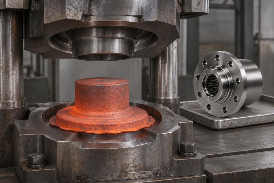
During final forging, compressive loading forces the heated material to conform to the finishing die cavities.
As deformation continues, material flows into geometric features until the required cavity shape is sufficiently filled under the established process conditions.
In conventional flash-type closed die forging, excess material escapes through a narrow opening near the parting line, producing flash around the component.
The flash region creates resistance to outward metal flow, helping promote cavity filling. Its geometry must be designed alongside the component cavity.
Flashless closed die forging uses a different approach. Material volume and cavity conditions must be controlled closely because the process does not rely on conventional flash escape.
Neither method automatically suits every component. Geometry, material behavior, production quantity, and process-control requirements influence the selection.
The deformation sequence also affects grain flow and internal structure. However, favorable grain orientation cannot be assumed solely because a component was forged.
Actual properties depend on alloy chemistry, deformation history, section geometry, cooling conditions, and any subsequent heat treatment.
Common Forging Defects and Process Controls
Closed die forging can produce defects when material flow, heating, billet preparation, or die conditions are unsuitable.
Common concerns include:
- Underfilling: Metal fails to occupy part of the intended die cavity.
- Laps and folds: Material surfaces overlap or fold during deformation.
- Surface cracking: Localized deformation or unsuitable forming conditions damage the material.
- Excessive flash: Unnecessary material escapes around the parting line.
- Dimensional variation: The forged geometry differs from the intended as-forged condition.
Preventive controls include appropriate billet volume, controlled temperatures, suitable preforming geometry, correct die alignment, and stable forming conditions.
Visual checks and intermediate dimensional measurements can identify problems before additional manufacturing operations increase the value of a defective component.
Step 4 – Flash Trimming and Secondary Forming
Removing Excess Flash
Flash trimming removes unwanted material around the parting line after conventional flash-type closed die forging.
The operation may be performed while the forging retains elevated temperature or after cooling, depending on material behavior and the selected production route.
Trimming tooling must separate flash without damaging the intended component geometry.
Poor trimming can leave residual flash, irregular edges, or localized damage that complicates machining and inspection.
The trimmed component should therefore be examined for edge condition and unwanted material remaining around critical features.
Additional Forming Operations
Certain forgings require secondary operations before entering the finishing stages.
Examples include:
- Piercing: Creating or opening specified internal features where appropriate.
- Sizing: Improving selected as-forged dimensions through additional controlled deformation.
- Straightening: Correcting distortion in suitable component geometries.
These operations are not universal requirements. Their necessity depends on the component drawing, achievable forged geometry, and intended downstream machining route.
For example, a shaft forging may need straightness correction, while a flange forging may require machining rather than forming to establish its final bore.
Step 5 – Cooling, Heat Treatment, and Surface Cleaning
Controlled Cooling After Forging
After forming, the component undergoes cooling according to the material and the selected manufacturing specification.
Cooling rate can influence microstructure, hardness, residual stress, and dimensional stability. Rapid or uneven cooling may create undesirable property variations or distortion.
The appropriate cooling method depends on alloy chemistry, section size, and intended mechanical properties.
For thick sections, temperature differences between the surface and interior can be substantial. These differences require consideration when planning cooling and subsequent heat treatment.
Heat Treatment for Required Properties
Heat treatment may be necessary to establish the mechanical properties specified for the finished component.
Depending on material grade and requirements, possible treatments include:
- Annealing: Used for specified softening, microstructural changes, or processing requirements.
- Normalizing: Applied to suitable steels to establish a specified microstructure and property condition.
- Quenching: Used with suitable hardenable alloys to develop the intended hardened structure.
- Tempering: Applied after hardening where required to adjust hardness, strength, and toughness.
- Solution treatment and aging: Used for particular alloy systems under grade-specific processing conditions.
These treatments cannot be applied interchangeably.
For example, suitable carbon and alloy steels may develop increased hardness through quenching followed by tempering. Austenitic and duplex stainless steels do not quench-harden through the same martensitic transformation.
Solution treatment and subsequent cooling of suitable stainless grades serve different metallurgical purposes. Precipitation-hardening stainless steels rely on specified aging treatments to develop their intended properties.
A forged component’s as-forged properties must therefore be distinguished from its final heat-treated condition.
Section thickness also matters. Cooling differences between thick and thin regions can influence hardness, microstructure, and achievable mechanical properties after treatment.
When purchasing heat-treated forgings, buyers should specify the required material condition and acceptance criteria rather than assuming all products of one nominal alloy have identical properties.
Surface Cleaning and Preparation
Forging and heat treatment can leave oxide scale, residues, or surface contamination that must be addressed before further processing.
Cleaning methods are selected according to material compatibility, surface requirements, and downstream manufacturing operations.
Proper cleaning improves visibility during surface inspection and helps prepare the component for machining or other specified finishing operations.
The sequence may vary. Some components require cleaning before heat treatment, additional cleaning afterward, or surface preparation between inspection stages.
Step 6 – Machining the Forging into a Finished Part
Determining Machining Allowances
Closed die forging produces a shape approaching the final component geometry, but many industrial parts require subsequent machining.
Machining allowances provide additional material that can be removed to establish specified dimensions, geometry, and surface conditions.
For example, a forged shaft may retain additional material around bearing seats, while a flange may require machining on its sealing face and bolt-hole features.
Allowances must accommodate forging variation, suitable workholding, datum establishment, and expected material removal.
Excessive allowances increase machining time and waste. Insufficient allowances can leave inadequate material to produce the required finished surfaces.
Common Machining Operations
Several machining methods may be used according to component geometry and drawing requirements.
- Turning: Produces cylindrical diameters, shoulders, and rotational surfaces.
- Milling: Creates flats, slots, pockets, and selected mounting features.
- Drilling: Produces specified holes and prepares features for subsequent operations.
- Boring: Finishes internal diameters and improves selected bore geometry.
- Grinding: Supports specified dimensional accuracy or surface finish where required.
The selected combination depends on the component rather than a universal sequence.
A forged coupling may require turning and boring, while a connecting rod can involve multiple machining setups to establish its functional interfaces.
Balancing Near-Net-Shape Forging and Machining
A closer as-forged shape can reduce the amount of stock removed during machining. However, achieving that shape may require more complex tooling.
Engineers should evaluate the total manufacturing route instead of focusing exclusively on forging dimensions.
| Evaluation Item | As-Forged Component | Finished Machined Component |
| Geometry | Defined by die cavities and forming conditions | Defined by specified machining operations |
| Dimensional Requirements | Subject to agreed forging requirements | Subject to final drawing requirements |
| Surface Condition | May contain scale or forging-related marks | Machined surfaces meet specified finish requirements |
| Critical Holes and Bores | May be partially formed or left solid | Produced or finished to required dimensions |
| Inspection | Focuses on forging condition and applicable features | Verifies finished dimensions and functional features |
| Material Removal | Limited or absent after forging | Depends on machining allowances |
For repeat-production orders, the balance between tooling complexity and machining effort can materially influence manufacturing efficiency.
For smaller quantities, simplifying the forging geometry may be more practical when the resulting machining work remains manageable.
Step 7 – Quality Inspection and Finished-Part Verification
In-Process Inspection
Quality inspection should not be postponed entirely until the component reaches its final condition.
Checks during billet preparation, heating, forging, trimming, and finishing can identify problems before they affect later operations.
For example, incomplete die filling may be visible after forging. Detecting the issue before heat treatment and machining avoids unnecessary processing.
Checks can be assigned to these production stages:
- Billet checks: Confirm the stock identity, cut size, and visible condition before heating.
- Heating checks: Appropriate temperature and process conditions.
- Forging checks: Cavity filling, shape, and visible surface defects.
- Trimming checks: Edge quality and residual flash.
- Heat-treatment checks: Recorded processing conditions and specified property verification.
The inspection frequency and documentation requirements should reflect the component’s manufacturing plan and agreed acceptance criteria.
Dimensional and Surface Inspection
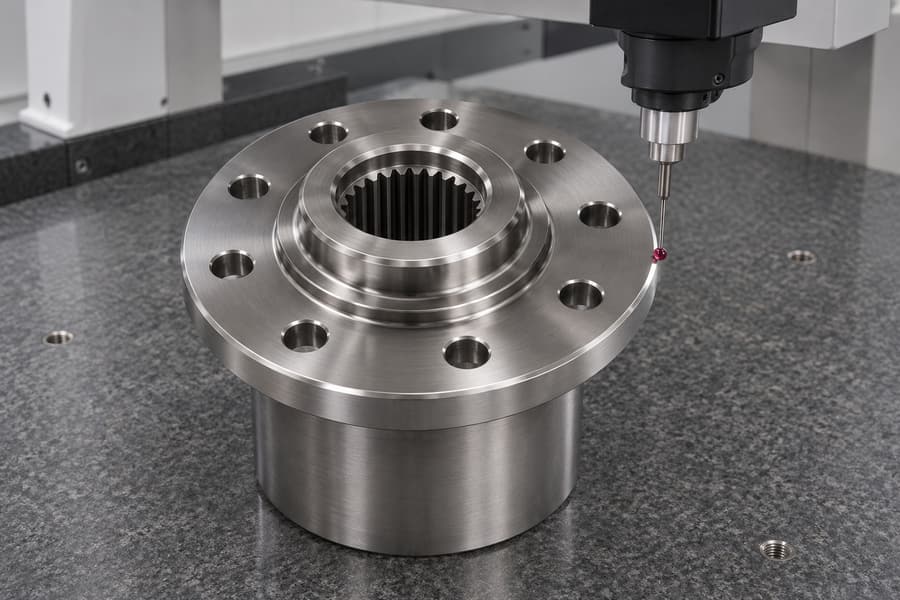
Dimensional inspection establishes whether the component satisfies its applicable drawing requirements.
As-forged measurements may focus on overall geometry, stock allowance, and features needed for subsequent processing.
Finished-part inspection focuses on specified dimensions, geometric relationships, and critical functional interfaces.
Surface examination should also consider cracks, laps, folds, trimming damage, and other relevant discontinuities.
Inspection methods must suit the surface condition and applicable acceptance standard. Rough forged surfaces may require preparation before certain examinations can be performed reliably.
Material Testing and Nondestructive Examination
Material verification can include chemical analysis, hardness measurement, and mechanical testing when required by the specification.
Mechanical testing requirements may involve tensile or impact properties, with test-piece locations and orientations established by the applicable requirements.
Nondestructive examination may also be appropriate for selected components.
Common methods include:
- Ultrasonic testing: Evaluates suitable internal regions for relevant discontinuities, subject to material, geometry, and testability.
- Magnetic particle testing: Reveals relevant indications at or just below the surface when the material can be magnetized.
- Penetrant testing: Identifies surface-breaking discontinuities on appropriately prepared surfaces.
The inspection plan needs complementary methods because each examination leaves some defect types outside its scope.
The examination procedure, coverage, sensitivity, and acceptance criteria must be established for the specified component rather than assumed from the manufacturing process.
Final Documentation and Delivery Preparation
After completing the required operations, inspection results should be reviewed against the approved drawing and purchase requirements.
Documentation may include material identification, chemical analysis, heat-treatment records, dimensional inspection results, and specified mechanical or nondestructive testing reports.
The required document package should be established during purchasing rather than negotiated only after manufacturing.
Depending on the application, components may also require identification markings, corrosion protection, protective packaging, or specific handling arrangements.
These requirements help preserve the accepted product condition during storage and transportation.
Engineering and Purchasing Considerations for Closed Die Forgings
Component Geometry and Production Quantity
Closed die forging is particularly useful when a component’s geometry and production requirements justify shaped tooling.
However, intricate features, abrupt section changes, deep cavities, and difficult parting-line arrangements can increase forming complexity.
Engineering review should consider whether small design adjustments could improve material flow or simplify subsequent machining without compromising functionality.
Production quantity also affects manufacturing decisions because tooling expenditure is distributed across the expected number of acceptable parts.
A repeat-production component may justify more elaborate tooling to reduce machining work. A smaller order may benefit from simpler forged geometry and additional machining.
Material utilization is another consideration. Billet size, flash losses, rejected parts, and machining allowances influence the amount of material required per accepted component.
Buyers should evaluate these factors together rather than choosing a forging route based on nominal material weight alone.
Requirements for Custom Closed Die Forging Orders
A complete technical inquiry allows the manufacturing route to be evaluated against the finished component’s actual requirements.
For custom shafts, flanges, couplings, gear blanks, connecting rods, and industrial components, buyers should prepare the following information:
- Engineering drawings: Include dimensions, critical features, geometric requirements, and applicable revisions.
- Material specifications: Identify the required grade, chemical composition requirements, and material condition.
- Order quantities: Specify the initial quantity and expected repeat-production demand where known.
- Heat-treatment requirements: Define the required final properties or specified material condition.
- Machining scope: Clarify which surfaces must be finished and which may remain as-forged.
- Inspection requirements: State applicable test methods, examination coverage, and acceptance criteria.
- Documentation: Identify required material records, inspection reports, and traceability information.
- Delivery requirements: Specify identification, preservation, packaging, and expected delivery arrangements.
These details also establish whether the purchase covers an as-forged blank, a heat-treated forging, or a fully machined component.
When reviewing a proposal from Boberry Machining, buyers should confirm the proposed manufacturing scope, including which operations and inspections are included.
A drawing with clearly identified functional surfaces is particularly valuable. It allows machining allowances and inspection requirements to be matched to the features that matter.
For components with substantial section changes, buyers should also discuss heat-treatment feasibility and where specified mechanical properties must be demonstrated.
Before releasing an order, confirm the approved drawing revision, final material condition, machining responsibilities, inspection plan, documentation package, and acceptance requirements.