
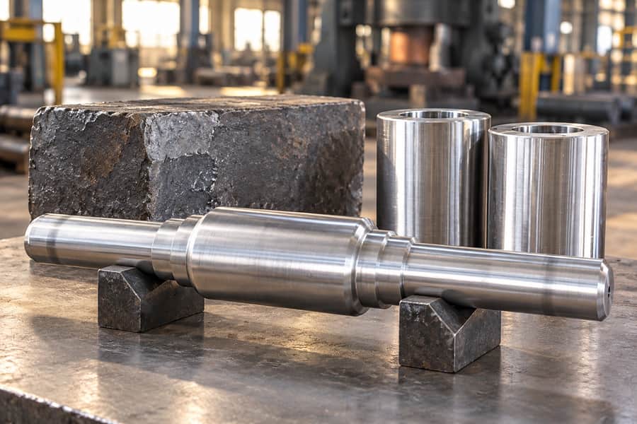
Radial forging and conventional open die forging produce industrial preforms through repeated compression, but their equipment and deformation sequences differ. Selection depends on geometry, material, starting stock, and finishing requirements.
This comparison concerns dedicated multi-hammer radial forging and traditional two-die cogging. Neither method automatically provides superior internal quality, tighter tolerances, or lower production cost.
Radial Forging vs Open Die Forging: What Is the Difference?
How Dedicated Radial Forging Works
Dedicated radial forging equipment uses several dies arranged around a workpiece. Their coordinated strokes reduce its cross-section while the stock advances axially, often with controlled rotation.
The arrangement is especially relevant to long, predominantly axisymmetric stock. Solid bars and tubular preforms can be candidates, although the achievable profile depends on machine configuration and tooling.
For hollow sections, a mandrel may support or help shape the bore. Its use, accessibility, and effect on wall thickness require a separate process assessment.
The stock must also remain accessible throughout feeding and tool engagement. End effects and profile transitions can limit how much of its length is forged.
How Conventional Open Die Forging Works
Conventional open die forging commonly compresses stock between two opposing flat or shaped dies. Between successive die compressions, the workpiece is turned or shifted to expose another section for deformation.
Cogging draws material into longer sections through overlapping compressions. Upsetting increases cross-section locally or overall, while other die arrangements can establish steps and rough profiles.
Hydraulic presses deliver controlled force through a stroke; forging hammers deliver impact energy. Both can deform substantial sections when material temperature, reduction, and die contact are appropriate.
Why the Terminology Matters
Radial forging may itself fall within the broad open-die family because the tooling does not fully enclose the material. The comparison here is equipment-specific, not a universal classification.
Rotary swaging, orbital forging, and ring rolling use different tooling arrangements or deformation sequences. Their capabilities should not be transferred automatically to dedicated multi-hammer radial forging.
Key Manufacturing Differences Between Radial Forging and Open Die Forging
| Comparison Factor | Dedicated Radial Forging | Conventional Two-Die Forging | Engineering Implication |
| Die action | Coordinated compression from several radial directions | Successive reductions between opposing dies | Contact and deformation histories differ |
| Stock movement | Axial feed, often with rotation | Repositioning, rotation, drawing, or upsetting | Handling affects profile and uniformity |
| Typical geometry | Long, mainly axisymmetric sections | Shafts, blocks, disks, and varied preforms | Shape is an early screening criterion |
| Hollow sections | Mandrel or other arrangements may be feasible | Hollow and mandrel-forging sequences may be feasible | Bore strategy needs separate review |
| Size limits | Machine opening, feed, working range, and handling | Die opening, stroke, load or energy, and handling | Check the actual equipment, not labels |
| Setup | Specialized dies and production settings | Die selection and forging sequence planning | Quantity and geometry influence economics |
Deformation Method and Material Flow
Radial dies apply repeated compression around the outside, coupled with stock feed. Conventional cogging applies successive bites whose orientation changes as the workpiece is rotated or repositioned.
Neither description establishes how uniformly the center deforms. Starting section, reduction schedule, friction, temperature, and die contact influence strain distribution and resulting internal structure.
Where internal performance is critical, request a process rationale tied to section geometry and inspection requirements rather than relying on general statements about compressive working.
An elongated shaft also may need local steps or shoulders. Their feasibility depends on die form and planned material displacement, not simply whether the machine can reduce diameter.
Shape Flexibility and Equipment Limitations
A radial machine may efficiently develop suitable external profiles along long stock. However, bulky flanges, irregular blocks, or abrupt changes in section may demand another forming sequence.
Two-die operations offer flexibility through drawing, upsetting, and repositioning, but maximum stock mass and dimensions remain constrained by press or hammer capacity and manipulation equipment.
Check starting diameter, length, cross-section, weight, and access for tooling before comparing routes. An apparently compatible finished drawing may still require impractical starting stock or handling.
The planned preform may include temporary gripping or handling stock. Removing these features changes the material yield calculation and sometimes the machining sequence.
Production Efficiency and Manufacturing Costs
Forging cost includes starting material, preparation, heating, passes, handling, tooling, and rejects or rework. Later heat treatment, machining, and inspection may be equally important.
A suitable radial process might reduce external stock removal, particularly on repeated axisymmetric components. That benefit can disappear if setup, bore machining, or special tooling dominates.
Conversely, conventional forging may accommodate varied preforms without a dedicated radial setup. It is not automatically cheaper; yield, complexity, quantity, and finishing scope must be compared.
Which Forging Process Fits Different Industrial Components?
| Component | Radial Forging Consideration | Conventional Forging Consideration | Main Decision Point |
| Forged shafts | Candidate for long axisymmetric profiles | Suitable for drawn and stepped shaft blanks | Length, shoulders, reduction, stock |
| Thick-wall hollow sleeves | Possible with suitable stock and bore strategy | Hollow or mandrel routes may be possible | Bore access, wall thickness, allowance |
| Rotors | Candidate for shaft-like preforms | Useful for bulky or stepped rotor blanks | Mass distribution and section changes |
| Flanges | Limited to compatible profiles or preforms | Upsetting may form substantial flange sections | Flange proportions and stock |
| Rings | Not interchangeable with ring rolling | Mandrel forging may suit some ring preforms | Diameter, section, downstream route |
| Gear blanks | Possible for cylindrical preforms | Often appropriate for disks and stepped blanks | Blank shape and machining |
| Heavy blocks | Usually less appropriate | Common candidate where capacity permits | Section size, mass, reduction schedule |
Forged Shafts and Shaft-Type Rotors
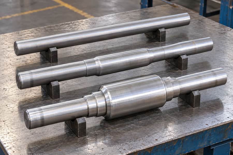
Long forged shafts are logical candidates for radial-process evaluation when their profiles remain largely axisymmetric. Diameter transitions, local shoulders, and end geometry still need individual assessment.
Conventional cogging can produce substantial shaft blanks through repeated drawing and rotation. Where an end flange or large journal is required, upsetting and additional shaping may be involved.
For either route, specify the preform rather than expecting finished bearing seats directly from forging. Straightness, cleanup stock, and heat-treatment distortion influence the subsequent machining plan.
Thick-Wall Hollow Cylinders and Sleeves
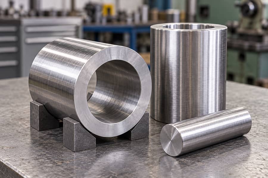
Heavy forged cylinder sleeves introduce a second geometry problem: internal as well as external dimensions. Outside diameter reduction does not, by itself, determine bore accuracy.
Radial processing may be considered for compatible tubular starting stock, with mandrel support where feasible. Conventional hollow forging may involve piercing or working an existing opening over a mandrel.
The preferred route depends on bore length, access, wall-thickness distribution, and required stock for boring. A hollow preform may still need extensive internal machining.
If a sleeve is specified by finished inside and outside diameters, the quotation must also address how eccentric as-forged stock will be located for machining.
Flanges, Rings, and Gear Blanks
Flange and disk-like blanks often involve significant material redistribution across a short axial length. Conventional upsetting and local shaping may be better matched to these proportions.
Ring preforms can be made through suitable hollow or mandrel operations. Ring rolling is a distinct process and should not be presented as another name for radial forging.
Gear blanks require appropriate stock distribution and machining allowance around their hubs and rims. Neither process ordinarily establishes the finished tooth geometry of a precision gear.
A ring-shaped forging may also be only an intermediate blank. Whether later ring rolling is appropriate requires its own equipment and section-design evaluation.
Heavy Forged Blocks and Large Rotor Preforms
Large blocks and bulky rotor preforms need sufficient equipment capacity, thermal control, and an achievable reduction plan. Their shapes generally favor flexible sequential forging over dedicated radial operations.
That preference remains conditional. A very large shaft-like rotor or an unusually shaped block can change the assessment, especially when handling and reheating become limiting factors.
How Do Forging Methods Affect Quality, Tolerances, and Machining?
Internal Quality and Mechanical Properties
Material quality begins before forging. Ingot or billet soundness, segregation, inclusions, and prior processing affect the stock available for either deformation route.
Forging may alter structure and help consolidate certain discontinuities under suitable conditions, but no named process automatically removes every inherited defect. Section size and applied strain matter.
Grain flow also follows actual deformation rather than a marketing diagram. Property requirements should identify test location, orientation, heat-treatment condition, and applicable acceptance criteria.
Forging Tolerances and Machining Allowances
As-forged tolerance describes allowable variation in the forging itself. Machining allowance is stock reserved for later removal; a finished machining tolerance applies only after machining.
A controlled radial setup may deliver consistent external profiles on suitable workpieces, but roundness, diameter variation, and straightness are not guaranteed without agreed process limits.
Traditional open die preforms likewise depend on dies, manipulation, temperature, and cooling. Neither process should be quoted against finished-machine tolerances unless the quotation explicitly includes machining.
Allowances must cover expected dimensional variation, surface cleanup, and possible centerline displacement. Insufficient stock on one side can cause a finished diameter to fail despite adequate nominal allowance.
For a shaft with critical journals, confirm how the supplier establishes the machining centerline. A nominal oversized diameter alone does not prove every journal will clean up.
Bore Accuracy in Hollow Forgings
A mandrel can influence bore formation, yet its presence does not guarantee concentricity or a uniform wall. Feed, deformation, starting eccentricity, and tooling support still matter.
Define which bore dimensions are as-forged and which are machined. Straightness, taper, wall thickness, and relationships to external datums need separate evaluation and measurement plans.
For long sleeves, the feasibility of subsequent boring may govern stock selection more strongly than an attractive as-forged outside diameter. Access and clamping are practical constraints.
Heat Treatment, Inspection, and Final Machining
Heat treatment is specified by alloy, required properties, and section size. It can also affect straightness and dimensions, so final machining may be scheduled after thermal processing.
Ultrasonic examination, appropriate surface testing, mechanical tests, and dimensional checks answer different questions. Their methods, coverage, timing, and acceptance criteria belong in the purchase specification.
Inspection access also changes after machining. Agree whether examinations occur on a rough forging, a heat-treated preform, or a finished surface before ordering.
Turning, milling, boring, and grinding may establish functional surfaces after forging. A precise final bore or bearing journal demonstrates machining capability, not necessarily tight as-forged tolerances.
How to Select the Right Forging Process for Your Project
Evaluate Geometry and Starting Stock
Begin with the finished drawing, then determine what the forging preform must contain. Identify major diameters, section transitions, bore requirements, datum relationships, and inspection-critical regions.
Compare potential starting stock with the required shape changes. A long cylindrical part favors one screening path, whereas a thick disk with a narrow hub favors another.
Material grade and section size determine workable temperature and deformation considerations. Equipment suitability must be verified before treating any process route as a procurement commitment.
Compare Finishing Scope and Total Cost
Estimate total material input, forging operations, heat treatment, machining, and inspection under the same delivery boundary. Comparing forging-only quotations with finished-part quotations obscures the decision.
Order volume matters, but so do reheat frequency, tooling preparation, difficult setup, and scrap risk. Request clarification of the starting stock, forging sequence, tooling, and production conditions used to develop each proposed manufacturing route.
The most useful comparison is between manufacturable preforms that meet the same final requirements. A superficially neater forging is not necessarily the least costly finished component.
Where quotations differ, request separate assumptions for scrap allowance, machining responsibility, and testing. Those differences can explain price variation more accurately than the selected forging label.
Three Hypothetical Project Decisions
Hypothetical project A — Long stepped shaft. A shaft has several coaxial diameters and a long central section. Radial forging merits evaluation if the transitions suit the dies and feed arrangement.
Conventional cogging remains an option when starting-stock size, shoulders, or local reductions call for a different sequence. Both routes need machining stock at journals and ends.
Hypothetical project B — Thick-wall sleeve. A hollow sleeve requires a controlled bore and adequate wall thickness after machining. Compare tubular stock, mandrel feasibility, and internal boring access.
If bore accuracy requires extensive machining, external forging precision alone may offer little benefit. The decision turns on total material, feasible reductions, and finished concentricity.
Hypothetical project C — Heavy rotor or flange blank. A bulky preform needs substantial cross-section redistribution. Conventional upsetting and cogging may offer a more practical sequence than dedicated radial tooling.
The selection still depends on material, equipment range, intended section reductions, and final machining. These examples illustrate evaluation logic, not completed customer projects or proven savings.
What Information Should Buyers Include in a Forging RFQ?
Drawings, Materials, and Component Dimensions
Provide the latest drawing revision and identify the final part versus its proposed forging envelope. Clear dimensional scope helps suppliers assess realistic manufacturing routes.
If an existing drawing shows only finished dimensions, ask for a proposed preform sketch. Review that sketch before accepting any stock or tooling assumptions.
- Geometry: Overall dimensions, critical diameters, shoulders, bore dimensions, and datum references.
- Material: Grade, specification, requested delivery condition, and service concerns.
- Quantity: Order volume, anticipated repeat orders, and delivery expectations.
- Allowances: Defined machining stock, functional surfaces, and cleanup priorities.
Manufacturing and Inspection Requirements
Specifications should separate mandatory acceptance conditions from preferred manufacturing methods. Requiring a named forging method without explaining the functional need may exclude workable alternatives.
- Supply scope: Forging only, or forging with heat treatment and machining.
- Testing: Required mechanical tests, nondestructive examination, coverage, and acceptance criteria.
- Documents: Material certificates, traceability, heat-treatment records, and inspection reports.
- Measurement: Final versus as-forged dimensions, datum strategy, and inspection stage.
Confirm the Proposed Forging Route
Before ordering, confirm starting-stock suitability, feasible reductions, machine and handling limits, and any bore-control assumptions. Ask which conditions require machining or a revised preform.
The quotation should clearly identify included operations and proposed acceptance checks. Any unresolved requirement for wall thickness, internal soundness, or finishing stock needs discussion before release.
Custom Forging Solutions from Boberry Machining
Boberry Machining supports drawing-based evaluation of custom forged shafts, thick-wall sleeves, rotors, flanges, rings, gear blanks, and heavy blocks, subject to confirmed manufacturing requirements.
Share drawings, material specifications, quantities, machining scope, and inspection requirements. Boberry Machining can review the proposed forging route and custom supply scope without presuming availability of dedicated radial equipment.
Any proposed process, subcontracted operation, or specialized equipment requirement should be confirmed against the drawing before production commitments or acceptance conditions are finalized.