
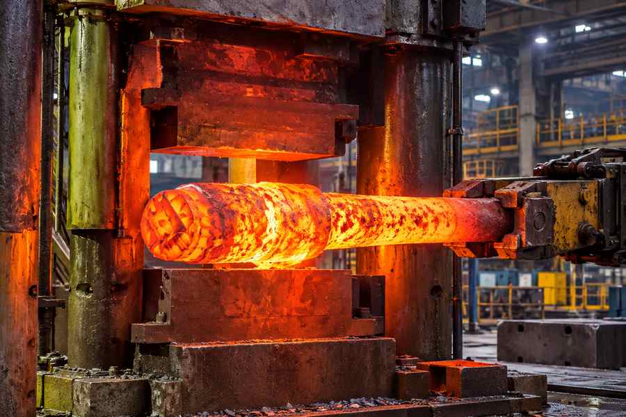
Open die forging reshapes heated metal through successive compressions between dies that do not fully surround the workpiece. Between strokes, operators rotate and advance the stock, directing metal flow into a longer, thicker, or stepped form.
The manufacturing route then combines controlled heating, repeated forming, cooling, heat treatment, machining, and inspection to produce a component meeting its specified requirements.
How Open Die Forging Works: Basic Principles and Equipment
In open die forging, flat or simply shaped dies apply compressive force to metal while leaving parts of the workpiece unconstrained. Unconstrained metal can spread beyond the die contact area.
A hydraulic press applies controlled compressive force, while a forging hammer delivers repeated impacts. Handling equipment positions, advances, and rotates the workpiece between successive forming operations.
Unlike closed die forging, the process does not depend on filling a detailed impression cavity. Instead, the required shape develops through repeated deformation and controlled movement.
This flexibility makes open die forging suitable for straight shafts, stepped shafts, blocks, discs, and other relatively simple industrial components.
However, the dies establish an approximate profile rather than finished precision surfaces. Machining subsequently produces critical diameters, bearing seats, shoulders, and other features requiring tighter dimensional control.
Open Die Forging Process: Step-by-Step Manufacturing
Step 1: Review Engineering Requirements and Prepare the Starting Material
Manufacturing begins with the component drawing, material specification, and delivery requirements. These documents determine the starting stock, deformation sequence, machining allowances, and necessary inspection operations.
Engineers examine finished dimensions, critical cross-sections, service loads, material grade, and required mechanical properties. They also identify areas requiring substantial deformation or additional machining stock.
Starting materials may include cast ingots, rolled billets, or previously worked blooms. Their dimensions, production histories, and internal conditions influence the subsequent forging plan.
Material identification and traceability are checked before cutting or heating. Chemical analysis records and available inspection information help establish whether the stock meets the specified requirements.
Cast ingots may require head and bottom discard to remove regions affected by solidification-related segregation, shrinkage, or other unacceptable conditions. Discard locations and quantities depend on ingot characteristics and applicable requirements.
Rolled billets follow different preparation practices. Cutting a billet to length does not automatically require the same head and bottom discard procedure used for cast ingots.
The prepared stock must contain sufficient material for the planned deformation, expected processing losses, and machining allowances. Insufficient starting volume can leave critical sections undersized.
Step 2: Heat the Material to the Required Forging Temperature
The prepared material enters a heating furnace, where temperature is raised according to the alloy and planned deformation operations.
Heating reduces resistance to plastic deformation, allowing compressive forces to change the workpiece geometry. Temperature uniformity is particularly important when forging large or thick sections.
The heating schedule considers material composition, starting temperature, section thickness, and furnace conditions. Suitable soaking allows the interior to approach the required working condition.
Insufficient heating can increase forming loads and cracking risk. Excessive temperature or prolonged exposure may cause undesirable grain growth, oxidation, or other metallurgical damage.
Temperature readings, heating duration, and furnace records provide evidence that the specified procedure was followed. The suitable temperature range for forging must be determined according to the specific material grade.
Step 3: Remove Surface Scale and Prepare for Deformation
High-temperature exposure produces oxide scale on many metal surfaces. Loose or heavy scale can interfere with die contact and become trapped within surface folds.
Before substantial deformation, operators remove scale using suitable mechanical or equipment-specific methods. The chosen technique depends on workpiece size, temperature, and available handling arrangements.
The exposed surface is checked for visible discontinuities that could worsen during compression. Additional descaling may be necessary after reheating or between forging passes.
Step 4: Perform Initial Upsetting or Drawing Operations
The initial forming operation establishes a workable intermediate shape. Depending on component geometry, the process may begin with upsetting, drawing out, or another suitable deformation sequence.
Upsetting compresses the workpiece along its length or height, causing material to spread laterally. It is useful when a larger cross-section is required.
For example, a shaft requiring a thickened end may undergo localized upsetting to redistribute material toward that region before subsequent shaping.
During upsetting, friction at the die interfaces restricts local movement. This can produce barreling, where the workpiece becomes wider around its middle.
Workpiece alignment, initial geometry, temperature, and compression sequence influence whether deformation remains controlled. Excessive slenderness or poor positioning may contribute to buckling or uneven material flow.
Drawing out produces the opposite overall dimensional change. Compression reduces cross-sectional area while increasing workpiece length, making it suitable for elongated components.
Some forging routes combine these operations. A section may first be upset to redistribute material, then drawn to establish the required shaft proportions.
The selected sequence must reflect the final geometry and starting stock. Applying unnecessary upsetting simply because it appears in a standard process description adds work without establishing a useful manufacturing benefit.
Step 5: Draw Out the Workpiece Using Overlapping Die Bites and Rotation
Drawing out is a central operation in manufacturing long open die forgings. The workpiece is progressively compressed along its length rather than reduced everywhere simultaneously.
A die bite is the portion of material contacted and compressed during an individual stroke. Its effective length depends on die geometry and workpiece contact conditions.
After one compression, the workpiece advances longitudinally. The next bite overlaps an appropriately selected portion of the previously worked region, extending deformation along the required section.
Overlapping bites help avoid abrupt differences between adjacent forged regions. They also allow material to be worked progressively without leaving pronounced steps between individual compression locations.
The overlap must suit die width, section geometry, temperature, and the planned deformation schedule. Excessively separated bites can produce uneven profiles, while poorly controlled engagement can distort the surface.
Rotation provides another important control. Between selected strokes or passes, the workpiece is turned so compression acts from a different direction.
For a round shaft, successive reductions and rotation help develop a more uniform cross-section. Alternative orientations also allow previously spread material to be compressed toward the desired profile.
Axial advancement controls where deformation occurs; rotation controls its orientation. Both movements must coordinate with stroke depth and the intended pass sequence.
Operators monitor section dimensions, straightness, and surface condition throughout drawing. Unexpected bending or localized distortion may require correction before further elongation.
Controlled deformation can modify grain structure and grain-flow orientation, potentially benefiting component performance. Results depend on starting material quality, total deformation history, and subsequent processing.
Forging may close certain internal voids under suitable conditions, but it does not reliably eliminate inclusions, segregation, cracks, or every existing discontinuity. Inspection remains essential.
Step 6: Shape Stepped Shafts and Other Required Profiles
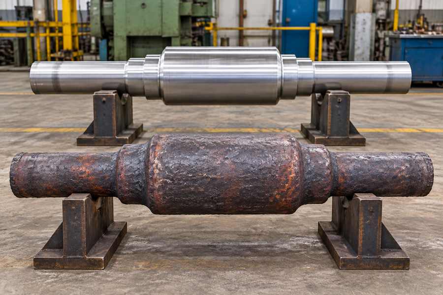
Once the workpiece reaches suitable overall proportions, forging concentrates on developing the required local cross-sections, shoulders, and transitions.
Stepped shafts contain sections of different diameters along a common axis. Their geometry may accommodate bearings, gears, couplings, or other mechanical assemblies.
Flat dies can progressively reduce selected areas, while V-dies and other simple forming tools assist with particular profiles or sectional shapes.
For example, a shaft blank may retain a larger central section while its ends undergo additional drawing. The resulting profile approaches the specified stepped geometry.
The forging sequence establishes where material remains and where it is redistributed. Shoulder positions, intermediate diameters, and transition lengths are monitored as shaping progresses.
Abrupt section changes can increase the risk of folds or unfavorable material flow. Suitable transition geometry and controlled bite placement help produce workable profiles.
Additional material is retained around critical features for subsequent machining. The forged shoulder therefore need not have the sharp profile or final position required on the finished drawing.
Boberry Machining’s forged shafts include straight and stepped configurations, illustrating the range of shaft geometries that may require different forging sequences.
Step 7: Reheat and Continue Forging as Required
The workpiece loses heat during compression, rotation, handling, and exposure to the surrounding environment. Eventually, its temperature may become unsuitable for further planned deformation.
Reheating restores appropriate forming conditions. It may occur between drawing passes, before shaping a stepped section, or during another intermediate production stage.
Operators check the relevant temperature condition before continuing. Repeated heating also requires attention to oxidation, surface condition, and the material’s permitted thermal exposure.
Reheating is therefore part of the deformation sequence rather than a fixed operation performed only after shaping is complete.
Step 8: Apply Controlled Cooling After Forging
Following the final hot-deformation operation, the forging cools under conditions selected for its material grade, section size, and subsequent processing requirements.
Cooling influences microstructural transformations, hardness, residual stresses, and dimensional stability. Uneven temperatures within a component can cause different regions to contract at different rates, potentially resulting in distortion.
Depending on the material and specified route, cooling may involve controlled furnace conditions, insulated surroundings, or another approved method.
A cooling procedure that works for one steel grade may be inappropriate for another. Production records identify the intended conditions and any relevant temperature observations.
Step 9: Perform the Required Heat Treatment
Heat treatment establishes or adjusts the metallurgical condition needed for subsequent machining and service. Its selection depends on material composition, component dimensions, and specified properties.
Annealing may improve machinability or modify hardness and microstructure. Normalizing can establish a desired steel microstructure under suitable conditions.
Quenching followed by tempering may be specified where a particular combination of strength and toughness is required. Not every steel grade receives the same treatment.
Carbon steels, alloy steels, and different stainless steel families have distinct thermal processing requirements. Section thickness also influences heating uniformity and cooling response.
The heat-treatment specification establishes temperature, holding conditions, cooling procedure, and required verification. Relevant furnace records support confirmation of the actual processing history.
Some components also require intermediate thermal treatment. The sequence of treatment, rough machining, and final machining must therefore follow the agreed manufacturing plan.
Step 10: Rough Machine the Forged Component
Rough machining removes excess stock and establishes usable reference surfaces. Operations may include turning, milling, boring, or other machining methods suited to the forged geometry.
For a shaft, turning can establish preliminary diameters and reference surfaces for subsequent inspection. Sufficient material remains for finishing and any necessary dimensional correction.
Machining may expose discontinuities concealed beneath the original forged surface. Newly visible indications are evaluated against the applicable acceptance requirements before work continues.
Machining allowances must account for expected distortion, heat-treatment effects, and final surface requirements. Excessive stock increases machining work, while insufficient stock risks rejection.
A rough-machined forging is not automatically a finished component. Critical tolerances, surface finishes, and functional features are established through the specified finishing operations.
Step 11: Inspect the Forging and Verify Its Requirements
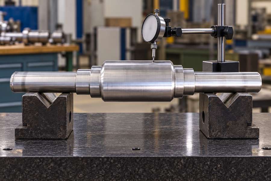
Inspection verifies whether the forging meets its defined dimensional, material, and quality requirements. Checks occur at relevant stages rather than only before shipment.
Dimensional examination may cover overall length, sectional diameters, straightness, and available machining stock. More detailed measurements follow the geometry and delivery condition.
Visual examination identifies surface cracks, laps, folds, and handling damage. When visual checks are insufficient to assess surface integrity, additional nondestructive testing methods may be required.
Ultrasonic testing can assess applicable internal regions for reportable indications. For each component, the inspection requirements must specify the testing technique, areas to be examined, detection sensitivity, and acceptable limits.
Mechanical testing may include tensile, impact, or hardness requirements. Test specimens and their locations must represent the specified acceptance arrangement rather than arbitrary sampling positions.
Final documentation can include material identification, chemical analysis, heat-treatment records, dimensional results, and required inspection reports. These records connect the delivered component to its manufacturing history.
The following table summarizes practical controls and verification methods across the production sequence.
| Manufacturing Stage | Key Process Control | Potential Problem | Verification Method |
| Material preparation | Starting stock and traceability | Incorrect grade or unsuitable stock | Material identification and records |
| Heating | Temperature and uniformity | Uneven deformation or overheating | Heating records and temperature checks |
| Descaling | Surface cleanliness | Entrapped scale or surface damage | Visual examination |
| Upsetting | Alignment and compression sequence | Barreling, buckling, or cracking | Dimensional and surface checks |
| Drawing out | Bite overlap, rotation, and advancement | Uneven sections or bending | Section measurements and straightness checks |
| Profile shaping | Shoulder positions and allowances | Undersized sections or folds | Intermediate dimensional checks |
| Cooling | Material-specific cooling procedure | Distortion or cracking | Cooling records and inspection |
| Heat treatment | Thermal cycle and material condition | Incorrect properties | Furnace records and specified tests |
| Machining and inspection | Remaining stock and acceptance criteria | Dimensional or material nonconformity | Dimensional reports and required NDT |
What Shapes Can Be Produced Through Open Die Forging?
Straight and Stepped Shafts
Straight shafts are produced by progressively developing an elongated workpiece with a relatively consistent cross-section. Controlled advancement and rotation help maintain the intended profile.
Stepped shafts require selective reduction along different regions. Their manufacturing plans must consider shoulder locations, transitions, machining allowances, and straightness.
Both configurations may serve rotating machinery, power transmission equipment, and industrial mechanical assemblies. Final dimensions and functional surfaces depend on subsequent machining.
Forged Blocks and Discs
Blocks can be formed through suitable upsetting and progressive shaping operations. The deformation route determines how material is distributed toward the required rectangular or other simple profile.
Discs generally require controlled upsetting to increase diameter while reducing height. Their dimensions and surface condition are subsequently adjusted through machining.
In both cases, starting-stock volume and deformation history influence the available machining allowances and the ability to achieve the specified finished geometry.
Hollow Components and Rings
Some hollow components can be produced through piercing, boring, or mandrel forging. These operations introduce additional tooling, handling, and dimensional control requirements.
Large rings may instead follow a separate ring-rolling route, where a hollow preform is progressively expanded and shaped.
Mandrel forging and dedicated ring rolling are distinct processes. The correct route depends on ring dimensions, material requirements, and the intended final configuration.
What Should Engineers and Buyers Specify for Open Die Forgings?
Material and Dimensional Requirements
Procurement begins with a complete drawing and material specification. The supplier needs the intended alloy grade, applicable standard edition, service conditions, and required component geometry.
Critical dimensions, machining allowances, and the delivery condition must be clear. A rough-machined blank and a fully finished shaft involve different manufacturing responsibilities.
For stepped shafts, identify bearing locations, shoulder transitions, relevant geometric tolerances, and surfaces requiring final machining. These details influence stock allocation during forging.
Where grain-flow orientation or particular mechanical properties matter, the requirements must be communicated before selecting starting stock and planning deformation.
Heat Treatment and Quality Acceptance
Material specifications alone may not fully define the required heat-treatment condition. Buyers should establish the intended delivery properties and applicable testing arrangements.
Specify relevant mechanical tests, specimen locations, and acceptance criteria. Requirements for thick sections or critical service components may differ from those for general-purpose forgings.
Nondestructive examination instructions should identify the method, examination extent, applicable procedure, and acceptance standard. An unspecified request for defect-free material is not measurable.
Agree on material certificates, heat-treatment records, dimensional inspection reports, and other required documents before manufacturing begins.
Manufacturing Route and Supplier Confirmation
The supplier should review whether the proposed component is suitable for open die forging or requires another forming method.
Starting-stock availability, intended deformation sequence, machining allowances, and necessary inspections all influence manufacturing feasibility.
For ingot-based production, clarify any required discard practices and their effect on material yield. For billet-based production, confirm the relevant preparation requirements separately.
Buyers evaluating Boberry Machining’s forging services can use the following checklist to establish the information needed for technical quotation and acceptance.
| Requirement | Buyer-Supplied Information | Supplier Confirmation | Acceptance Record |
| Material | Grade and applicable standard | Starting-stock suitability and traceability | Material certificate |
| Component geometry | Drawing and critical dimensions | Forging route and machining allowances | Approved drawing and dimensional report |
| Delivery condition | As-forged, rough-machined, or finished | Included processing operations | Inspection and delivery records |
| Heat treatment | Required condition and properties | Proposed treatment sequence | Heat-treatment records |
| Mechanical testing | Tests and specimen locations | Sampling and testing arrangements | Mechanical test report |
| Nondestructive testing | Method, coverage, and acceptance criteria | Examination procedure and timing | NDT report |
| Dimensional inspection | Tolerances and inspection points | Measurement method and stage | Dimensional inspection report |
| Traceability | Identification and documentation requirements | Material tracking arrangements | Traceability records |
Before releasing an order, confirm which operations are included in the quotation and which inspections require separate agreement. This prevents discrepancies between manufacturing scope and acceptance expectations.
The final purchase specification should connect the drawing, material grade, manufacturing route, delivery condition, testing requirements, and documentation into one consistent set of acceptance criteria.