
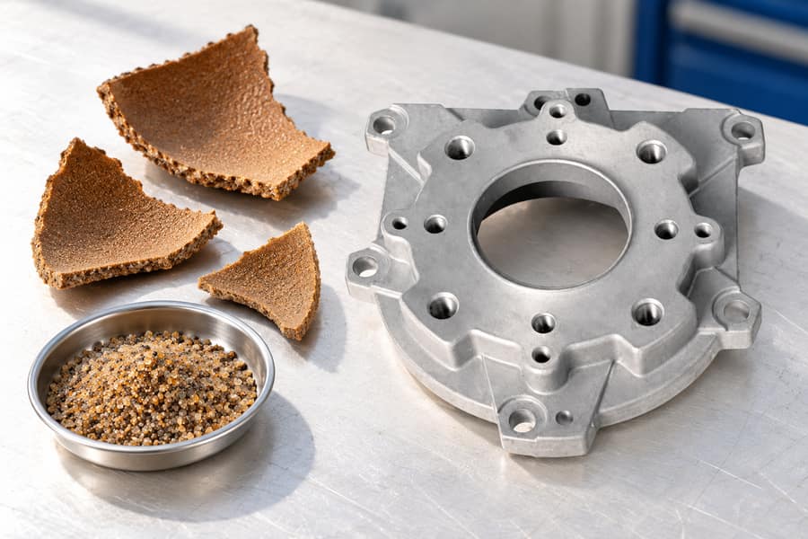
Shell mold casting forms rigid, expendable molds by curing resin-coated sand against heated metal patterns. The reusable tooling is a heated metal pattern, rather than a disposable wax form surrounded by layers of ceramic material.
Selection depends on alloy, part geometry, tooling, inspection needs, and production volume. Review the process, design details and intended application before choosing a production route.
What Is Shell Mold Casting?
The casting cavity takes shape when resin-bonded sand hardens against a heated pattern, creating a relatively thin mold that can withstand subsequent metal pouring.
These shells are produced by curing resin-coated sand against heated metal patterns.
After curing, the shells are removed from the patterns, assembled, and filled with molten metal. The sand mold is broken away after solidification, while the metal patterns remain available for subsequent production.
How Shell Mold Casting Works
The process relies on a thermosetting resin binder that hardens when exposed to the heated pattern. This creates a self-supporting sand shell that reproduces the pattern surface.
Shell thickness depends on factors including pattern temperature, contact time, sand composition, and binder characteristics. These parameters must be controlled to maintain adequate mold strength and dimensional consistency.
Unlike conventional green sand molding, which forms molds by compacting moist sand mixtures, shell molding develops rigidity through resin curing. Both methods generally use expendable molds.
Shell Mold Casting vs. Investment Casting
Although both methods involve expendable molds, their pattern materials and shell formation processes differ substantially.
Each molding cycle begins with a heated metal pattern that activates the sand’s resin binder, allowing the hardened shell to be removed while preserving the pattern for reuse.
The resulting sand shells are assembled into molds without sacrificing the original patterns.
By comparison, investment casting uses expendable wax patterns surrounded by ceramic refractory layers. The wax is removed before molten metal enters the ceramic cavity.
Investment casting can accommodate intricate features and complex shapes, while shell molding provides an alternative for components compatible with reusable patterns and resin-bonded sand molds.
Neither process automatically guarantees better dimensional accuracy, lower cost, or higher mechanical strength.
Engineers must assess these results against the specified alloy and part design, supported by production controls and inspection evidence rather than assumptions about the casting method.
From Heated Pattern to Finished Casting: The Shell Molding Sequence
Production begins by preparing heated tooling and forming cured sand shells, which are assembled before pouring and subsequently broken away to release the casting for finishing.
Each operation affects the final casting’s dimensional consistency, surface condition, and internal soundness.
Step 1 – Metal Pattern Preparation
Manufacturing begins with reusable metal patterns representing the required casting geometry. The pattern design must account for metal shrinkage, draft angles, parting surfaces, and machining allowances.
Patterns are commonly produced from materials capable of withstanding repeated heating and shell removal. Their thermal stability and surface condition influence mold repeatability.
Before molding, the patterns are heated to the temperature required by the selected resin-coated sand system. Suitable release agents may also be applied to assist shell removal.
Step 2 – Resin-Coated Sand Application
Prepared resin-coated sand is brought into contact with the heated pattern, often using a shell molding machine that distributes sand across the pattern surface.
Heat activates the thermosetting binder, bonding neighboring sand grains together. The sand closest to the pattern hardens first, gradually forming the shell.
After the required contact period, excess uncured sand is removed. The remaining shell must be thick enough to withstand handling, assembly, and the intended pouring conditions.
Shell thickness is controlled through the molding parameters rather than assumed to be uniform across every geometry. Recesses and complex surfaces require particular attention.
Step 3 – Shell Curing and Removal
The partially formed shell undergoes sufficient curing to develop the required mechanical strength. Depending on the binder system, additional heating may be necessary.
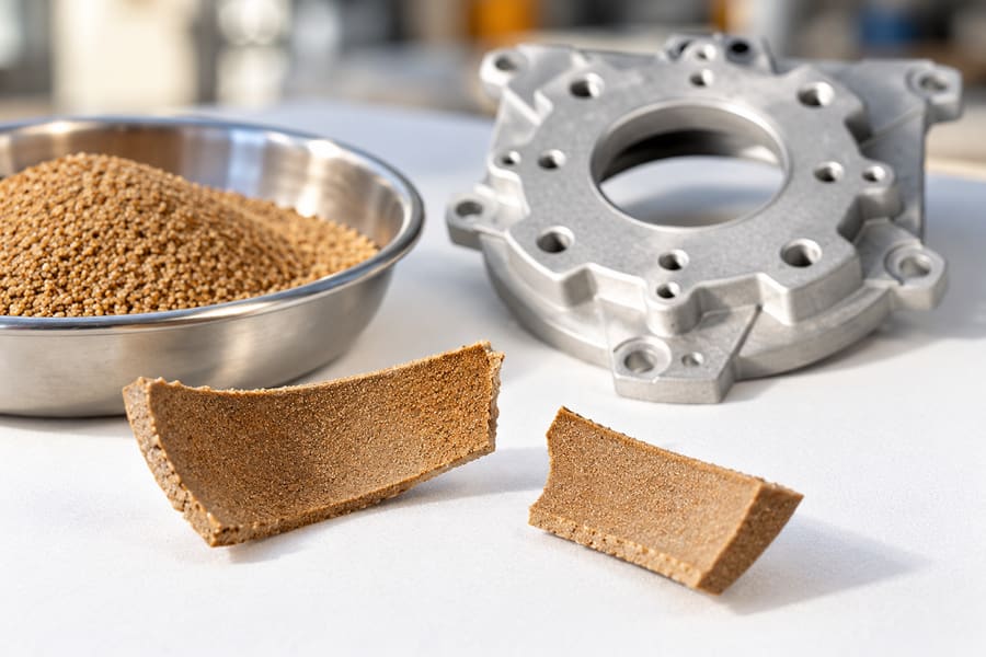
Once curing is complete, the rigid shell is separated from the reusable metal pattern. This operation requires suitable draft and controlled handling to avoid damage.
Operators inspect the shell for cracks, incomplete curing, distortion, or damaged edges. Defective shells can cause metal leakage, cavity distortion, or surface defects during pouring.
Step 4 – Mold Assembly and Core Placement
Two complementary shell halves are normally aligned to create the casting cavity. Their mating surfaces must fit correctly to minimize mold mismatch and metal leakage.
For components containing internal passages, separately manufactured cores can be positioned within the assembled mold. Core location must remain stable throughout pouring and solidification.
The mold design also incorporates suitable gating, risers, and vents. Depending on the shell geometry and pouring conditions, external support or backing material may be necessary.
Step 5 – Molten Metal Pouring and Solidification
The selected alloy is melted and prepared according to its chemical composition and metallurgical requirements. Melt quality must be controlled before pouring.
Molten metal enters the shell cavity through the gating system. Proper filling requires coordinated control of fluid flow, heat loss, venting, and metal delivery.
During solidification, different casting sections cool at different rates. Risers and other feeding provisions help accommodate shrinkage where the alloy and geometry require them.
A rigid shell can help preserve cavity geometry, but it cannot prevent every casting defect. Inadequate feeding, poor venting, or unsuitable pouring conditions may still cause rejection.
Step 6 – Shell Removal and Casting Finishing
After sufficient cooling, the expendable sand shell is broken away to release the casting. Remaining core sand is removed from accessible internal passages.
The casting then undergoes cleaning, gate and riser removal, and necessary surface finishing. Heat treatment may also be specified according to material and service requirements.
Precision features often require additional machining. Bearing seats, threaded holes, sealing faces, and mounting interfaces are common examples where as-cast dimensions may be insufficient.
Final inspection verifies that the component meets its agreed dimensional, surface, material, and functional requirements before acceptance.
What Are the Benefits and Limitations of Shell Mold Casting?
Shell mold casting offers advantages in surface reproduction, mold rigidity, and production repeatability. However, these benefits must be evaluated against tooling investment, material behavior, and manufacturing constraints.
Improved Surface Finish and Dimensional Consistency
Resin-coated sand can create relatively smooth mold cavity surfaces, reducing certain surface irregularities associated with coarser conventional sand molds.
Reusable metal patterns also support consistent cavity formation. When heating, curing, and assembly conditions remain controlled, successive molds can reproduce the intended geometry more reliably.
However, final dimensions still depend on solidification shrinkage, shell movement, mold alignment, and cooling conditions. Critical tolerances should be verified through representative casting trials.
Detailed Geometry and Production Repeatability
Shell molding can reproduce relatively thin sections, defined edges, and detailed external features when the selected alloy fills the cavity successfully.
Internal passages can also be created using cores. Nevertheless, complicated undercuts, inaccessible cavities, and difficult core removal can restrict design freedom.
For recurring production, reusable patterns and controlled curing cycles support repeatable molding operations. This can make shell casting attractive when production quantities justify the tooling.
Improved as-cast surfaces may reduce cleaning or machining on noncritical areas, although precision functional features often require additional material removal.
Tooling Investment and Production Constraints
Metal patterns require accurate manufacturing and sufficient durability for repeated thermal cycling. Their initial cost must be considered alongside expected production quantities.
Shell thickness, casting weight, mold support, and handling equipment also affect feasible component dimensions. Large or heavy castings may demand alternative molding arrangements.
Production economics should account for tooling, sand consumption, core manufacturing, pouring yield, finishing, inspection, and rejected castings rather than comparing pattern costs alone.
Resin Handling and Process Limitations
Resin-coated sand requires controlled storage, heating, and curing. Variations in binder characteristics or thermal exposure can influence shell strength and gas generation.
During pouring, binder decomposition can produce gases and other emissions. Appropriate ventilation, exposure controls, and waste management are important operating considerations.
Used shell sand may require reclamation or disposal depending on contamination and available processing equipment. These requirements influence the overall manufacturing workflow.
Shell molding also remains vulnerable to misruns, shrinkage defects, mold cracking, and core displacement. Its advantages do not replace sound casting design and process validation.
Which Ferrous and Nonferrous Alloys Are Suitable for Shell Molding?
Shell mold casting can accommodate selected ferrous and nonferrous alloys. Compatibility depends on pouring conditions, binder performance, mold strength, solidification characteristics, and the foundry’s equipment.
Cast Iron
Gray cast iron is suitable for various machinery housings, covers, and mechanical components where its machinability and vibration-damping characteristics meet the design requirements.
Ductile cast iron may be selected when greater ductility and suitable tensile properties are needed. Its properties depend on graphite structure, matrix condition, and processing.
For either material, engineers must assess wall thickness, feeding behavior, cooling conditions, and the risk of shrinkage or other metallurgical defects.
Cast Steel
Carbon steel and selected alloy steels can be processed using appropriately designed shell molds. These materials may serve mechanical and structural applications requiring specified strength or toughness.
Steel casting introduces demanding thermal conditions, making mold materials, shell strength, and metal feeding particularly important.
Depending on the alloy and application, subsequent heat treatment may be necessary. Mechanical properties and casting soundness must be verified against the specified requirements.
Aluminum Alloys
Suitable aluminum casting alloys offer a lightweight option for housings, covers, and equipment components. Their selection depends on mechanical loads, corrosion conditions, and geometry.
Melt cleanliness, oxide management, feeding, and cooling require attention. A smooth mold surface cannot compensate for defects introduced through unsuitable metal handling.
Thin sections may be achievable, but successful filling depends on the particular alloy, casting layout, and thermal conditions.
Copper-Based Alloys
Selected brass and bronze alloys can be used for industrial components where corrosion behavior, wear characteristics, or other material properties justify their selection.
Fluidity, shrinkage behavior, and melt handling vary considerably among copper-based alloys. One successful alloy application does not establish suitability for the entire material group.
Valve bodies, fittings, and mechanical components are possible applications, provided their geometry and operating requirements match the selected alloy and molding process.
Material Selection Comparison
| Material Group | Illustrative Applications | Main Engineering Considerations |
| Gray Cast Iron | Machinery housings, covers | Machinability, section thickness, service loads |
| Ductile Cast Iron | Brackets, mechanical bodies | Graphite structure, ductility, feeding |
| Cast Steel | Structural and mechanical components | Thermal demands, shrinkage control, heat treatment |
| Aluminum Alloys | Lightweight housings, equipment covers | Melt quality, porosity, cooling behavior |
| Copper-Based Alloys | Valve components, pump parts | Alloy compatibility, corrosion requirements, solidification |
These applications illustrate potential material choices rather than guaranteed production capabilities. The precise alloy, component size, and required properties must be reviewed before selecting shell molding.
What Design Factors Affect Shell Mold Casting Quality?
Good component design addresses both mold manufacturing and metal solidification. A geometry that can be reproduced accurately by the shell may still produce unacceptable casting defects.
Wall Thickness and Section Transitions
Wall thickness influences molten metal flow, solidification behavior, and feeding requirements. Thin sections may cool before filling, while heavy sections can develop localized shrinkage defects.
Abrupt thickness transitions create uneven thermal conditions. Gradual changes and suitable fillets can improve casting behavior, although their dimensions require alloy-specific evaluation.
Designers should review the complete component rather than isolated features. Gating position, riser placement, and adjacent sections can change the behavior of an otherwise acceptable wall.
Draft Angles and Parting Line Design
Draft angles help cured sand shells separate from reusable metal patterns without damaging cavity surfaces or fragile features.
The required draft depends on pattern geometry, surface condition, shell properties, and removal direction. No single angle is suitable for every component.
Parting line placement also affects mold assembly, external appearance, and dimensional consistency. Poor positioning may create difficult alignment features or unnecessary finishing operations.
Complex undercuts should be reviewed early because they may require modified patterns, additional cores, or another casting method.
Core Design and Internal Passages
Cores create internal passages, recesses, and hollow sections that cannot be formed directly by the external shell halves.
Core strength and positioning must withstand assembly and molten metal forces. Inadequate support can lead to dimensional errors, displaced passages, or core-related inclusions.
Designers should also consider venting and sand removal. Long, narrow, or enclosed passages may complicate cleaning and internal inspection.
Core prints, accessible openings, and suitable support arrangements should be coordinated with the overall mold and gating design.
Common Casting Defects and Their Causes
Shell molds can produce defects originating from the sand system, molten metal, solidification behavior, or mold assembly.
- Gas porosity: May result from binder gases, insufficient venting, dissolved gases, or unsuitable metal handling.
- Shrinkage porosity: Develops when solidifying regions lack sufficient liquid metal feeding.
- Misruns: Occur when metal solidifies before completely filling the cavity.
- Mold-related defects: Include shell cracking, erosion, mismatch, and displaced core features.
These defects cannot always be diagnosed from external appearance. Section examination, suitable nondestructive testing, or metallurgical analysis may be needed to establish their causes.
Corrective actions should address the specific mechanism rather than adjusting pouring temperature, gating, or binder conditions without supporting evidence.
Machining and Final Inspection
Shell molding can reduce finishing requirements for certain surfaces, but important functional interfaces often need secondary machining.
Bearing bores, sealing faces, threaded holes, and precision mounting features require tolerances determined by the final assembly, not simply the casting method.
Dimensional checks should be combined with material verification and relevant defect inspections.
Inspection plans may require hardness measurements to assess material condition, mechanical tests to verify specified properties, or nondestructive methods to investigate internal and surface discontinuities.
Inspection requirements should be agreed upon before production so machining allowances, accessible test surfaces, and acceptance criteria can be incorporated into the design.
What Are the Industrial Applications of Shell Mold Casting?
Shell mold casting is applicable to selected industrial components requiring repeatable geometry, suitable material properties, and controlled surface quality. The final process choice depends on detailed component requirements.
Pump and Valve Components
Valve bodies, pump housings, and related fluid-handling parts are potential applications, particularly when internal passages can be formed using appropriately supported cores.
These components often require machined sealing interfaces, controlled internal geometry, and suitable corrosion resistance. Pressure-containing designs also require qualified materials and defined integrity testing.
A casting’s external appearance does not establish its pressure capability. Internal soundness, wall thickness, material properties, and inspection results must support the intended operating conditions.
Gearbox and Transmission Housings
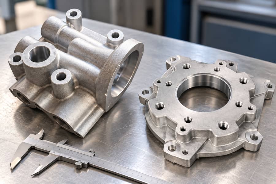
Gearbox housings and transmission enclosures benefit from consistent external geometry and controlled internal cavities, especially when multiple mounting features must align.
Shell molding can provide a repeatable starting shape, while machining establishes precision bearing seats, shaft locations, and mating surfaces.
Casting distortion, wall thickness, and machining datum selection must be considered together. Accurate external surfaces alone do not guarantee alignment after finishing.
Automotive and Machinery Components
Selected brackets, levers, mechanical bodies, and engine-related components can be considered for shell mold casting when their geometries and materials are compatible.
Mechanical requirements vary substantially. Components subjected to cyclic loading need appropriate fatigue assessment, while highly loaded parts may require additional metallurgical examination.
Material selection, heat treatment, and casting quality should be evaluated together. No casting method independently guarantees the strength required by a particular component.
Industrial Equipment and Structural Parts
Equipment covers, machine supports, mounting bodies, and mechanical brackets represent further potential applications for resin-sand shell molding.
Recurring production of detailed shapes may justify reusable metal patterns, particularly when surface quality and repeatability influence downstream manufacturing.
Boberry Machining’s catalog of cast components provides examples of industrial casting categories. Component listings should be assessed separately from the specific molding process used to manufacture them.
For each application, engineers should verify casting dimensions, material compatibility, mechanical requirements, and available production routes before approving a manufacturing process.
How Do You Choose Shell Mold Casting for Your Components?
Selecting a casting process requires more than comparing surface finish or tooling investment. Material compatibility, component complexity, production quantity, and inspection requirements determine practical suitability.
Shell Mold Casting vs. Other Casting Methods
Conventional green sand casting uses compacted sand molds and can accommodate a wide range of component sizes and production arrangements.
Shell molding uses resin-coated sand and heated patterns, potentially improving surface reproduction and repeatability, but introducing additional tooling and binder-processing considerations.
Ceramic-shell investment casting follows a different pattern and mold-making sequence. It may suit intricate geometries that are difficult to release from reusable shell molding patterns.
Pressure die casting uses reusable metal dies and pressure-assisted filling. Its economic suitability often depends on alloy selection, tooling complexity, and production quantity.
The term gravity casting requires particular care. Shell molds are commonly gravity-poured, so gravity filling and shell molding are not mutually exclusive classifications.
However, gravity permanent-mold casting uses reusable metal molds rather than expendable resin-sand shells. Boberry Machining’s gravity casting route can be considered separately when evaluating suitable production alternatives.
| Casting Method | Mold and Pattern Approach | Potential Advantages | Main Selection Constraints |
| Shell Mold Casting | Resin-coated sand cured against heated reusable patterns | Surface reproduction, repeatability | Metal tooling, binder processing, shell limitations |
| Green Sand Casting | Compacted sand mold formed around removable patterns | Flexible component sizes and tooling approaches | Mold rigidity, surface and dimensional requirements |
| Investment Casting | Ceramic shell formed around expendable wax patterns | Intricate shapes and fine details | Pattern production, shell processing, production economics |
| Pressure Die Casting | Pressure-assisted filling of reusable metal dies | Repeatability for suitable high-volume components | Alloy restrictions, die investment, filling-related defects |
The best method depends on the actual design and acceptance criteria. Comparison tables cannot replace supplier-specific process capability assessments or representative sample evaluation.
Evaluate Geometry, Materials, and Production Requirements
Begin with the component drawing, intended alloy, operating conditions, and required mechanical properties. These establish the boundaries for acceptable casting methods.
Review overall dimensions, minimum sections, internal cavities, draft requirements, and features requiring machining. Complex geometries may introduce tooling difficulties that outweigh expected surface benefits.
Expected order quantities also matter. Reusable metal tooling may be economical across recurring orders but difficult to justify for limited production.
Define Quality and Inspection Requirements
Casting quality requirements should distinguish cosmetic appearance, dimensional conformity, material properties, and internal soundness.
Specify critical dimensions, surface requirements, machining allowances, and any pressure or mechanical tests needed for the application.
Where internal defects could affect performance, establish appropriate inspection methods and acceptance limits. Testing should reflect the component’s material, geometry, and service conditions.
Verify Supplier Capabilities Before Production
Suppliers should confirm their available molding methods, supported alloys, maximum practical component dimensions, and tooling arrangements before a casting route is selected.
For a proposed shell molding process, request information about pattern manufacturing, resin-coated sand preparation, shell curing, mold assembly, and relevant inspection capabilities.
Sample castings can then be assessed for dimensional consistency, material conformity, surface quality, and machining behavior. Production release should follow documented verification that the sample castings satisfy the specified dimensional, material, and inspection criteria.
When working with Boberry Machining, buyers can review the relevant casting and machining options against their component drawings, then confirm the specific manufacturing route and qualification requirements before production.