
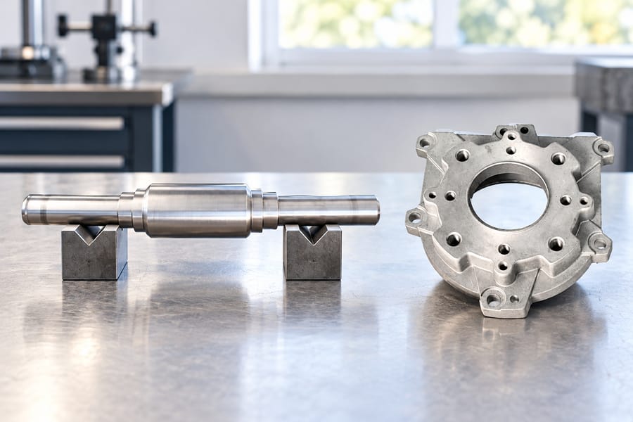
Forged and cast components can exhibit different mechanical properties because their manufacturing processes create distinct material structures. However, neither process guarantees superior strength under every operating condition.
Meaningful comparisons require equivalent alloys, heat treatments, section sizes, and testing conditions. Engineers must also consider fatigue resistance, impact toughness, stiffness, internal defects, and component geometry when selecting a manufacturing process.
How Forging and Casting Influence Material Properties
How Forging Changes Metal Structure
Forging shapes metal through controlled plastic deformation, typically using compressive forces. Depending on the alloy and processing conditions, deformation can alter grain structure, improve material consolidation, and influence mechanical properties.
During forging, metal flows into the required geometry. This movement can create directional grain-flow patterns that influence how the component responds to tensile, bending, and cyclic loads.
For forged parts, the relationship between deformation direction and finished geometry deserves particular attention. Favorable grain alignment may improve performance along certain loading directions without providing equal benefits in every orientation.
Forging temperature, deformation magnitude, and subsequent heat treatment also affect the resulting microstructure. Poorly controlled processing can introduce discontinuities or produce properties that fail to meet specification.
How Casting Forms Metal Structure
Casting produces components by pouring or introducing molten metal into a mold, where it solidifies into the required geometry. Solidification behavior largely determines the initial microstructure.
Cooling rates vary with section thickness, mold characteristics, and local geometry. These differences can influence grain morphology, segregation, and the distribution of mechanical properties throughout a casting.
Shrinkage cavities, gas porosity, and inclusions may develop when solidification or melt handling is insufficiently controlled. Their presence and severity depend on material composition and manufacturing conditions.
Proper process design, feeding, solidification control, and heat treatment can improve casting quality. A sound casting should be evaluated against specified properties rather than assumed to be mechanically inferior.
Why Manufacturing Method Alone Does Not Determine Strength
Strength depends on the combined effects of alloy composition, microstructure, heat treatment, defects, and operating conditions. Manufacturing method influences these factors but does not determine performance independently.
A properly manufactured steel casting may satisfy demanding structural requirements, while a forging containing harmful laps or cracks may fail. Process selection therefore requires material-specific evidence.
What Makes a Fair Forged vs Cast Strength Comparison?
Compare Equivalent Materials and Heat Treatments
A meaningful comparison starts with equivalent alloy compositions and comparable material specifications. Comparing forged alloy steel with a different cast iron grade cannot isolate manufacturing-process effects.
Heat treatment introduces another variable. Normalizing, quenching, tempering, and annealing can substantially change strength, hardness, ductility, and toughness, even when the starting chemical composition is similar.
Engineers should compare the actual specified material conditions, not simply the names of the manufacturing processes. Equivalent chemistry alone does not guarantee equivalent microstructure or properties.
Account for Section Thickness and Material Orientation
Section thickness affects cooling behavior during casting, forging, and subsequent heat treatment. Thick sections may exhibit different core properties from thinner regions or surfaces.
Mechanical properties can also depend on orientation. A forged component may show different longitudinal and transverse properties because its deformation history produces directional microstructural characteristics.
Test specimens should represent comparable section sizes and locations. Otherwise, differences attributed to forging or casting may actually reflect cooling conditions, specimen orientation, or local material quality.
Use Equivalent Testing Conditions
Tensile, impact, and fatigue results must be compared using consistent testing procedures. Specimen geometry, preparation, temperature, loading rate, and applicable standards influence measured results.
Standard material coupons provide useful evidence of material properties, but they do not reproduce every feature of a finished component.
A component’s shape, surface finish, and stresses retained from manufacturing can affect its behavior under load.
Comparing a forged shaft with a cast housing is not a controlled strength comparison. Their different geometries, stress distributions, and service functions prevent direct attribution of performance differences to manufacturing method.
How Forging and Casting Influence Load-Bearing Performance
Evaluating Resistance to Fracture and Permanent Deformation
When a metal specimen is pulled under increasing force, its tensile strength helps establish the maximum stress it can carry during the test.
When reviewing material test reports, purchasers should check that the recorded ultimate tensile strength meets the specified material requirement, without treating that value as the finished component’s allowable load.
Engineers use yield strength to assess the risk of lasting shape changes under load, with the reported limit determined by the specified yield-point or proof-stress method.
Engineers use it to evaluate whether components can withstand service loads without unacceptable permanent dimensional changes.
Forged metals may exhibit favorable tensile and yield properties because of their processing history. However, alloy composition, heat treatment, specimen orientation, and internal soundness determine the actual results.
Sound cast steel can achieve tensile and yield properties comparable to specified forged steel grades. Such comparisons remain valid only when material conditions and testing requirements are appropriately matched.
Fatigue Strength and Resistance to Cyclic Loading
Fatigue failure develops through crack initiation and propagation under repeated loading. Components can experience fatigue damage even when maximum operating stresses remain below their measured tensile strength.
Favorable grain flow may improve fatigue resistance in particular forged components. Surface condition, local stress concentrations, inclusions, and preexisting discontinuities also influence crack development.
Casting porosity can reduce fatigue performance when defects occur near highly stressed regions. Forging laps, cracks, or unfavorable surface conditions can create similar fatigue concerns.
Fatigue comparisons must consider stress amplitude, loading direction, mean stress, operating environment, and expected cycle count. A single tensile test cannot establish fatigue life.
Impact Toughness and Fracture Behavior
Impact toughness describes energy absorption under specified rapid-loading test conditions. It provides information about fracture behavior but should not be treated as interchangeable with tensile strength.
Material composition, microstructure, temperature, and internal discontinuities influence impact performance. Some materials retain useful toughness at lower temperatures, while others become more susceptible to brittle fracture.
Forging may provide favorable impact properties through suitable microstructural development. Properly processed cast steel can also exhibit useful toughness, depending on grade, heat treatment, and soundness.
Impact test results should identify specimen orientation, notch configuration, and testing temperature. Values measured under different conditions may not provide a reliable comparison.
Stiffness and Resistance to Elastic Deformation
Stiffness describes resistance to elastic deformation under load. Unlike yield strength, it concerns deflection before permanent deformation occurs.
For equivalent steel alloys, the elastic modulus generally remains similar whether the material is forged or cast. Differences in component geometry can have a much greater influence on overall stiffness.
A component with properly designed ribs or sectional dimensions may resist deflection effectively without requiring a manufacturing process associated with higher material strength.
Table 1: Forged vs Cast Parts — Mechanical Property Comparison
| Mechanical property | Forged part considerations | Cast part considerations | Evaluation method |
| Tensile strength | Alloy, deformation history, heat treatment | Alloy, solidification quality, heat treatment | Tensile testing |
| Yield strength | Material condition and orientation | Material condition and soundness | Yield or proof-strength testing |
| Fatigue resistance | Grain orientation, surface condition, discontinuities | Porosity, inclusions, surface condition | Representative fatigue testing |
| Impact toughness | Microstructure, temperature, orientation | Microstructure, temperature, defects | Impact testing |
| Stiffness | Elastic modulus and component geometry | Elastic modulus and component geometry | Deflection analysis or testing |
How Grain Flow and Manufacturing Defects Affect Strength
Directional Grain Flow in Forged Components
Metal deformation during forging can create grain-flow patterns following the component’s geometry. These patterns may contribute to favorable mechanical behavior when aligned with important service loads.
However, grain flow does not automatically follow every principal stress direction. Complex loading conditions may place different regions of a component under competing tensile, bending, or torsional stresses.
Directional properties can also introduce anisotropy, meaning mechanical behavior varies with orientation. Engineers should evaluate whether the actual grain-flow pattern supports the intended loading conditions.
Casting Discontinuities That Can Affect Strength
Casting discontinuities can arise from melt quality, mold configuration, metal flow, insufficient feeding, or conditions during solidification. Their mechanical significance depends on size, distribution, and location.
- Shrinkage porosity: Cavities caused by insufficient feeding during solidification can reduce effective load-bearing area and create local stress concentrations.
- Gas porosity: Entrapped or dissolved gases may produce internal voids that affect mechanical integrity, particularly under cyclic loading.
- Inclusions: Nonmetallic particles or foreign materials can interrupt the metal matrix and contribute to localized crack initiation.
- Hot tears and cold shuts: Solidification stresses or incomplete fusion between metal streams can produce discontinuities that compromise component integrity.
Finding an internal or surface irregularity does not necessarily mean the casting must be rejected. Acceptance depends on its characteristics, applicable material specifications, and the stresses expected in service.
Common Forging Defects
Forging can improve material consolidation under suitable conditions, but deformation also introduces manufacturing risks. Tooling, temperature, material flow, and starting stock quality require appropriate control.
- Laps and folds: Improper metal flow can create folded surface layers that behave as discontinuities under loading.
- Forging cracks: Excessive deformation or unsuitable processing conditions can produce fractures that reduce mechanical reliability.
- Incomplete die filling: Insufficient material flow can leave required geometric features improperly formed.
- Residual internal defects: Some discontinuities from the starting material may remain after forging, while others can develop during processing.
A forged component should therefore undergo inspection appropriate to its material and service requirements. Forging alone does not establish structural integrity or eliminate every defect.
Why Defect Location Matters
Defects near highly stressed surfaces, sharp transitions, or critical load paths may be more damaging than similar defects elsewhere. Local stress concentration often determines their significance.
Defect acceptance must consider size, orientation, loading conditions, and relevant specifications. Inspection findings should be assessed against defined engineering criteria rather than appearance alone.
Why Cast Steel and Cast Iron Must Be Compared Separately
Mechanical Properties of Cast Steel
Cast steel and forged steel can belong to comparable alloy families, allowing meaningful comparisons when chemistry, processing condition, section thickness, and test requirements are appropriately controlled.
Cast steel properties depend on solidification quality, heat treatment, and microstructure. Properly produced material can provide combinations of strength, ductility, and toughness suitable for structural service.
However, meeting a tensile-strength requirement does not establish identical fatigue or impact performance. Those properties require separate evaluation under relevant conditions.
Mechanical Properties of Cast Iron
Cast iron differs from cast steel in carbon content and microstructural characteristics. Graphite morphology can significantly influence tensile behavior, fracture characteristics, damping, and ductility.
Gray cast iron contains graphite flakes that contribute to useful damping characteristics but also influence tensile strength and crack behavior. It commonly exhibits limited tensile ductility.
Ductile cast iron contains predominantly spheroidal graphite, which generally supports greater ductility than gray iron. Actual mechanical properties still depend on matrix structure, grade, and heat treatment.
Why Material Classification Changes the Comparison
Comparing forged steel directly with cast iron introduces differences beyond the manufacturing process. Material composition and graphite structure may dominate the observed mechanical behavior.
Engineers should compare specified grades against application requirements. A universal ranking of forged steel, cast steel, and cast iron would overlook important differences in material condition.
How Casting Geometry Can Improve Component Design
Complex Shapes and Internal Passages
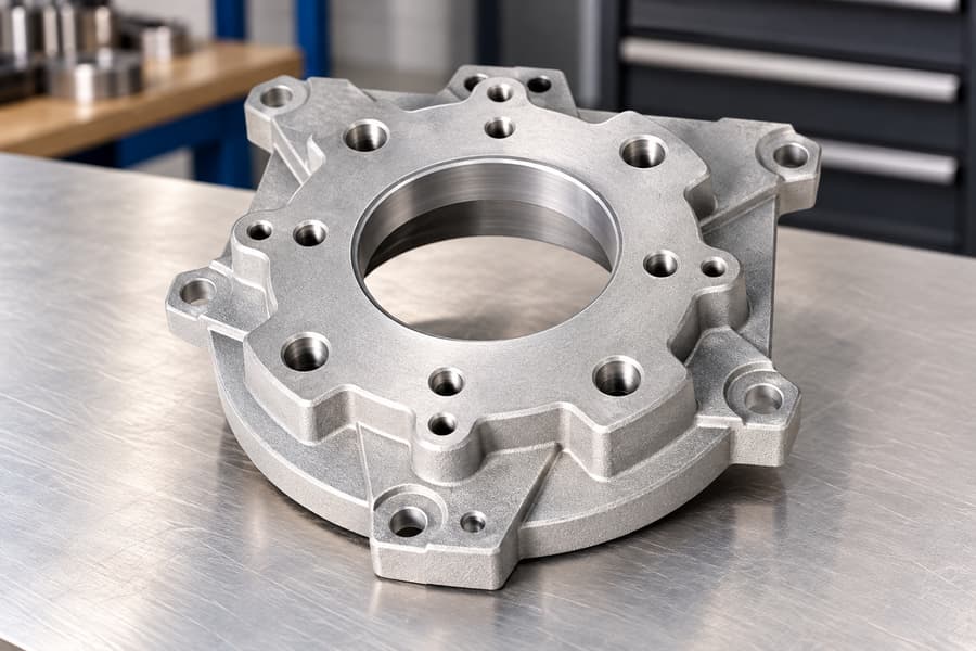
Casting can produce complicated external shapes and internal cavities that would be difficult to manufacture from forged blanks. Cores and suitable mold designs enable intricate internal passages.
Industrial cast components may include valve bodies, pump housings, and other geometrically complex parts. These applications illustrate casting’s design flexibility, not a universal mechanical advantage.
A casting can also reduce the volume of material requiring removal during subsequent machining. The actual benefit depends on dimensional requirements, casting quality, and production conditions.
Structural Stiffness and Load Distribution
Structural performance depends on geometry as well as material properties. Ribs, wall thickness, cross-sectional shape, and transitions influence stiffness and load distribution.
Casting provides flexibility to incorporate reinforcing features into suitable component designs. These features may help achieve required structural performance without relying solely on higher nominal material strength.
However, abrupt section changes can create stress concentrations or complicate solidification. Casting design must balance mechanical requirements with feeding, cooling, and manufacturability considerations.
Integrated Components and Reduced Assembly Requirements
Casting can combine multiple features into one component, potentially reducing separate joints, fasteners, and assembly interfaces. This may simplify manufacturing and dimensional coordination.
Integrated geometry does not automatically improve reliability. The finished component must still satisfy requirements for material soundness, structural loading, tolerances, and service performance.
When Should Engineers Choose Forging or Casting?
Applications Where Forging May Be Preferred
Forging may be suitable for components exposed to substantial cyclic loading, directional stresses, or demanding combinations of strength and toughness.
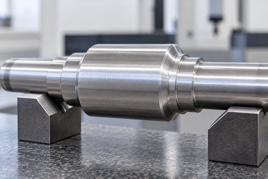
Shafts, connecting elements, and other load-bearing parts may benefit from controlled grain flow when their geometry and loading conditions support that benefit.
For applications involving forged shafts, engineers should evaluate bending, torsion, fatigue requirements, bearing interfaces, and machining tolerances before specifying the manufacturing route.
Material grade, production capacity, tooling feasibility, and inspection requirements must also be considered. Favorable mechanical properties alone cannot justify every forging application.
Applications Where Casting May Be Preferred
Casting may be preferable when component geometry requires internal passages, irregular external surfaces, or integrated features that would otherwise demand extensive machining or assembly.
Valve bodies, equipment housings, and other complex structures often benefit from casting’s geometric flexibility. Their suitability still depends on the specified alloy and verified component performance.
Casting should not be rejected solely because a forged alternative has higher nominal strength. The finished casting may satisfy structural requirements through appropriate material selection and geometry.
Consider Machining and Finished-Part Requirements
Both forged and cast components may require machining to achieve specified tolerances, surface finishes, and functional interfaces. Manufacturing selection should include these downstream requirements.
Machining allowances, datum selection, and critical surface locations influence dimensional control. Surface finishing and machining conditions may also affect fatigue-sensitive regions.
Boberry Machining offers forging, cast parts, and post-machining services. Process selection should be based on drawings, material specifications, manufacturing feasibility, and required verification rather than generalized strength claims.
Table 2: Forging vs Casting — Manufacturing Selection Guide
| Engineering requirement | Forging considerations | Casting considerations |
| High cyclic loading | Favorable grain flow may provide advantages | Requires suitable material and defect control |
| Complex internal passages | May require extensive machining or assembly | Can form complex internal geometry |
| High impact loading | Evaluate toughness and material orientation | Evaluate alloy, heat treatment, and soundness |
| Complex integrated geometry | Depends on forging design and tooling | Supports many integrated shapes |
| Tight dimensional tolerances | Finish machining may be required | Finish machining may be required |
| Critical structural components | Verify properties, defects, and loading direction | Verify properties, defects, and loading direction |
How to Verify Forged and Cast Part Strength Before Production
Establish Material and Mechanical Requirements
Mechanical requirements should be defined before selecting a manufacturing process. Engineering drawings and purchase specifications need to identify the relevant material grade and condition.
Required yield strength, tensile strength, ductility, and heat treatment should be stated where applicable. Fatigue, impact, or fracture-toughness requirements need separate definition when service conditions justify them.
Engineers should also identify loading directions, operating temperatures, environmental exposure, and critical locations. These details determine which material characteristics require verification.
Select Appropriate Testing and Inspection Methods
Different tests answer different engineering questions. A combination of mechanical testing, nondestructive examination, and dimensional inspection may be necessary for critical components.
- Tensile testing: Measures specified tensile properties, including ultimate tensile strength, yield or proof strength where applicable, and ductility.
- Impact testing: Evaluates energy absorption under defined temperature, specimen geometry, and loading conditions.
- Fatigue testing: Examines response to repeated loading using representative stress conditions and appropriate test procedures.
- Nondestructive examination: Uses suitable ultrasonic, radiographic, magnetic particle, or liquid penetrant methods to assess relevant discontinuities.
- Dimensional inspection: Verifies geometric tolerances, machined interfaces, and other features essential to component function.
Inspection methods have different detection capabilities and limitations. Selection should reflect the material, anticipated defects, accessibility, and applicable acceptance specifications.
Define Inspection and Acceptance Criteria
Acceptance criteria must be established before production rather than after defects are discovered. Requirements should define permissible discontinuities, critical inspection regions, and documentation needs.
Sampling plans, test specimen orientation, and examination coverage should match applicable specifications. Material identification and traceability help connect inspection results to the delivered components.
A material certificate confirms only the properties and conditions actually covered by its documentation. It cannot independently establish fatigue life or structural performance under every operating condition.
Validate Performance Under Actual Service Conditions
Validation should represent the component’s expected mechanical loads, operating environment, and important geometric features. Material testing alone may not capture the behavior of the finished part.
For fatigue-sensitive components, surface condition, geometric transitions, loading direction, and internal discontinuities deserve particular attention. Their combined effects can determine where damage first develops and how long the component remains serviceable.
Analytical assessment and representative testing should be compared with defined acceptance requirements. Where uncertainties remain, additional component-level testing may be necessary.
The final manufacturing decision should reflect verified material properties, component geometry, inspection results, and service requirements rather than assumptions about inherent forging or casting superiority.