
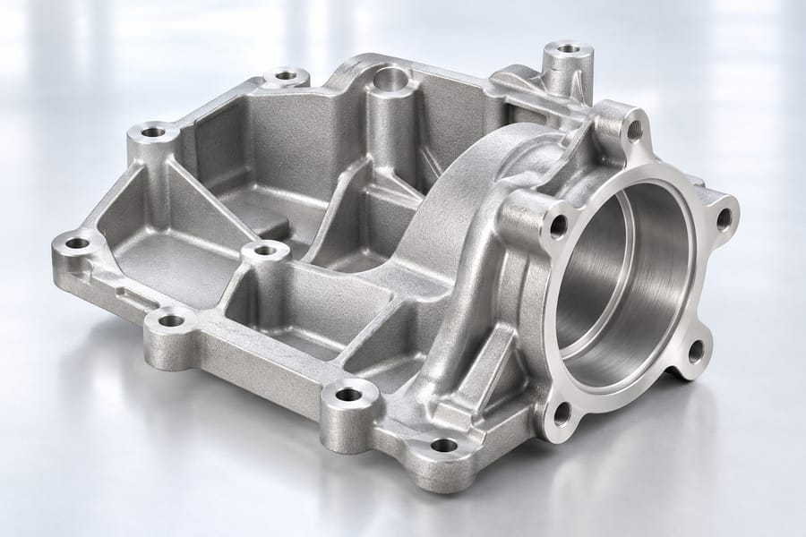
A sound casting design balances service loads with the way molten metal fills a mold and solidifies. Wall thickness, ribs, transitions, internal passages, and machining stock all affect whether the finished component meets its drawing.
Review these features alongside alloy choice, inspection access, tolerances, and production volume before committing to patterns or tooling.
Define Functional Requirements Before Starting the Casting Design
Identify Operating Conditions and Performance Requirements
The first step is to define how the finished component will perform in service. Design decisions should reflect actual loading conditions, environmental exposure, assembly requirements, and the consequences of component failure rather than focusing exclusively on the shape of the casting.
Engineers should document the relevant operating conditions, including static and dynamic loads, operating temperature, pressure, vibration, corrosion exposure, and expected service life. Components subjected to repeated loading may require particular attention to fatigue resistance, while pressure-containing parts demand appropriate consideration of structural integrity and leakage risks.
Environmental conditions also influence material and surface requirements. A component exposed to moisture, chemicals, abrasive particles, or temperature cycling may require different material properties and inspection controls from a similar component operating in a protected indoor environment.
Establish Critical Dimensions and Functional Interfaces
Identify the surfaces and dimensions that determine whether the component fits and functions correctly within the assembly. Typical examples include mounting faces, bearing seats, shaft openings, threaded connections, sealing surfaces, and interfaces with adjoining components.
Distinguish these critical features from external surfaces whose dimensional variation has little effect on performance. This distinction helps establish a realistic tolerance strategy and prevents unnecessary precision requirements from increasing machining, inspection, and production effort.
Define datum references and measurement methods early. A dimension may appear straightforward on a drawing but become difficult to verify if its reference surface is unstable, inaccessible, or inconsistent with the way the component is positioned during machining and assembly.
Separate Essential Requirements From Design Preferences
Every specified feature should have a clear purpose. Decorative contours, unnecessary recesses, and overly complex transitions can increase tooling difficulty without improving structural performance or assembly function.
During the initial review, classify requirements according to their engineering importance:
- Functional requirements: Load capacity, sealing performance, dimensional fit, and other conditions essential to operation.
- Manufacturing requirements: Mold release, metal flow, feeding access, machining accessibility, and feasible production methods.
- Quality requirements: Material properties, surface condition, defect acceptance criteria, and inspection documentation.
- Optional features: Details that can be simplified or removed without compromising the component’s intended use.
This classification provides a practical basis for resolving design conflicts. When a feature increases casting complexity, engineers can evaluate its actual functional value before accepting the additional manufacturing burden.
Select the Appropriate Casting Material and Manufacturing Process
Match Material Properties to the Service Environment
Material selection should begin with the component’s mechanical and environmental requirements. Strength, ductility, toughness, corrosion resistance, wear resistance, thermal properties, and castability must be considered together because improving one property does not necessarily improve the others.
For example, a component exposed to corrosive fluids may require a particular alloy composition and a controlled surface condition. A load-bearing housing may place greater emphasis on strength, stiffness, fatigue performance, and dimensional stability. The correct balance depends on the application and applicable material specification.
Engineers should also evaluate the condition in which the material will be supplied. Heat treatment, cooling history, section thickness, and subsequent machining can influence the properties and dimensional behavior of the finished component. Material selection therefore cannot be separated entirely from the manufacturing route.
Understand Casting Alloy Specifications
Material designations must correspond to the correct product form and governing specification. Cast alloys and wrought alloys may have related chemical compositions, but their manufacturing histories, microstructures, mechanical requirements, and acceptance criteria can differ.
For stainless steel, CF8 and CF8M are cast stainless steel designations commonly associated with austenitic stainless steel families. Wrought grades 304 and 316 belong to related compositional families, but CF8 and CF8M must not be treated as automatic equivalents of wrought 304 and 316.
Before approving a material, verify the applicable standard, chemical composition, mechanical property requirements, heat-treatment condition, corrosion requirements, and any supplementary testing. A familiar grade name alone does not establish that a particular casting meets the application’s requirements.
Match the Casting Process to Part Geometry and Production Needs
Different casting processes offer different combinations of geometry, tooling complexity, dimensional capability, surface finish, production volume, and alloy compatibility. Selecting a process requires evaluating the complete component rather than choosing solely on the basis of nominal material or external shape.
Sand casting can accommodate many component sizes and a broad range of ferrous and nonferrous alloys when the selected foundry process is suitable. Investment casting can support intricate geometries and detailed features, while permanent mold and die casting are commonly associated with compatible nonferrous alloys and specific tooling requirements.
Steel is not suitable for every mold or casting process. Process selection must account for melting temperature, mold materials, tooling durability, thermal behavior, and the requirements of the particular alloy. Die casting, for example, should not be assumed to be an appropriate route for steel components.
When reviewing potential routes, engineers can consult BOBERRY’s casting information as part of the supplier discussion. The selected process still requires confirmation against the component’s geometry, material, dimensions, production volume, and quality requirements.
Evaluate Total Manufacturing Cost
The lowest initial tooling cost does not necessarily produce the lowest total component cost. Tooling, casting yield, finishing, machining, inspection, rejected parts, and production volume all affect the economic result.
A process that produces a more detailed near-net shape may reduce machining but require more specialized tooling. A simpler casting may require additional material removal while offering easier inspection or greater flexibility during design changes. These trade-offs should be evaluated using the same functional and quality requirements.
Optimize Part Geometry, Wall Thickness, and Structural Transitions
Maintain Practical Wall Thickness
Uniform wall thickness is a useful starting principle because it can promote more consistent cooling and reduce the risk of localized hot spots. However, uniformity should not override structural requirements or force an unnecessarily heavy component.
When a section must change thickness, use gradual transitions where feasible, particularly around thick bosses, mounting pads, and structural junctions. Sudden changes can create differences in cooling rates and increase the likelihood of shrinkage defects or distortion. The appropriate transition depends on the alloy, section dimensions, casting process, and structural loading.
Thin sections also require careful evaluation. If a wall is too thin for the selected process and component geometry, molten metal may not fill the mold completely before solidification. Rather than assuming a universal minimum thickness, engineers should confirm the practical limits with the foundry.
Design Ribs, Bosses, and Junctions Carefully
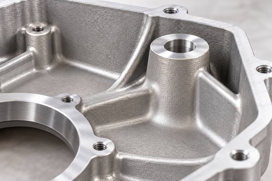
Ribs can improve stiffness without requiring the entire component to have thick walls. Their dimensions and spacing should reflect the applied loads, available casting processes, and the need to avoid creating excessive local mass.
Bosses used for bolts, threaded holes, or mounting features require particular attention. A large boss connected to a thin wall can form a heavy junction that cools more slowly than surrounding sections. This may produce internal shrinkage or require additional feeding measures.
Where possible, reduce unnecessary material around these junctions and use smooth transitions. The design must still provide adequate material for fastener engagement, machining, and local load transfer. Structural calculations or finite element analysis may be appropriate when the component carries significant loads or has demanding fatigue requirements.
Avoid Unnecessary Complexity and Excessive Mass
Deep pockets, narrow channels, undercuts, and intricate internal passages may increase mold or core complexity. They can also make cleaning, machining, and inspection more difficult. Every such feature should have a clear functional justification.
When reviewing a complex shape, ask whether the same function could be achieved through a simpler casting, a machined opening, or an assembly of separate components. An alternative is not automatically better, because joints and additional parts introduce their own cost and performance considerations.
The aim is to balance structural efficiency with reliable manufacturing. Removing unnecessary material may reduce casting mass, but excessively thin sections or abrupt geometry changes can introduce new production risks. Design changes should therefore be evaluated as a complete system rather than in isolation.
Design Parting Lines, Cores, Draft, and Machining Allowances
Position the Parting Line Strategically
The parting line is where the mold sections meet. Its location affects mold construction, the formation of flash, finishing requirements, and the appearance of the casting. Poor placement may also complicate the production of critical surfaces or increase the difficulty of removing the component from the mold.
Whenever practical, position the parting line away from precision sealing faces, bearing interfaces, and other surfaces where irregularities would interfere with function. The preferred location depends on the component shape and selected casting process, so it should be agreed upon during design review rather than treated as a drafting detail.
Consider how the parting line relates to the primary datum scheme. If a critical dimension is measured from a surface affected by mold mismatch or finishing, the resulting variation may complicate dimensional control. A suitable machining strategy can address some of these concerns, provided sufficient material is available.
Plan Cores and Internal Cavities
Cores create internal passages, hollow regions, and other features that cannot be formed directly by the mold cavity alone. Their design influences dimensional accuracy, metal flow, core stability, and the ease of removing core material after casting.
Before specifying a complicated cavity, determine whether it must be cast internally or can be produced through drilling, milling, or another secondary operation. Casting a passage may reduce machining, but it can introduce core-related tolerances and inspection challenges. Machining may offer more direct control over certain dimensions but require tool access and additional material.
Core positioning should also be reviewed at junctions and thin sections. A core that moves or breaks can cause dimensional defects or internal inconsistencies. Where internal geometry is critical, establish appropriate verification methods and discuss process controls with the supplier before approving the final drawing.
Specify Draft Angles and Tooling Allowances
Draft provides the clearance needed to remove a pattern or casting from its tooling, depending on the process. Insufficient draft can complicate removal, damage surfaces, or increase tooling wear. The required angle varies with mold construction, surface depth, material, and geometry.
Draft should be evaluated separately from shrinkage compensation and machining allowance. Shrinkage compensation accounts for dimensional changes during cooling, while machining allowance provides additional material for subsequent operations. These requirements are related to the production route but serve different purposes.
For complex components, agree on draft directions and any affected dimensions with the supplier. A change in draft can alter the finished geometry, particularly around openings, ribs, and deep walls. The drawing should make clear which surfaces are functional and which may follow the natural geometry required for casting.
Allocate Material for Post-Casting Machining
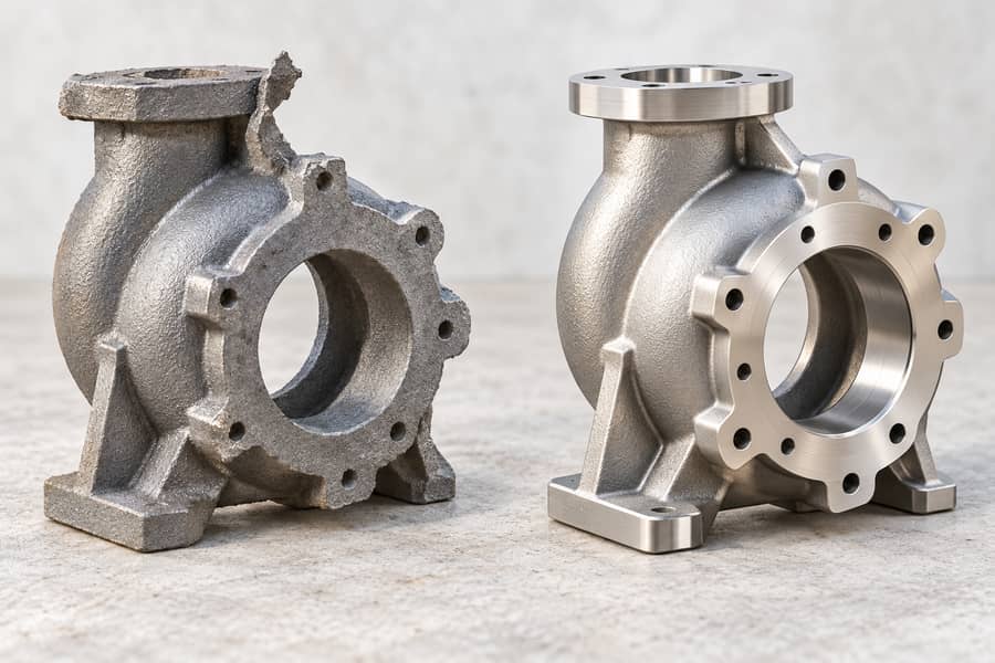
Machining allowance should be sufficient to remove the expected surface irregularities and accommodate the dimensional variation of the selected process. Too little stock may leave a critical surface incomplete, while excessive stock increases material removal, machining time, and tool wear.
Identify which surfaces require turning, milling, drilling, grinding, or other finishing operations. Establish the relationship between the raw casting and finished-part datums so that machining can consistently locate the features that control assembly and performance.
Discuss the expected casting variation before assigning allowance values. The appropriate amount depends on the process, component size, geometry, material, and required finished dimensions. A single allowance should not automatically be applied to every surface.
Manage Filling, Solidification, and Common Casting Defects
Understand Metal Filling and Solidification
During casting, molten metal must enter the mold, fill the intended cavity, and solidify in a way that produces an acceptable component. The gating system, mold conditions, metal temperature, flow paths, and section geometry all influence this sequence.
As metal cools, it contracts. Feeding systems must supply additional molten metal where necessary to compensate for solidification shrinkage. Risers, chills, and other process measures may help direct solidification, but their effectiveness depends on the casting’s geometry and material.
Designers do not normally determine every gating or feeding detail independently. Their responsibility is to provide a geometry that can be manufactured reliably and to review potential problem areas with process engineers. Changes to heavy sections, isolated masses, or narrow connections may affect the entire solidification pattern.
Identify Design-Related Casting Defects
Shrinkage porosity can occur when insufficient liquid metal reaches regions that contract during solidification. Thick intersections and isolated heavy sections deserve particular attention because they may remain hot after adjacent material has solidified.
Misruns and cold shuts can arise when metal fails to fill the mold completely or separate metal fronts do not fuse adequately. Thin walls, long flow paths, and complex passages may increase filling difficulty, although the outcome also depends on process conditions.
Gas porosity, inclusions, and hot tearing have different mechanisms. Gas porosity may relate to gas entrapment or other process conditions, inclusions can involve contamination, and hot tearing may occur when contraction is restricted during solidification. These defects cannot be attributed to geometry alone.
Coordinate Design Changes With Process Engineering
When a potential defect is identified, review the geometry and process together. A change in wall thickness may improve feeding in one region but create a new hot spot elsewhere. Similarly, increasing a section’s mass to improve strength can complicate solidification if the additional material is concentrated in an unfavorable location.
Casting simulation can help evaluate filling patterns, temperature distribution, and possible shrinkage locations. For complex or high-risk parts, simulation may be supplemented by tooling trials, sample inspection, and production data. These methods support design decisions but do not replace appropriate process control and verification.
Build Defect Prevention Into the Design Review
The design review should connect each identified risk to a practical check. The following table summarizes common issues and the corresponding areas for investigation.
| Potential defect | Possible contributing factors | Design or process review |
| Shrinkage porosity | Inadequate feeding, isolated hot spots, or unfavorable solidification | Review section transitions, feeding arrangements, and solidification behavior. |
| Gas porosity | Gas entrapment or process-related gas sources | Review filling conditions, venting, and process controls. |
| Misruns or cold shuts | Difficult flow paths, thin sections, or insufficient filling conditions | Assess section geometry, flow distance, and process suitability. |
| Hot tearing | Restricted contraction and thermal stresses | Review junction geometry, restraint, and solidification conditions. |
| Inclusions | Melt cleanliness or mold-related contamination | Review material handling, melt preparation, and process controls. |
Acceptance criteria should be established according to the component’s function and applicable requirements. Not every internal indication has the same significance, and the appropriate response depends on its size, location, type, and effect on structural integrity or service performance.
Integrate Machining, Dimensional Tolerances, and Inspection
Establish Realistic Casting Tolerances
As-cast dimensions and machined dimensions represent different stages of manufacturing. Casting tolerances account for variation associated with the process, whereas machined dimensions depend on stock availability, workholding, machining operations, and measurement conditions.
Apply tighter tolerances where dimensions directly affect fit, sealing, alignment, or load transfer. Noncritical external features may permit broader tolerances when their variation does not affect performance. This approach directs machining and inspection effort toward the features that matter most.
Before finalizing the drawing, confirm that the proposed tolerances are achievable for the selected material, casting process, component geometry, and production conditions. Project-specific requirements should be agreed upon with the supplier rather than assumed from a generic capability statement.
Design for Stable Machining and Assembly
Machining plans should provide reliable datum surfaces and practical workholding locations. Irregular raw surfaces can make positioning difficult, so the design may need suitable locating pads or additional stock on important reference faces.
Material removal can also release residual stresses or change the component’s shape. Large, thin-walled castings may require particular attention to support, machining sequence, and dimensional verification between operations. The appropriate approach depends on geometry, material condition, and the amount of material being removed.
Check that tools can reach the required surfaces and that fixtures can hold the component without obstructing critical operations. For threaded holes, bearing seats, and sealing faces, machining access and inspection requirements should be considered together during the design stage.
Specify Inspection According to Component Risk
Inspection methods should reflect the material, defect risks, acceptance criteria, and consequences of failure. Visual examination and dimensional measurement are common starting points, but they cannot detect every internal discontinuity or establish every required material property.
Depending on the application, additional methods may include:
- Radiographic testing: Used to examine internal features and certain types of discontinuities where suitable.
- Ultrasonic testing: Used to detect certain internal discontinuities, subject to material, geometry, and inspection limitations.
- Liquid penetrant testing: Used to identify surface-breaking discontinuities on suitable nonporous surfaces.
- Magnetic particle testing: Used to detect surface and near-surface discontinuities in suitable ferromagnetic materials.
- Pressure or leak testing: Applied when the component’s function and specification require verification of pressure containment or leakage performance.
These methods are not interchangeable, and no single inspection method detects every defect. The inspection plan should identify the required technique, examination areas, acceptance criteria, and documentation before production begins.
Make Critical Features Verifiable
Inspection must be practical as well as technically appropriate. Deep passages, enclosed cavities, and inaccessible surfaces may require specialized methods or design adjustments to verify their condition. A feature that cannot be inspected adequately may create unnecessary uncertainty even when the nominal drawing dimensions are correct.
Material certificates, chemical analysis, mechanical testing, heat-treatment records, and nondestructive examination reports should be specified when required by the purchase specification or application. Their scope should be agreed upon in advance, including any sampling frequency or traceability requirements.
For components involving complex geometry or demanding acceptance criteria, discuss the drawing, manufacturing route, machining plan, and inspection requirements together. BOBERRY’s investment casting information can provide a starting point for discussing process suitability, while actual material options, dimensional requirements, and quality controls must be confirmed for the specific project.