
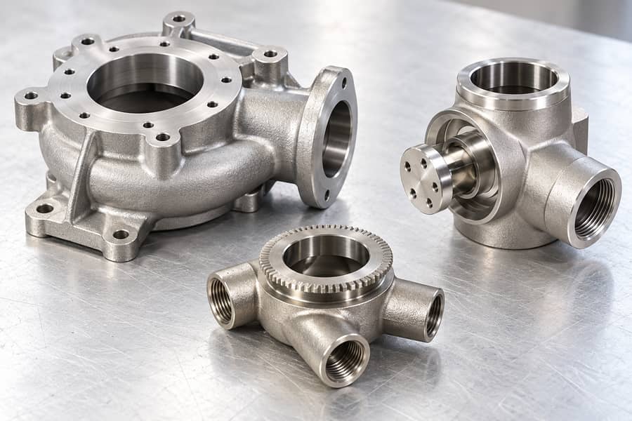
Metal casting is a manufacturing process in which molten metal fills a mold cavity, solidifies, and is removed as a component shaped by that cavity.
Engineers select a casting method by balancing alloy, geometry, production volume, dimensional requirements, internal features, and the inspection needed to verify the finished part in its intended service.
What Is Metal Casting?
Definition and Basic Manufacturing Principle
Metal casting creates a component by introducing liquid metal into a prepared mold and allowing it to solidify. The mold cavity defines the component’s basic geometry, while the selected alloy and cooling conditions influence its resulting material properties.
A casting system may contain several features beyond the cavity itself. Patterns establish the intended shape, cores form internal passages, gates direct incoming metal, and risers supply additional liquid metal to compensate for solidification shrinkage where necessary.
These elements serve different purposes and must work together. A component with a thick central section and thin external walls, for example, requires attention to filling behavior and the order in which different regions solidify.
Why Metal Casting Is Used
Casting is useful when a component has complex external contours, internal cavities, substantial cross-sections, or several integrated features. Depending on the process, it can reduce the need to assemble multiple pieces or remove large amounts of material through machining.
However, casting does not automatically produce a finished component. Mold-related surface conditions, dimensional variation, shrinkage, porosity, and other discontinuities may require additional process controls, inspection, or corrective action.
The appropriate method depends on the component’s function rather than geometry alone. A housing that supports rotating equipment, for instance, may need accurately machined bearing seats even when most of its external surfaces can remain as-cast.
Typical Applications of Cast Metal Components
Cast components appear in industrial machinery, pumps, valves, pipe fittings, equipment housings, structural assemblies, and fluid-handling systems. Their design requirements vary considerably according to mechanical loads, operating temperatures, corrosion exposure, and pressure conditions.
Engineers should therefore distinguish between the shape that casting can produce and the performance the finished component must deliver. The manufacturing route must satisfy both requirements without assuming that an acceptable external appearance proves internal integrity.
How Does Metal Casting Work Step by Step?
Step 1: Component Design and Pattern Preparation
The process begins with a component drawing that defines geometry, material requirements, functional surfaces, and acceptance criteria. The casting design is then reviewed to identify features that may complicate mold filling, solidification, removal, or subsequent machining.
A pattern represents the intended casting geometry and includes appropriate allowances for the chosen process. These may account for metal contraction during cooling, material removed during machining, and draft angles needed to withdraw a pattern from an expendable mold.
Designers also establish parting lines and determine whether cores are necessary. Poorly located parting lines can create finishing difficulties, while complicated cores may increase tooling requirements and introduce additional risks related to positioning or breakage.
Step 2: Mold and Core Preparation
The mold provides the cavity into which the metal flows. Depending on the casting method, it may be made from prepared sand, ceramic shell materials, or reusable metal tooling. These materials differ in thermal behavior, strength, permeability, surface characteristics, and suitability for particular alloys and pouring conditions.
Cores are placed inside the mold when internal passages or cavities cannot be formed by the external mold surfaces alone. Their dimensions and positioning must account for the intended wall thickness and the forces generated during filling.
Mold preparation also includes establishing the gating system and any required risers or vents. Gating influences how metal enters and travels through the cavity, while vents help gases escape. The layout should reduce turbulence and avoid trapping air or allowing premature solidification to interrupt filling.
Step 3: Metal Melting and Pouring
The specified alloy is melted under controlled conditions, with attention to chemical composition, temperature, and contamination. The molten metal must remain suitable for filling the cavity without introducing unacceptable inclusions or other defects.
Pouring temperature requires a balance. Metal that loses heat too quickly may solidify before filling thin or distant sections, while excessive temperature can increase mold reactions, oxidation, or other process-related risks. Appropriate values depend on the alloy, component geometry, mold material, and casting method.
Gravity casting relies primarily on gravity to move metal into the mold. Die casting instead uses pressure to force molten metal into a reusable metal die. The filling mechanism affects tooling design, achievable geometry, process controls, and the types of defects that require attention.
Step 4: Solidification and Cooling
After filling, the molten metal transfers heat into the surrounding mold and gradually solidifies. Different regions may cool at different rates because of changes in wall thickness, local geometry, mold characteristics, and the availability of heat-flow paths.
As metal contracts during solidification, some regions may require additional liquid metal from a riser. If feeding is inadequate, shrinkage cavities or distributed shrinkage porosity can develop. Directional solidification helps designers plan how solidification progresses toward regions where shrinkage can be compensated.
Cooling continues until the casting can be safely removed and handled. Depending on the alloy and geometry, uneven cooling may also create residual stresses or distortion. The cooling schedule must therefore suit the component rather than simply minimize the time spent in the mold.
Step 5: Casting Removal and Finishing
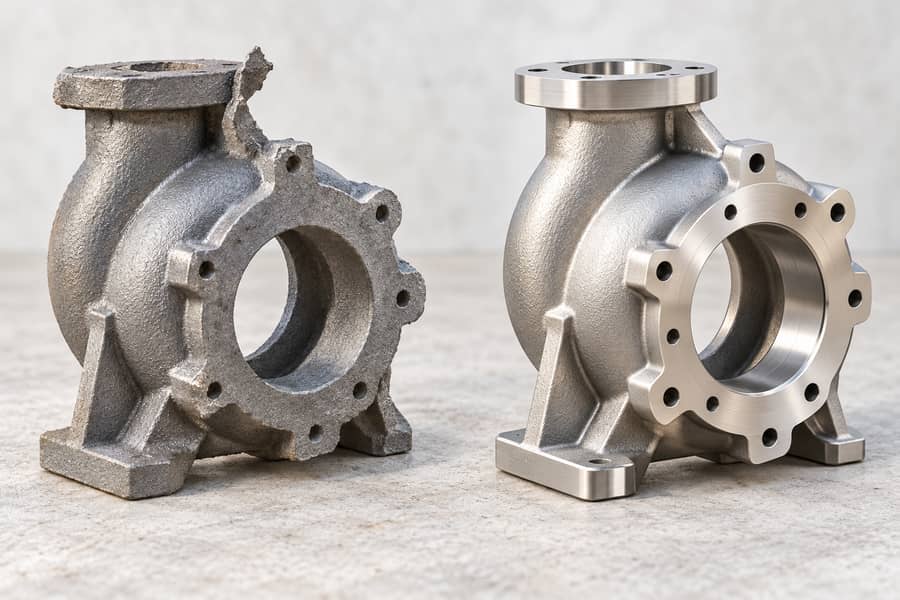
Once the casting has solidified sufficiently, it is removed from the mold. Expendable molds are broken or otherwise discarded, while reusable molds are opened to release the component. Cores are removed as required, and gates, risers, flash, and excess material are separated from the casting.
Subsequent operations may include surface cleaning, grinding, heat treatment, straightening, or machining. Not every casting needs every operation. Heat treatment depends on the alloy and required properties, while machining is generally concentrated on features that need specified dimensions, surface finishes, or geometric relationships.
Step 6: Inspection and Release
The finished component is inspected against its drawing and purchase specification. Typical checks include dimensional measurement, visual examination, material verification, and assessment of specified mechanical properties. Nondestructive testing may be required when internal integrity or surface discontinuities are important to component performance.
Acceptance criteria should identify the relevant inspection method, test location, sampling frequency, and permissible indications. A casting is suitable for release only when the required checks have been completed and the results satisfy the applicable requirements.
What Are the Main Types of Metal Casting?
Sand Casting
Sand casting uses a mold formed from prepared sand or a related molding material. The mold is generally expendable, making the process adaptable to a wide range of component geometries and sizes. Cores can create internal passages and cavities that would otherwise require extensive machining or assembly.
Tooling can be relatively flexible compared with permanent metal dies, which may make sand casting attractive for large components or production programs with changing designs. However, surface finish and dimensional control depend on the molding system, pattern quality, alloy, and process conditions. Machining allowances may be necessary on critical surfaces.
Investment Casting
Investment casting commonly uses a disposable pattern surrounded by a ceramic shell. After the pattern is removed, molten metal is introduced into the resulting cavity. The method can produce intricate geometries and detailed features that would be difficult to manufacture economically through conventional machining alone.
Its suitability depends on component dimensions, alloy, shell behavior, production requirements, and acceptance criteria. Shell preparation, pattern quality, and solidification control remain important to the final result. For additional process context, see BOBERRY’s investment casting information.
Die Casting
Die casting forces molten metal into a reusable metal die under pressure. It is commonly associated with nonferrous alloys that are compatible with the selected equipment and die materials. Hot-chamber and cold-chamber processes differ in how the molten metal is supplied and injected.
Reusable tooling can support repeatable production, while rapid filling may allow relatively thin walls and detailed features. These advantages must be weighed against tooling investment, die design constraints, alloy compatibility, and the need to control gas entrapment, porosity, and other process-related defects.
Permanent Mold and Other Casting Methods
Permanent-mold casting uses reusable molds, often filled by gravity. It can offer useful repeatability and surface characteristics for suitable alloys and geometries. Centrifugal casting uses rotation to distribute molten metal within a mold and is particularly relevant to certain hollow or rotationally symmetrical components.
Neither method is suitable for every alloy or component. Mold temperature, thermal loading, geometry, production volume, and required material properties must be evaluated before selecting a process.
The following table summarizes general manufacturing trade-offs. Actual results depend on the specific equipment, tooling, alloy, component design, and process controls.
| Casting method | Typical advantages | Main limitations | Key selection considerations |
| Sand casting | Flexible tooling and broad geometric adaptability | Surface finish and dimensional control may require additional work | Component size, cores, machining stock, and production volume |
| Investment casting | Intricate geometry and detailed features | Shell preparation and pattern production add process steps | Feature complexity, alloy, dimensions, and inspection requirements |
| Die casting | Reusable tooling and repeatable high-volume production | Tooling investment and alloy compatibility constraints | Production quantity, wall thickness, pressure filling, and defect control |
| Permanent-mold casting | Reusable tooling and potential for consistent results | Geometry, mold temperature, and alloy choices may be restricted | Part shape, thermal conditions, and expected production volume |
| Centrifugal casting | Useful for suitable hollow or rotationally symmetrical components | Limited suitability for many irregular geometries | Rotational geometry, material distribution, and required properties |
Which Metals and Alloys Can Be Used for Casting?
Cast Iron and Cast Steel
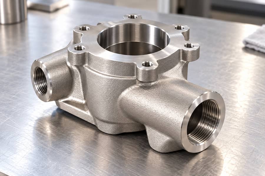
Cast iron and cast steel are ferrous materials, but their compositions, microstructures, and resulting properties differ. Cast iron generally contains more carbon than steel, and its behavior depends on the specific iron grade, graphite structure, matrix, and processing conditions.
Cast steel can be appropriate when the component requires a particular combination of strength, toughness, weldability, or service performance. Its suitability depends on the grade, section thickness, heat treatment, and verified mechanical properties rather than the word steel alone.
For both material families, buyers should specify the applicable casting standard and grade. Requirements for chemical composition, mechanical testing, heat treatment, and inspection should be defined according to the component’s intended service and governing specification.
Aluminum and Other Nonferrous Casting Alloys
Aluminum casting alloys are often considered when low density, corrosion behavior, or thermal conductivity is important. Their mechanical properties, castability, heat-treatment response, and corrosion resistance vary by alloy and manufacturing process.
Copper-based alloys may be selected for particular combinations of corrosion resistance, conductivity, wear behavior, or service conditions. Other nonferrous alloys can address specialized requirements, but their melting characteristics and compatibility with the selected mold or die must be considered.
Material selection should begin with the operating environment and required performance. Density alone is not enough to justify replacing one alloy with another, particularly when the component must withstand pressure, cyclic loads, elevated temperatures, or corrosive media.
How to Interpret Casting Material Specifications
Cast and wrought material specifications are not automatically interchangeable, even when their alloy designations appear similar. Casting introduces a different solidification history and potentially different microstructures, so the applicable material standard must match the manufacturing form.
For example, CF8 and CF8M are cast stainless steel grades, whereas 304 and 316 are commonly used for wrought stainless steel products. Although these materials may have related chemical compositions, their specifications, processing histories, and mechanical property requirements differ. Engineers must verify the applicable cast grade rather than assume that a wrought grade provides an equivalent specification.
For stainless steel castings, the material standard should define the required grade, chemical composition, heat treatment, and mechanical testing. CF8M, for example, should be specified according to its applicable casting standard rather than treated as an automatic substitute for wrought 316 stainless steel.
Buyers should also confirm the required corrosion resistance for the actual service environment. Chloride concentration, temperature, cleaning chemicals, and exposure duration can affect material suitability, so grade selection should reflect operating conditions rather than a general stainless steel designation.
How Does Casting Design Affect Component Quality?
Wall Thickness, Transitions, and Solidification
Component geometry influences how molten metal fills a mold and how heat leaves the casting. Thick sections generally retain heat longer than thin sections, potentially creating isolated regions that solidify later and become vulnerable to shrinkage defects.
Designers should review abrupt thickness changes, heavy intersections, and isolated masses before finalizing the casting geometry. Gradual transitions and appropriate fillets can improve material flow and reduce local stress concentrations, although the correct geometry depends on loading and manufacturing constraints.
Reducing wall thickness may lower component mass, but excessively thin sections can make complete filling more difficult. The design must balance structural requirements, casting feasibility, and the consequences of adding material or machining features later.
Draft Angles, Cores, and Parting Lines
Draft angles help patterns or components release from their molds where the selected process requires them. The necessary draft depends on mold material, surface texture, geometry, and the direction of removal. Reusable metal dies introduce their own release and ejection requirements.
Core placement determines whether internal passages have the required dimensions and wall thickness. Engineers should examine core support, positioning, accessibility, and the possibility of movement during filling. Poorly controlled core placement can create uneven walls or interfere with subsequent machining.
Parting-line location also affects finishing. Placing a parting line across a critical sealing surface may increase cleanup requirements or complicate dimensional control. The design review should identify these interfaces early, especially when the casting will later be machined into a precision assembly component.
Machining Allowances and Functional Features
As-cast surfaces do not necessarily meet the dimensional tolerances or surface finish required for assembly. Bearing seats, sealing faces, precision bores, and threaded interfaces may require machining to establish their final dimensions and geometric relationships.
Drawings should identify machining stock, critical dimensions, datums, and surface-finish requirements. Excessive machining allowance increases material removal, while insufficient allowance can leave a surface below its required dimension when casting variation occurs.
Near-net-shape design aims to minimize unnecessary machining without compromising functional requirements. Whether this is practical depends on the casting process, geometry, alloy, and demonstrated process capability. Tolerances should be confirmed for the specific component rather than assumed from the casting method’s general description.
What Are Common Casting Defects and How Are They Controlled?
Porosity, Shrinkage, and Inclusions
Porosity refers to cavities within or at the surface of a casting. Gas porosity can arise from trapped gas or gas released during processing, while shrinkage porosity develops when solidification contraction is not adequately compensated. Inclusions are unwanted nonmetallic or foreign materials trapped in the metal.
Control measures depend on the defect mechanism. Melt cleanliness, suitable venting, controlled filling, and appropriate gating can help reduce certain defects. Feeding design and solidification analysis help address shrinkage, but no single adjustment eliminates every possible source of porosity.
Misruns, Cold Shuts, Cracks, and Distortion
A misrun occurs when metal fails to fill part of the mold. A cold shut forms when separate metal streams meet without adequately joining. Both may be associated with insufficient fluidity, premature cooling, or unsuitable filling conditions.
Cracks can develop from thermal stresses, contraction restraint, or material and process conditions. Distortion occurs when uneven cooling or residual stresses change the component’s shape. Corrective measures may include revising the geometry, adjusting pouring conditions, improving mold design, or modifying cooling and heat-treatment procedures where appropriate.
Inspection Methods and Acceptance Criteria
Inspection must reflect the component’s intended function and the defects that could compromise it. Visual examination and dimensional measurement address surface condition and geometry, while other methods can assess specified material or internal-integrity requirements.
- Visual inspection: Identify visible cracks, surface discontinuities, incomplete filling, and finishing problems.
- Dimensional inspection: Verify critical dimensions, datum relationships, and machining requirements against the drawing.
- Radiographic testing: Examine suitable castings for certain internal discontinuities, subject to material, geometry, and technique limitations.
- Ultrasonic testing: Assess suitable materials and geometries for internal indications when the method is appropriate.
- Penetrant or magnetic-particle testing: Detect relevant surface or near-surface discontinuities, depending on material and test method.
Testing requirements should state the inspection method, extent, acceptance criteria, and reporting requirements. The presence of an indication does not automatically establish rejection; its significance depends on the applicable specification and component function.
| Defect | Possible cause | Potential impact | Relevant control or inspection |
| Gas porosity | Gas entrapment or inadequate venting | Reduced integrity or leakage risk in critical applications | Melt and filling control; specified radiographic examination where appropriate |
| Shrinkage cavity | Inadequate feeding during solidification | Local loss of section or structural integrity | Riser design, solidification control, and appropriate internal inspection |
| Inclusions | Oxides, slag, or other foreign material entering the casting | Potential reduction in mechanical performance | Melt cleanliness, gating control, and specified examination |
| Misrun or cold shut | Incomplete filling or insufficient fusion between metal streams | Incomplete geometry or a discontinuity in the component | Filling analysis, process adjustment, and visual inspection |
| Cracking | Thermal stress, contraction restraint, or unsuitable processing | Loss of structural integrity | Design and process review; suitable crack-detection methods |
| Distortion | Uneven cooling or residual stress | Dimensional deviation or assembly difficulties | Cooling control, dimensional inspection, and approved corrective processing |
How Should Engineers and Buyers Specify a Cast Metal Component?
Define Functional and Material Requirements
A useful casting specification begins with the operating requirements. Engineers should document loads, temperature ranges, pressure exposure, corrosion conditions, expected service life, and any consequences of component failure. These factors help determine the appropriate material, geometry, and inspection scope.
The drawing should identify critical dimensions, tolerances, datums, surface finishes, and machining requirements. It should also specify the applicable casting material standard and grade, along with any required heat treatment, mechanical properties, chemical analysis, or nondestructive testing.
Evaluate Process Suitability and Total Manufacturing Requirements
Process selection should consider more than the initial casting operation. Tooling, production quantity, material yield, machining, finishing, inspection, and the risk of rejected parts all influence the overall manufacturing decision.
For example, a complex component produced in substantial quantities may justify reusable tooling if the geometry and alloy are suitable. A large component with changing design requirements may instead favor an expendable mold process. These are conditional choices, not universal rules.
When evaluating a proposed casting route, ask the supplier to explain how the process accommodates critical features, internal cavities, required tolerances, and inspection needs. Confirm whether the quoted scope includes machining, heat treatment, surface finishing, testing, and material documentation.
Confirm Supplier Scope and Quality Documentation
BOBERRY supplies forged and cast mechanical parts, with project requirements determining the appropriate manufacturing route and agreed scope. Its casting information provides a starting point for discussing cast components and their application requirements.
Before placing an order, engineers and sourcing professionals should confirm the proposed casting method, applicable material specification, production requirements, inspection plan, and acceptance criteria. Any required certificates, traceability records, or test reports should be agreed upon explicitly.
Supplier capabilities, achievable tolerances, and available inspection methods must be verified for the specific project. Clear drawings and documented acceptance requirements help align component design, manufacturing controls, and final verification before production begins.