
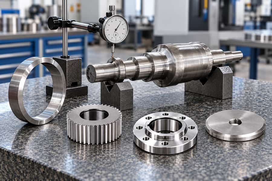
Forging quality control verifies that forged components meet specified material, dimensional, surface, and internal integrity requirements. It combines process monitoring with inspections that identify defects before parts enter service.
Effective plans consider alloy, geometry, forging method, service loads, and machining requirements. Engineers and buyers also need clear acceptance criteria, reliable test records, and material traceability.
What Forging Quality Control Must Verify
A forging can have the correct external shape yet contain an internal discontinuity, unsuitable microstructure, or incorrect material. No single inspection method establishes all aspects of product quality.
Quality control therefore combines preventive process checks with product verification. Process records indicate whether manufacturing conditions were controlled; examination and testing determine whether selected characteristics meet their requirements.
- Material identity: Confirm the specified alloy and preserve identification from incoming stock through finished parts.
- Dimensional conformity: Check critical geometry, machining allowances, and finished features against the drawing.
- Surface and internal integrity: Examine relevant areas for discontinuities using methods suited to the material and likely defect locations.
- Mechanical properties: Verify required strength, hardness, ductility, or toughness using appropriate tests and representative specimens.
Inspection intensity should reflect the consequences of failure. A heavily loaded shaft shoulder may warrant tighter verification than a nonfunctional surface, even when both appear on the same drawing.
Planning Inspections Throughout Forging Production
Define Requirements Before Manufacturing
The inspection plan begins with the drawing, material specification, intended service, and purchasing requirements. Engineers should identify critical-to-function features rather than treat every dimension as equally important.
A practical plan specifies the inspection method, measurement stage, coverage, frequency, acceptance criteria, and responsible reviewer. It should also identify any hold points requiring approval before processing continues.
Check Incoming Material and Traceability
Incoming bars, billets, or ingots require identification checks and examination for relevant surface damage. Material certificates can establish reported chemistry and test results, but documentation must correspond to the actual stock received.
Chemical analysis may be necessary when composition needs independent verification. Portable alloy identification is useful for certain elements, but the selected technique may not adequately quantify carbon or other critical constituents.
Heat numbers or other traceable identifiers must survive cutting and transfer operations through a controlled marking or record system. Mixing similar-looking alloys can undermine every inspection performed later.
Monitor Forming Conditions and Tooling
Heating and deformation conditions affect metal flow, grain development, and defect formation. Inappropriate temperatures may contribute to cracking, excessive grain growth, or poor filling, depending on the alloy and operation.
For die forging, check tooling condition, alignment, flash behavior, and the first acceptable production pieces. Worn cavities or poor positioning can produce repeatable dimensional errors across an entire batch.
For free-form deformation, operators must monitor shape development, reduction sequence, and intermediate dimensions. Recorded process parameters support investigation, but acceptable readings do not replace examination of the resulting forging.
Verify Heat Treatment and Subsequent Operations
Heat treatment records should document relevant furnace conditions, holding periods, and cooling operations. The required review depends on the specified material condition and whether the treatment governs final mechanical properties.
Hardness checks can reveal inconsistent results, but hardness alone does not prove the required toughness or microstructure. Straightening, cleaning, and machining may introduce new risks that require additional checks.
Final inspection should occur at a stage when required surfaces are accessible and dimensions represent the ordered condition. Inspection before and after machining may serve different purposes rather than duplicate work.
Visual and Dimensional Inspection Methods
Visual Examination of Forged Surfaces
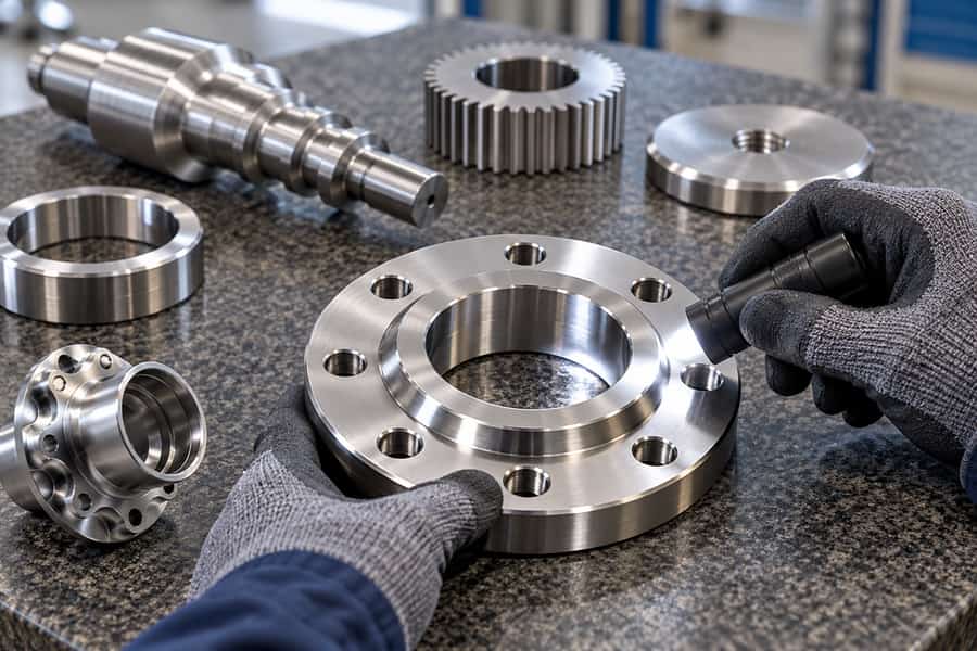
Visual inspection is a useful first screen for underfill, laps, surface cracks, scale-related damage, and unusual deformation. Adequate lighting, cleanliness, and access are essential to interpreting what is visible.
Inspectors should distinguish ordinary forging texture or permissible flash remnants from suspect indications. When a line or surface feature cannot be classified visually, further examination may be necessary.
Surface condition matters: heavy scale, coatings, or rough profiles may obscure fine discontinuities. Visual acceptance therefore depends on the agreed condition of the part at inspection.
Dimensional Measurement and Drawing Interpretation
Calipers, micrometers, bore gauges, templates, and coordinate measuring machines serve different measurement tasks. Tool selection depends on feature size, access, tolerance, and the uncertainty of the measurement process.
Inspect functional diameters, lengths, thicknesses, and relevant geometric relationships such as runout or concentricity. Datum selection must follow the drawing, especially when later machining establishes the final reference surfaces.
As-forged dimensions often differ from finished machining dimensions because stock is intentionally left for cleanup. A forging can meet its intermediate dimensions while a finished feature still requires separate verification.
When to Measure and How Much to Inspect
First-piece checks can reveal setup problems before repeated production. Periodic checks help identify drift, while final measurements confirm the condition of parts presented for acceptance.
Critical features may call for complete inspection, whereas other characteristics can follow an agreed sampling plan. The decision should account for process stability, lot size, inspection uncertainty, and failure consequence.
Nondestructive Testing Methods for Forged Components
Nondestructive testing evaluates selected discontinuities without cutting apart the finished component. Each method has detection limits, and an indicated flaw does not automatically mean the forging fails its acceptance criteria.
Checking Ferromagnetic Surfaces with Magnetic Particles
In a magnetized ferromagnetic part, discontinuities can create local flux leakage. Fine particles gather at these locations, forming visible indications at the surface or, in suitable cases, just beneath it. Crack orientation relative to the field affects detection.
Testing may require more than one magnetization direction. Material condition, surface preparation, and complex geometry influence results; nonferromagnetic alloys cannot be examined by this method.
Liquid Penetrant Testing
Liquid penetrant testing applies a penetrant to a clean, nonporous surface, removes the excess, and uses developer to make surface-breaking openings visible. It is not limited to ferromagnetic materials.
Open cracks and laps may produce relevant indications, but enclosed internal defects will not. Rough surfaces, contamination, and incomplete cleaning can complicate interpretation or create misleading indications.
Ultrasonic Testing
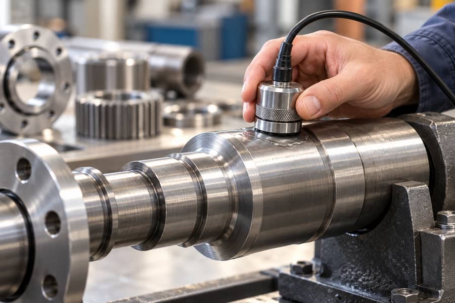
Ultrasonic testing sends sound into the forging and evaluates returned signals or transmitted energy for evidence of internal discontinuities. It is often considered when volumetric integrity is important.
Inspectability depends on section thickness, curvature, surface condition, grain structure, and access for probe movement. Coarse or complex microstructures can scatter sound and reduce useful sensitivity.
A written procedure should define scanning coverage, calibration references, evaluation thresholds, and reporting. A region that cannot be scanned adequately must not be described as fully inspected.
Radiographic Testing
Radiographic testing uses transmitted radiation to record variations associated with thickness or material density. It may reveal certain internal defects when geometry and technique permit adequate contrast.
Dense, thick sections can make radiography less practical, and planar defects may be difficult to reveal in unfavorable orientations. Access, radiation controls, and image interpretation also influence selection.
| Method | Primary Inspection Target | Suitable Conditions | Main Limitation |
| Magnetic particle (MT) | Surface and near-surface discontinuities | Ferromagnetic forgings | Not applicable to nonferromagnetic metals |
| Liquid penetrant (PT) | Surface-breaking discontinuities | Clean, nonporous accessible surfaces | Cannot reveal enclosed internal flaws |
| Ultrasonic (UT) | Selected internal discontinuities | Sections with suitable acoustic access | Geometry and grain structure affect detection |
| Radiographic (RT) | Internal density or thickness variations | Sections allowing useful transmission and positioning | Thickness and defect orientation constrain sensitivity |
These methods are not interchangeable. Selecting more tests does not necessarily improve assurance unless each method addresses a defined risk and uses appropriate coverage and acceptance rules.
Mechanical Testing and Metallurgical Examination
Hardness and Heat Treatment Verification
Hardness testing is commonly used to assess whether a forging is consistent with its specified heat-treated condition. Test locations and surface preparation matter because decarburization or local variation can distort readings.
Hardness results can support process control and screening, but they cannot establish tensile strength, impact toughness, or fatigue performance by themselves. Any conversion between property scales requires caution and authorization.
Verifying Tensile Behavior and Notched Impact Response
Pulling a prepared specimen under controlled conditions establishes its yield behavior, maximum tensile stress, and extension before fracture. Results represent the tested material and location, not automatically every region of a large forging.
Impact testing assesses energy absorbed by a notched specimen under specified conditions. It is especially relevant when service temperature and resistance to brittle fracture are design considerations.
Specimen orientation, extraction location, heat treatment, and test temperature must match the applicable specification. A sample taken from convenient excess material is not automatically representative of the most heavily worked section.
Microstructure, Grain Flow, and Internal Material Condition
Microscopic examination can evaluate phase distribution, grain size, inclusions, and potentially harmful structural conditions. Sample preparation and the chosen examination location determine what the metallographer can observe.
Macroetching or section examination can help reveal flow patterns and larger-scale structural features when specified. Grain flow may inform assessment of the forging route, but favorable patterns do not replace strength testing.
Destructive tests usually consume specimens or sacrificial material, so sampling needs advance agreement. Engineers must identify which production lot, heat, and processing condition each result represents.
Common Forging Defects and Their Inspection Routes
Defects have different origins and inspection signatures. A lap may form where metal folds over itself, while an internal burst may develop from unfavorable deformation and stress conditions.
Incomplete fill primarily affects geometry, whereas undesirable microstructure concerns material condition. Matching the suspected defect to its likely location helps prevent reliance on an unsuitable inspection method.
| Potential Defect | Engineering Concern | Useful Inspection Approach |
| Surface crack | Possible initiation site for service failure | Visual examination, MT or PT as applicable |
| Lap or fold | Unbonded or weak surface region | Visual examination and suitable surface NDT |
| Underfill | Missing required geometry or machining stock | Visual and dimensional checks |
| Internal burst | Loss of internal soundness | Qualified UT or another appropriate volumetric method |
| Nonmetallic inclusion | Possible local weakness or discontinuity | Metallography and applicable volumetric inspection |
| Undesirable microstructure | Mismatch with required material behavior | Metallography and relevant property tests |
| Heat treatment distortion | Loss of geometric conformity | Dimensional and geometric inspection |
Detection is only the first step. Inspectors must evaluate indication size, position, orientation, and the specified acceptance rules before deciding whether repair, further examination, or rejection is appropriate.
For a hypothetical example, a surface indication at a shaft fillet deserves different engineering attention from a similar indication on a removable machining allowance. The applicable specification still governs disposition.
Acceptance Criteria, Sampling, and Nonconforming Parts
Establish Criteria Before Inspecting
Acceptance criteria should identify permitted dimensions, property ranges, and relevant NDT indication limits. A requirement to perform ultrasonic testing is incomplete without coverage, procedure, and evaluation instructions.
Engineering drawings and purchase requirements may control different features. If requirements conflict or an area is unspecified, obtain clarification before treating an inspection result as acceptable.
Choose Inspection Coverage Based on Risk
Complete inspection can be appropriate for accessible critical characteristics, but it does not eliminate measurement error or guarantee detection of every defect. Sampling reduces effort while introducing a risk of missed nonconformance.
Sampling plans should define lot boundaries and selection rules, not just a convenient number of pieces. A change in material heat, forging setup, or treatment cycle may warrant a distinct evaluation group.
Control Nonconformance and Reinspection
Suspect parts should be identified and separated from conforming material until disposition is authorized. The investigation should consider whether the same condition might affect other parts from the batch.
Possible actions include additional inspection, approved rework, engineering concession, or rejection. Repaired or reworked components need verification against the requirements affected by that operation.
Repeated defects warrant review of root causes such as tooling wear, material condition, temperature control, or handling. Corrective actions should be checked for effectiveness rather than judged solely by completed paperwork.
Inspection Priorities for Different Forging Routes and Geometries
Open-Die and Closed-Die Forging
In open-die forging, broad deformation sequences and large sections can make stock allowance, straightness, internal soundness, and representative testing locations important planning considerations.
Closed-die forgings often require careful monitoring of die fill, parting-line features, flash removal, and cavity wear. Complex contours can also restrict probe access for nondestructive examination.
Neither route is inherently free of defects. Inspection should reflect the actual process, reduction history, geometry, alloy, and intended use rather than rely on a generic checklist.
Component-Specific Critical Features
Shafts may require attention to bearing seats, shoulders, runout, and fatigue-sensitive transitions. Flanges and rings may prioritize bore geometry, face condition, section uniformity, and specified internal examination zones.
Hubs and gears introduce additional concerns about machined interfaces, concentricity, and material condition near heavily loaded features. Final inspection must match the delivered manufacturing stage and drawing requirements.
Inspection Documentation and Supplier Communication
Build a Traceable Inspection Record
Useful records link each inspected part or lot to its material identity, process history, inspection results, and acceptance decision. The necessary detail depends on contractual and application requirements.
A dimensional report should identify measured features and actual readings, not only state that a part passed. NDT reports should specify method, examined areas, procedure, results, and interpretation.
When relevant, request test specimen identification, heat treatment records, equipment calibration status, and inspector qualifications. Retention requirements should be agreed early so important evidence remains available after shipment.
Resolve Inspection Scope Before Purchase Approval
Buyers should distinguish mandatory evidence from optional verification. Requiring every available test can create unnecessary cost or delay without addressing the component’s dominant failure risks.
The quotation and order should state who arranges special testing, who reviews results, and what happens when an indication requires engineering disposition. Unclear responsibilities frequently create disputes late in production.
Specifying Quality Requirements for BOBERRY Forgings
BOBERRY offers custom forged shafts, flanges, hubs, rings, and gears, with open-die and closed-die routes and post-machining options. Its forging solutions provide a starting point for discussing part geometry and manufacturing approach.
Those product and process categories do not establish which inspection equipment, procedures, certifications, or test arrangements are available for a particular order. Such details should be confirmed directly during technical review.
A useful request for quotation gives the supplier sufficient information to plan both manufacturing and acceptance, rather than adding inspection requirements after material has already been processed.
- Part definition: Provide controlled drawings, revision levels, quantities, and the required delivery condition.
- Material and service: Identify alloy grade, applicable specification, heat treatment condition, loading, and operating temperature where relevant.
- Critical features: Highlight functional dimensions, datums, machining allowances, and surfaces exposed to severe service stresses.
- Inspection scope: Specify required visual, dimensional, surface, volumetric, and property examinations with coverage and frequency.
- Acceptance rules: State the governing criteria, reporting thresholds, and authority for nonconformance disposition.
- Delivery records: Define traceability, material certificates, test reports, and any required independent review before release.
Where a method is uncertain, ask for a feasibility review based on the actual section thickness, surface accessibility, material structure, and drawing features. A technically achievable inspection plan is more valuable than an undefined promise of comprehensive testing.
Agreeing on those details before production gives engineers evidence matched to design risk and gives sourcing teams a clear basis for comparing quotations, approving documentation, and accepting finished forgings.