
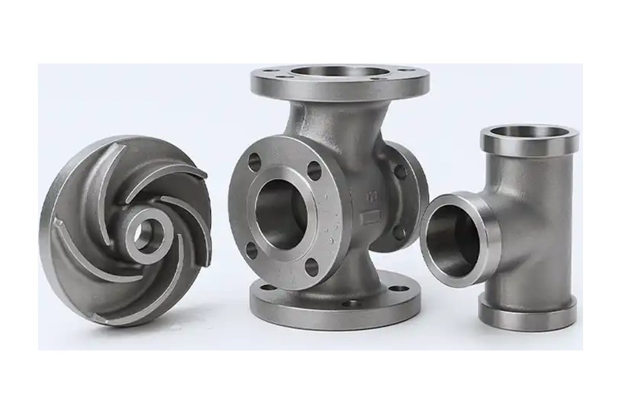
Machining duplex stainless steel parts requires a process that controls cutting forces, component movement, and the condition of the finished surfaces together. Tool wear can change a dimension before an insert visibly fails, while a thin casting can spring away from its inspected shape after the fixture is released. A successful machining route therefore depends on more than selecting a cutting speed.
For buyers of pump components, valve bodies, flanges, and other industrial parts, the important question is whether the supplier has connected material verification, machining sequence, and inspection to the drawing. The following process review follows a component from incoming material to final release and identifies the decisions that most directly affect acceptance.
Before cutting: verify the material and delivery condition
Duplex stainless steel contains both ferritic and austenitic phases. Different grades within this family are selected for different combinations of properties and service requirements. The general name does not identify one universal machining response, heat-treatment condition, or corrosion capability.
Start with the specified grade, product form, and material standard. A casting and a wrought product should not be assumed interchangeable merely because their common commercial descriptions sound similar. Confirm the applicable designation and delivery requirements before planning machining around an assumed material condition.
For duplex stainless steel castings, review the supplied geometry and the location of machining stock. Uneven stock can change how forces develop during the first operations. Parting features, transitions, internal passages, and local wall thickness also influence how the component can be supported without distortion.
Check the records that influence the process
Material identification and heat-treatment records should be traceable to the component or lot. Where hardness, microstructure, or supplementary testing is required, define the acceptance criteria and sampling basis in the purchase specification. A material certificate should be read against those requirements rather than treated as a generic assurance that every relevant condition has been verified.
Positive material identification can help verify chemistry within the capability of the selected method. It does not independently demonstrate the complete heat-treatment history, phase condition, or mechanical properties. Likewise, a hardness reading cannot replace every other material acceptance requirement.
Review any repair history that affects the delivered part. If welding or another repair operation is permitted, the applicable procedure, inspection, and documentation belong in the manufacturing record. The machine shop needs to know about conditions that may influence the material or geometry before it treats the blank as uniform.
Roughing: release stock without losing the geometry
Rough machining changes the balance of material and can expose movement that was not obvious in the incoming blank. Residual stress, uneven stock removal, part stiffness, and fixture forces can all contribute. When a dimension moves after roughing, identify the mechanism before prescribing a generic stress-relief operation.
A staged route may leave material for later finishing while the part is checked after major stock removal. On an asymmetric housing, the order of opening bores, facing mounting surfaces, and reducing wall sections can affect the stiffness available for subsequent cuts. The best sequence depends on the actual geometry and the features that must remain related.
Separate elastic fixture distortion from permanent movement
Clamping can hold a flexible component in a shape that it does not retain when released. A bore machined round while the surrounding body is distorted may change form afterward. More clamping force is therefore not automatically better. The fixture needs enough restraint to resist cutting loads without unnecessarily changing the part.
Support the component near appropriate load paths and avoid concentrating force on weak walls or unsupported projections. The machining team should understand which surfaces are stable references at each stage. A rough exterior that is convenient for initial location may not remain the best reference after critical surfaces are established.
Compare selected measurements while clamped and after release when distortion is a concern. Record the setup and the part condition with those values. Otherwise, two measurements can appear inconsistent even though they describe different physical states of the same component.
Do not apply a familiar carbon-steel thermal treatment to duplex stainless steel without a grade-specific, approved basis. Thermal exposure can affect the material condition and intended properties. Any proposed heat-treatment change needs to be reviewed against the material specification and the complete manufacturing route.
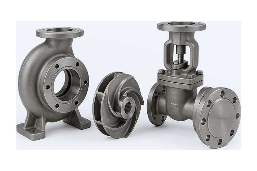
At the cutting edge: diagnose wear before adjusting parameters
The machining plan must accommodate the strength and work-hardening behavior of the actual grade. An edge that rubs instead of cutting cleanly can leave a surface that is harder to machine on the following pass. The aim is consistent material removal with a tool and setup suited to the operation, rather than repeated light passes that fail to cut cleanly.
Choose the tool geometry, edge preparation, and cutting parameters for the grade, operation, and machine rigidity. A deep interrupted roughing cut and a stable finishing pass need different considerations. Universal speed and feed numbers are not useful when the tool, diameter, engagement, and support conditions are unspecified.
Read the wear pattern as process evidence
Progressive flank wear can create gradual dimensional drift. Chipping may produce sudden changes in finish or size. Material adhering to the edge can alter the effective cutting geometry. Notch wear can concentrate at a repeated engagement boundary. These observations should be recorded with the cutting conditions and the portion of the part being machined.
A photograph of the used edge is often more useful than a note saying “poor tool life.” Include the number of parts or cutting time, the operation, and whether the tool was changed for wear, breakage, or dimensional control. That makes later trials comparable and helps avoid changing several variables without understanding the result.
| Observed condition | Questions to investigate | Evidence to retain |
| Gradual diameter drift | Is edge wear or thermal change affecting the cut? | Measurement trend and tool condition |
| Intermittent chipping | Are interruption, vibration, or edge loading involved? | Damaged edge and operation details |
| Torn or smeared surface | Is material adhesion or an ineffective cut occurring? | Surface photographs and cutting settings |
| Repeated marks in a bore | Are chips being trapped or recut? | Chip form, coolant delivery, and bore location |
Keep chip control and coolant delivery consistent
Chips that remain in a pocket or bore can damage the surface and interfere with the next cut. The strategy needs to provide a reliable path for evacuation. This is particularly relevant in internal passages where the cutting zone is difficult to observe directly and the tool has limited stiffness.
Coolant selection and delivery should match the tool and operation. Record the approved conditions and monitor whether fluid actually reaches the working zone. A nozzle aimed at the general work area may not provide consistent delivery inside a deep feature. Changes in flow, concentration, or chip obstruction can alter an otherwise stable process.
Choose the acceptance measures before comparing the revised cutting trial with the earlier process. Longer edge life is useful only if dimensions, finish, and production consistency remain acceptable. A slower process that produces a stable result may be preferable to a faster trial that repeatedly creates unpredictable rework, but the decision should be based on measured outcomes.
Finishing: protect size, shape, and surface integrity
Leave a deliberate finishing allowance that suits the component and operation. Too little remaining stock may force the tool to rub against a previously affected surface. Excessive allowance can create unnecessary force and heat during a pass intended to establish the final geometry. The correct amount should be established through process development for the part.
Finish the related functional features using a datum strategy that preserves their relationship. A valve body may need its bore, seating features, and mounting face coordinated. A rotating component may require a different relationship between its bore and external surfaces. Each drawing characteristic should have a clear place in the machining and inspection sequence.
Do not use surface appearance as the only acceptance signal
A bright machined surface can still have unacceptable roughness, waviness, tool marks, or form error. Define the required surface parameter and measurement method where function depends on texture. Sealing and mating surfaces deserve particular attention because a localized defect can matter even when the general appearance is good.
Deburring should remove unwanted sharp material without rounding a controlled edge or changing a sealing feature. Specify intentional edge breaks where needed and distinguish them from incidental hand blending. If an edge is part of a locating or sealing function, uncontrolled polishing can alter the feature after it was measured.
Keep carbon-steel contamination and dirty handling tools away from surfaces that require stainless cleanliness. Cleaning, descaling, and passivation address different conditions and should not be treated as interchangeable operations. Select the required treatment for the actual surface condition and purchase specification.
Any final cleaning or treatment must be compatible with the component geometry and the inspection sequence. Internal passages can retain fluids or residues if drainage and rinsing are inadequate. Protect the finished part during handling and storage so its accepted surface condition is preserved until installation.
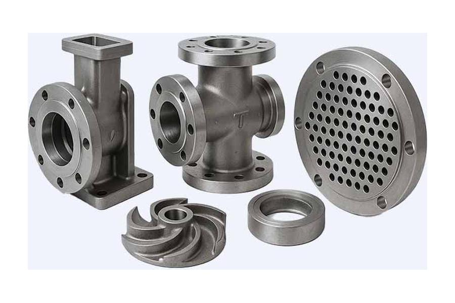
Inspection: distinguish geometry, material, and surface acceptance
A complete release plan separates the questions being answered. Dimensional inspection establishes size and geometric relationships. Material testing establishes specified material characteristics. Surface examination addresses relevant discontinuities or contamination conditions. Passing one category does not automatically demonstrate compliance in the others.
Measure geometry in the correct physical condition
Allow for temperature differences when evaluating close dimensions. The part, measuring equipment, and reference conditions need to be suitable for the required accuracy. A warm component taken directly from machining can produce a misleading comparison with a dimension measured after it has stabilized.
For flexible parts, define whether acceptance is in the free state or under specified restraint. Include the support condition in the inspection instruction where it affects the result. A coordinate report should reference the drawing’s datum scheme rather than an arbitrary best fit that hides a functional misalignment.
Measure critical features after the operations that can change them. If a later treatment, repair, or heavy stock-removal step occurs after inspection, decide which checks need repeating. A report from an earlier manufacturing stage should not be presented as evidence for a final condition it did not measure.
Choose examinations that answer the specified question
Where nondestructive examination is required, define the method, coverage, acceptance criteria, and manufacturing stage. Surface examination and volumetric examination address different types of evidence. The selected method also needs to be suitable for the material and component geometry; a generic instruction to “check for defects” is incomplete.
Phase-balance or microstructural requirements need an agreed method and sampling basis. A single convenient reading may not represent every section or condition of a complex casting. The purchase requirements should identify what must be demonstrated and how the result will be linked to the supplied part.
Compare report identifiers with the component markings and lot records. Traceability is especially important when several similar grades or heat-treatment batches move through the same workshop. Clear identification prevents an otherwise complete inspection package from becoming disconnected from the physical item.
Release: connect manufacturing records to the purchase requirement
Before shipment, review the package as a buyer would. Can the material record be traced to the part? Are the critical dimensions reported against the current drawing revision? Are required examinations complete? Are deviations, repairs, or agreed concessions visible rather than hidden in informal workshop notes?
A useful RFQ identifies the exact grade and product form, delivery condition, finished drawing, critical interfaces, and inspection requirements. It also identifies whether the supplier is responsible for the blank, machining only, or the complete finished component. That division of responsibility affects who verifies the starting material and who resolves a problem discovered during cutting.
Ask for feedback on thin walls, deep bores, interrupted cuts, and difficult inspection access before production starts. These features can influence fixture design and machining order. Early review gives the team an opportunity to improve the route while the drawing and blank dimensions can still be adjusted deliberately.
Reliable duplex machining starts with verified material and a stable process. Specify the finished condition and inspection evidence, and develop the machining route around the actual component geometry.