
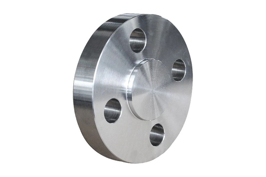
A flange can have correctly sized bolt holes and still refuse to assemble. The holes may sit on the wrong pitch circle, the pattern may be rotated relative to a locating feature, or the axes may lean enough to obstruct the fasteners through the component thickness. Bolt-hole position tolerances address relationships that a diameter check alone cannot establish.
The most useful drawing begins with how the assembly locates. It then connects the hole pattern to those functional references and allocates enough clearance for the mating parts. This article follows that sequence, using a simplified numerical example to show why hole size, position, and assembly freedom need to be considered together.
Why correct hole diameters do not guarantee assembly
Imagine two discs that must bolt together after a central pilot engages. Every clearance hole accepts an individual plug gauge, yet several bolts cannot pass through both discs. The plug test establishes something about each local hole size. It does not establish that corresponding holes occupy compatible positions once the pilot fixes the discs relative to each other.
The same problem can appear when the first bolt enters but the remaining bolts do not. Inserting that bolt may shift or rotate a loosely located part into one favorable position while making another pair of holes incompatible. Forcing the remaining fasteners into place can introduce unintended contact and hide the dimensional cause.
For forged flanges, distinguish the bolt pattern from the surfaces that provide sealing, centering, and load transfer. A bolt hole may primarily provide clearance, while a pilot controls radial location and a mating face controls seating. The drawing should preserve those different functions instead of using the hole pattern to compensate for an undefined locating system.
Establish how the flange is actually located
The seating face establishes an essential reference
A mounting face often provides the first functional reference because it seats against the mating part. Its condition affects orientation. Burrs, damage, or excessive form error can prevent repeatable seating, which can then alter the apparent relationship of the hole axes to the assembly.
Choosing a datum is an engineering decision, not simply a decision about which surface is convenient to touch with a probe. The datum scheme should represent the functional constraints in the assembly. The inspection setup must then establish those references in a way that follows the drawing’s governing tolerancing system.
Decide what centers the parts and what clocks them
A cylindrical pilot or bore may provide radial location. A separate hole, slot, key, or other feature may establish angular orientation. Some assemblies deliberately allow rotation before tightening and do not require a separate clocking feature. The drawing should reflect the actual freedom instead of constraining rotation unnecessarily.
Do not assume the outside diameter is a functional center merely because it is easy to machine. A disc can have a rough or nonlocating outside diameter while its bore and bolt pattern require a close relationship. If the inspection references the outside diameter but the assembly references the bore, the reported result may answer the wrong question.
Review the mating drawing at the same time. A consistent datum concept across the pair makes the clearance analysis more understandable. If each component is inspected against unrelated references, individually acceptable reports can still leave the assembled relationship uncertain.
Build the hole pattern from basic geometry
A circular pattern needs an unambiguous definition of its count, nominal locations, angular spacing, and orientation where orientation matters. A note giving only a pitch-circle diameter and a quantity can be incomplete if the starting angle relative to another feature controls assembly.
Within an appropriate geometric tolerancing scheme, basic dimensions describe the theoretically exact locations and a position control defines the permitted variation. This separates the ideal pattern from the allowable manufacturing departure. State the applicable standard and edition so the meaning of symbols and modifiers is agreed.
A drawing based on independent plus-or-minus coordinates can create a different tolerance zone from a diametrical position control. Replacing one scheme with another requires a geometric review; copying the same numerical value into a different symbol does not preserve the same acceptance boundary.
Also define whether the pattern must maintain a close internal relationship while allowing a different amount of movement relative to the broader datum system. More advanced pattern controls may be appropriate, but they should be selected and interpreted by the responsible designer. Complexity on the drawing is useful only when it expresses a real functional requirement.
A clearance example that exposes the tolerance budget
Consider an illustrative pair of plates with one corresponding clearance hole in each. Assume both holes have a minimum diameter of 11.0 mm and the fastener has a maximum diameter of 10.0 mm. Assume the hole axes are parallel, the fastener is free to float through both holes, and other assembly constraints are temporarily ignored.
Each hole provides 0.5 mm of radial clearance around that ideal fastener. The two hole centers can therefore be separated by up to 1.0 mm in this simplified cross-sectional model before there is no common location for the fastener center. At the limiting condition, the theoretical clearance margin is exhausted; it is not a desirable practical assembly target.
Now suppose each part has a diametrical position tolerance of 0.6 mm for that hole under the assumed common reference relationship. Each axis can be displaced radially by up to 0.3 mm. Opposing displacements can create a 0.6 mm center separation, leaving 0.4 mm of center-separation allowance in the simplified model.
| Illustrative input | Value | Meaning in the simplified model |
| Minimum clearance-hole diameter in each plate | 11.0 mm | Available hole size at the tightest limit |
| Maximum fastener diameter | 10.0 mm | Largest assumed passing diameter |
| Radial clearance in each hole | 0.5 mm | Half the diametrical size difference |
| Maximum opposing axis displacement | 0.6 mm | Two radial position allowances of 0.3 mm |
This example is a geometric illustration, not a recommended flange tolerance. It does not include fastener tilt, multiple-hole compatibility, datum variation, coating thickness, burrs, or a fixed threaded fastener. Those conditions can change the available assembly margin. A complete pattern cannot be approved by checking one favorable hole pair alone.
In a fixed-fastener arrangement, such as a bolt entering a tapped component, the fastener cannot be treated as freely floating between two clearance holes. The thread location and orientation constrain its axis. Use the appropriate fixed-fastener tolerance analysis instead of transferring the floating example unchanged.
Where a material-condition modifier is selected, the permitted geometric variation may depend on actual feature size under the governing standard. That can support functional acceptance, but only when the size limits, tolerance, and datum interpretation are coordinated. Do not add a modifier merely to make an inspection result pass.
Check orientation across the full engagement
A hole can appear correctly located at its entrance while its axis deviates through the part thickness. The longer the engagement path, the more important that orientation becomes. A shallow measurement or a single surface-center calculation may miss the condition that obstructs a long bolt or stud.
For a threaded feature carrying a projecting stud, the relationship beyond the component surface can also matter. A projected tolerance zone may be appropriate when selected by the designer to address that function. Its height and application must be stated clearly; it is not a general requirement for every flange hole.
Counterbores, spotfaces, and washers introduce additional seating considerations. The fastener may pass through the hole while its head fails to seat correctly against the intended surface. Include these features in the review where their location, orientation, or access affects assembly and load introduction.
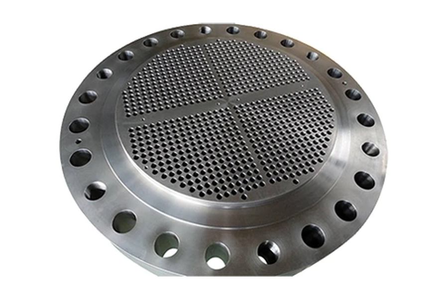
For machined forged discs with dense hole arrangements, consider the full pattern and the part’s stiffness during manufacturing. Drilling sequence, support, and clamping can influence the resulting geometry. A dense pattern also requires a clear inspection plan so that sampling does not omit the features most likely to reveal process variation.
Inspect the pattern without hiding its errors
Inspection should begin by establishing the specified datums. A coordinate measuring machine can then evaluate the hole axes and pattern against that reference system. An unconstrained best fit that minimizes the apparent pattern error may hide a location or clocking error relative to the actual assembly references.
Sampling must suit the feature. Measuring too few points or too little depth can produce an incomplete representation of a hole axis. The report should identify the relevant size and position results and explain any evaluation choice that materially affects acceptance. Numerical output is useful only when it corresponds to the drawing requirement.
A functional gauge can provide efficient evidence of assembly compatibility when it is designed for the applicable boundaries and datum conditions. It does not automatically reveal which hole caused a failure or how much individual variation occurred. Coordinate results and functional gauging can therefore serve different, complementary purposes.
Maintain the intended free-state or restrained condition during inspection. A thin disc that is pulled flat against a fixture may show different geometry after release. If restraint is part of the acceptance method, it should be defined. Otherwise, fixture pressure can conceal a condition that reappears during assembly.
Resolve a failed assembly through evidence
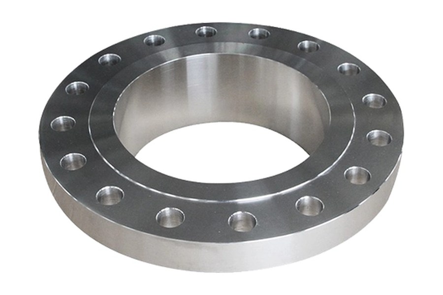
When bolts will not enter, preserve the relationship between the mating parts before reworking anything. Record which holes fail, whether the pilot has seated, and whether rotating one component changes the result. That information helps distinguish a pattern clocking error, a centering problem, or local hole variation.
Check the simplest physical obstructions first: burrs, protective coatings, debris, damaged threads, and incorrect fasteners. Then compare the actual component measurements with the current drawings. A fastener substituted during maintenance may have a different passing diameter or head geometry even when its nominal thread designation appears familiar.
Do not enlarge holes immediately to make the assembly fit. Added clearance can affect edge distance, washer seating, slip behavior, or a deliberately locating feature. If a dimensional concession is technically acceptable, document the revised condition and approval through the normal engineering process.
Distinguish a nonconforming part from an inadequate tolerance allocation. If both components meet their drawings but the assembly does not work, the drawing relationship may need correction. If one part exceeds its limits, manufacturing corrective action should address the actual source rather than quietly widening both drawings.
Prepare the drawing package for production
Specify the condition of the holes after any coating or surface treatment. A hole accepted before coating may offer less clearance afterward, and uneven deposits can affect seating features. If masking or a final sizing operation is required, make that part of the manufacturing route. The inspection report should identify the condition actually measured so the buyer can relate it to the delivered assembly.
Check drawing readability as well as technical completeness. Similar patterns on opposite faces need clear identification, particularly when only one face contains counterbores or threaded features. A correct tolerance attached to an ambiguous feature can still produce the wrong part.
A practical release review should answer how the components seat, how they center, whether they require clocking, and whether the fasteners float or are constrained. Confirm that the pattern definition, size limits, geometric controls, and inspection method all describe the same assembly logic.
- Functional references: Identify the mounting face, centering feature, and any required angular locator.
- Pattern definition: State hole count, basic locations, spacing, and orientation where applicable.
- Fastener condition: Distinguish clearance holes, threaded holes, studs, and any locating fasteners.
- Manufacturing stage: Define acceptance after the relevant machining, treatment, and coating operations.
- Verification: Agree datum establishment, sampling coverage, and required inspection records.
For repeat production, retain the first-article results and the agreed interpretation of the pattern controls. A change in fixture, machining sequence, or inspection program should be reviewed against those requirements. This prevents a process change from silently altering how the drawing is applied.
Make interchangeability an explicit goal if replacement flanges must mate with existing equipment. An assembly trial using one selected pair provides limited evidence about future combinations. The tolerance analysis and acceptance method should support the allowed production range and the installed mating conditions.
Define bolt-hole position around the assembly’s locating features and available clearance. Verify the complete pattern so that correct hole diameters also translate into reliable assembly.