
A keyed connection is often a practical choice when positive torque engagement and planned disassembly are important. An interference fit can suit applications that need torque transfer through continuous surface contact without a keyway, provided the contact pressure, material stresses, and assembly procedure are properly engineered. Neither option is universally stronger, easier to maintain, or more accurate.
The useful comparison is between complete connection designs. A key does not eliminate the need to specify the shaft-to-bore fit, and an interference fit does not eliminate the need to check fatigue, axial loads, or removal. This selection guide uses a series of design gates so buyers can identify the requirements that should control the decision.
Define what the connection has to do
Before comparing manufacturing methods, describe the job of the interface. It may have to transmit steady torque, survive frequent reversals, maintain angular registration, locate a rotating component, resist axial movement, or allow repeated servicing. List these functions separately, even when one interface must satisfy several of them simultaneously.
A conventional parallel key transfers torque through its engagement with the shaft and hub keyways. The surrounding cylindrical fit still influences centering and movement. A keyed assembly with excessive clearance can behave poorly even when the key itself has sufficient nominal strength. The quality of the complete interface matters more than the presence of a familiar feature.
In an interference fit, the dimensional overlap between mating parts develops contact pressure after assembly. Friction at the interface resists relative motion. Pressing and thermal assembly are ways of creating that assembled condition; they are not separate proof that the resulting joint has the required capacity.
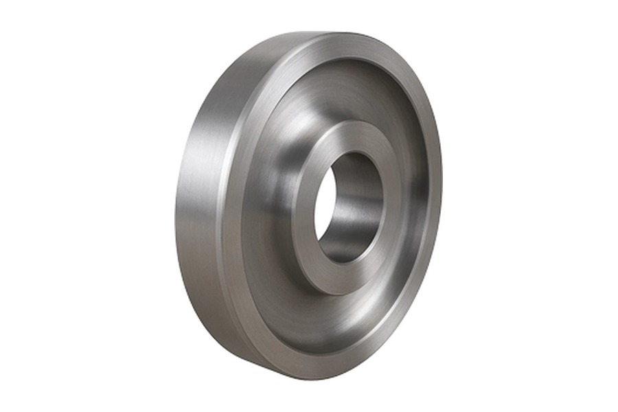
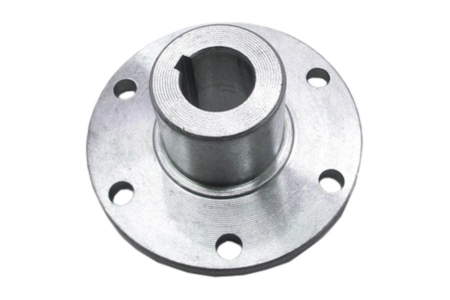
For forged hub components, review the actual bore length, wall thickness, flange transitions, and access for installation. Two hubs with the same nominal bore can respond differently because their surrounding geometry is different. Use the complete finished shaft and hub geometry to make the choice; bore diameter by itself is insufficient.
Gate one: understand the torque and fatigue duty
Begin with the load history rather than average power
Steady running torque is only one part of the duty. Starting, braking, reversing, impact events, and process jams may produce more demanding conditions. The number and severity of load cycles also influence fatigue assessment. Record the operating cases the connection must withstand and identify which ones govern the design.
A keyway introduces a geometric discontinuity in the shaft and hub. Local stresses depend on the feature shape, end details, material, surface condition, and combined loading. A simple check of key shear does not establish the fatigue strength of the surrounding shaft. This becomes particularly relevant when bending and reversing torque act together.
An interference connection avoids that particular keyway discontinuity if no keyway is present, but it introduces interface pressure and associated stresses. The ends of the contact region and changes in section deserve attention. It is therefore inaccurate to describe a keyless interference joint as free from fatigue concerns.
Check how the joint behaves before gross slip
For a keyed arrangement, clearance and contact distribution affect how torque reaches the loaded flank. Reversing duty can shift the loaded side and expose backlash or impact. The selected key fit, shaft-to-bore fit, and manufacturing quality should reflect whether that movement is acceptable for the application.
For a friction joint, the engineer needs a credible basis for interface friction and contact pressure. Surface finish, preparation, and permitted assembly substances influence those assumptions. A calculated capacity using an optimistic friction value is not a substitute for a defined manufacturing and assembly condition.
Combined torque and axial force also need a combined assessment. A friction interface that carries both does not necessarily offer its full separate torque and axial capacities simultaneously. Similarly, a key intended to transmit torque should not be assumed to supply the complete axial retention system. Identify the additional retaining features wherever they are required.
If the machine requires a repeatable angular relationship, state that requirement explicitly. A keyway can provide an indexing feature, but its tolerances and assembly clearances affect the achieved relationship. A plain interference fit requires another means of establishing angular position before the joint locks. Neither choice automatically guarantees a precise phase relationship.
Gate two: check geometry and material limits
Inspect the available section around the bore. A thin hub wall may constrain the acceptable interference, while a deep or wide keyway removes material from the load-bearing section. The design needs enough material for the selected mechanism and for the other loads transmitted through the hub body.
A longer engagement can change torque capacity, but it also affects machining, seating, and assembly. Actual contact may not be uniform if the bore is tapered or the shaft has form error. Treat the effective interface as a manufactured surface with measurable variation, rather than assuming perfect contact over every nominal millimeter.
Specify the material condition as well as the grade
Strength and ductility depend on the supplied material condition. Heat treatment, hardness, section size, and any surface treatment can affect the design checks and machining route. A material name on a quotation should be connected to the required delivery specification and the condition in which the finished dimensions will be accepted.
For an interference design, differential thermal expansion can alter the contact condition during service. The hub and shaft may reach different temperatures even when they are made from similar materials. Evaluate the relevant temperature combinations rather than using one ambient measurement as evidence for every operating condition.
For a keyed design, hardness differences and surface quality can influence how the key and keyway flanks wear. The weakest or most damage-prone region may be in the hub or shaft rather than in the replaceable key. Choosing an extremely strong key does not automatically improve the durability of the assembly.
Include geometry controls beyond diameter
A diameter tolerance describes an allowed size range, but the assembled connection also depends on form, alignment, and surface condition. Review the bore and shaft over their working lengths. Where rotation is important, relate the mounting interface to the functional datum features instead of specifying isolated dimensions without their geometric relationships.
On machined forged shafts, the manufacturing route should preserve sufficient stock for the final journals and connection surfaces. A keyway, finish grind, or heat treatment introduced late in the route may influence how the supplier maintains the final geometry. Share the connection requirements before the blank and machining sequence are finalized.
Gate three: plan assembly and future removal
Installation equipment can decide which option is practical
A keyed connection may be convenient where technicians need to install and remove a hub with ordinary workshop access. That advantage depends on the selected cylindrical fit. A keyed assembly can still be difficult to separate if the fit is tight, corrosion develops, or the extraction arrangement was never designed.
A press-assembled interference joint needs controlled alignment, suitable force application, and an appropriate support path. The component must not be driven into place through a bearing or feature that was not designed for that force. An unexpectedly high pressing force can indicate misalignment, damage, or unsuitable conditions rather than extra assurance of quality.
Thermal assembly requires a controlled temperature procedure, sufficient installation clearance, and a plan for completing seating before temperatures equalize. The allowable temperature depends on the material condition, treatments, and any adjacent components. A universal heating temperature is not appropriate for every shaft–hub design.
In both methods, define surface preparation and permitted lubrication. If the design calculation assumes a particular contact condition, the shop instruction must produce that condition consistently. A last-minute substitution of lubricant or cleaning method can change the interface behavior while leaving the drawing dimensions unchanged.
Removal should be designed before the first installation
Ask how force will be applied during disassembly and where the extracted component can move. Provide access for approved pulling or thermal methods where required. A nominally serviceable joint can become impractical if the surrounding housing blocks the extraction path or if there is no suitable reaction surface.
Repeated removal changes the decision. A key can be replaced, but the bore and keyways still require inspection. An interference interface may experience scoring or dimensional change during separation and reassembly. The maintenance plan should state what is measured, which damage is unacceptable, and when components must be replaced.
Where interchangeability matters, evaluate the tolerance range across all approved replacement parts. A favorable fit between one measured shaft and one measured hub does not prove that any future pair will behave the same way. If selective assembly is part of the solution, the identification and matching process becomes a controlled requirement.
Compare the options against your actual constraints
The following comparison is a review aid, not a universal ranking. Use it after the loading, geometry, and maintenance gates have been considered. An unresolved condition in one row can outweigh several apparent advantages elsewhere.
| Decision factor | Keyed connection | Interference connection |
| Torque transfer | Depends on key engagement and surrounding component strength | Depends on interface pressure, friction, and effective contact |
| Fatigue review | Include keyway geometry and combined shaft loading | Include contact stresses and interface-end behavior |
| Angular positioning | Can use keyway geometry as a locating feature | Requires an assembly reference if phase matters |
| Installation | Depends on cylindrical fit and key seating | Requires a controlled pressing or thermal procedure |
| Maintenance | Review access, wear, and the condition of both keyways | Review removal method and interface condition before reuse |
For example, a hypothetical frequently serviced drive with moderate reversing duty might favor a keyed arrangement, but only after backlash and fatigue are checked. A compact assembly with a suitable hub section and controlled factory installation might favor interference, but only after stress, temperature, and removal requirements are resolved. These examples describe decision logic rather than validated designs.
A hybrid arrangement also needs a clear purpose. Combining a key with an interference fit can be appropriate in a designed system, but it adds machining and inspection requirements. State whether the key provides indexing, backup engagement, or a defined share of torque transmission. Avoid leaving that role to assumptions made independently by the designer and assembler.
When neither option satisfies the constraints, reconsider the connection architecture. The correct outcome of a selection review may be a different shaft–hub mechanism or a changed component layout. Forcing a familiar connection into an unsuitable envelope can create recurring maintenance problems that a small drawing change cannot solve.
Release a complete connection specification
Inspection evidence should match the chosen mechanism. A keyed design benefits from records that establish the working flank geometry and the relationship between the bore and keyway. An interference design benefits from measured mating sizes and the relevant surface-form results. In either case, a photograph of a completed assembly cannot demonstrate the critical dimensions hidden inside it.
Agree how nonconforming components will be handled before the first assembly trial. Unapproved polishing, selective filing, or local material removal can change the intended fit and make the final condition difficult to quantify. If adjustment is permitted, define the allowed method, the dimensions to recheck, and the records needed to show that the adjusted component still satisfies its functional requirements.
The purchase package should include both mating drawings, material and heat-treatment requirements, critical surface conditions, and the intended assembly method. Identify the torque and axial duty information needed for design review without expecting the supplier to infer it from shaft diameter or motor power alone.
For keyed parts, define the key standard or complete geometry, width fits, working length, end details, and applicable clearances. Make the axial retention arrangement visible. A purchase line that says “with keyway” leaves essential geometry and acceptance decisions unresolved.
For an interference design, define the dimensional limits and the relevant geometric controls on both surfaces. Connect them to the approved material condition and assembly procedure. Specify how the finished interface will be inspected and how assembled seating or position will be confirmed.
Request manufacturing feedback before releasing production quantities. The supplier may identify tool access, inspection, or heat-treatment sequence issues that are inexpensive to resolve at drawing review. Any agreed change should be incorporated into the controlled specification so later batches do not depend on an informal conversation.
Record why the connection suits the application and which operating assumptions support that choice. This gives future maintenance and purchasing teams a clear basis for selecting replacements.