
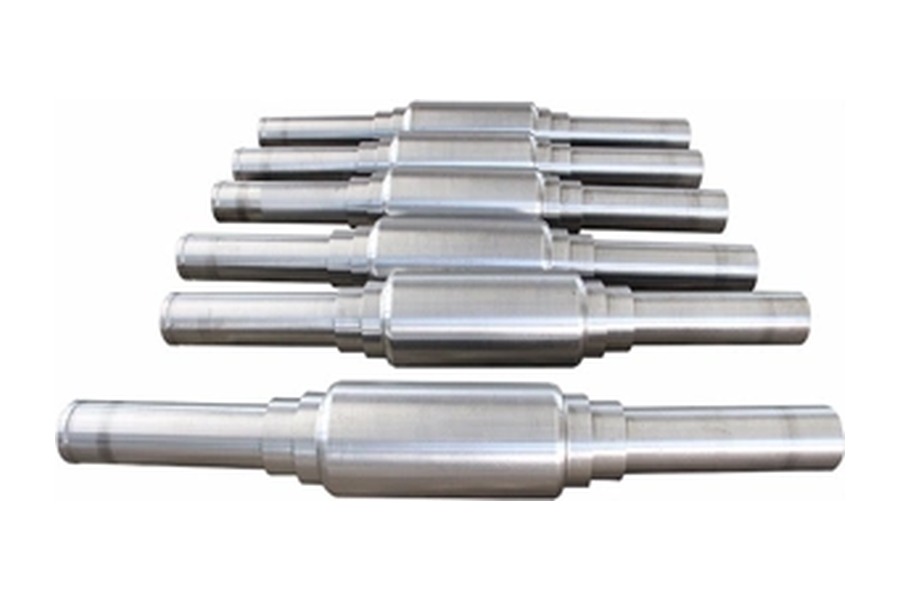
Buyers should specify straightness when they need to limit the bending or line-form error of a shaft feature, and runout when they need to limit how a surface moves relative to a defined rotational datum. Many working shafts need both types of control, but the requirements must apply to identified features. A note that simply asks for a shaft to be “straight and concentric” leaves too much open to interpretation.
The practical choice starts with the assembly. A long shaft passing through several supports presents a different problem from a short shaft carrying a tightly positioned seal sleeve. The drawing should explain which surfaces support rotation, which surfaces must remain aligned with them, and which sections may tolerate larger manufacturing variation. This guide turns those functional questions into a specification that a buyer, machinist, and inspector can discuss consistently.
Start with the failure the drawing must prevent
Consider the consequences of movement before selecting a tolerance symbol. A bent intermediate span can reduce clearance inside a housing. A bearing seat that rotates eccentrically relative to another seat can disturb alignment. A shoulder that wobbles can prevent a mounted component from seating consistently. These problems may occur on the same part, yet they do not have the same measurement requirement.
When reviewing forged shafts for machining, separate the blank requirements from the requirements on the finished working surfaces. A forging may need sufficient stock to clean up around the intended axis. The finished shaft may need a much closer relationship between its journals and mounting surfaces. Applying the finished runout requirement to an unfinished forging can create unnecessary rejection without improving the delivered assembly.
Write down the operating condition as well. An unloaded inspection at room temperature cannot describe every deflection that occurs under torque, radial load, or a thermal gradient. Drawing tolerances control manufactured geometry under a defined inspection condition. Structural stiffness, bearing arrangement, and operating balance still require their own engineering assessment.
Straightness and runout answer different questions
Straightness concerns the shape of the specified feature
Surface straightness limits the departure of an individual line element from a straight line. On a cylindrical shaft, this may relate to a longitudinal line along the outside surface. A control applied to a derived median line addresses a different geometric feature. The drawing attachment and tolerance-zone definition therefore matter; the word “straightness” alone does not say which interpretation is intended.
As a form requirement, straightness evaluates the specified feature without using another feature to establish its reference axis. A feature can satisfy a straightness requirement while being tilted or offset relative to a different journal. That distinction is especially important when buyers try to use one straightness note to guarantee that several bearing seats share the intended rotational relationship.
Runout concerns a surface relative to a datum
Circular runout evaluates the variation of a controlled surface at individual circular sections as the part rotates about the specified datum axis. Total runout extends the assessment across the controlled surface. For a cylindrical feature, the difference affects whether the requirement addresses each section separately or the combined surface relationship over its length.
A runout reading can contain contributions from several geometric errors. It is not automatically a direct measure of shaft bend, and it does not independently identify the source of the variation. The general framework of geometric dimensioning and tolerancing helps communicate these distinctions, but the drawing must also identify the governing standard and edition.
| Control | Main purchasing question | Key specification detail |
| Surface straightness | Is the specified surface line sufficiently straight? | Controlled line direction and extent |
| Derived median line straightness | Is the feature’s median line within its permitted zone? | Feature attachment and zone definition |
| Circular runout | How much does each section vary during rotation? | Datum axis and controlled surface |
| Total runout | How much does the complete controlled surface vary? | Datum establishment and full measurement coverage |
How the same shaft produces different readings
A dial indicator only reports movement at its contact point. Understanding the fixture is therefore as important as reading the dial. When a shaft is supported between centers, its rotational reference comes from those center features and the setup. When it rests on journals in a fixture, the reference comes from the supported surfaces and the way the fixture constrains them.
Those setups are not interchangeable merely because both allow rotation. If the working datum comes from finished bearing journals, a check between manufacturing centers needs an established relationship to those journals before it can demonstrate the required result. Center damage, incomplete seating, or an incorrectly prepared datum simulator can change the apparent reading.
A simple hypothetical reading
Suppose an indicator reaches a minimum of 0.01 mm and a maximum of 0.05 mm during one revolution at a selected section. The observed total indicator variation at that location is 0.04 mm. This illustrative arithmetic does not establish a suitable acceptance limit, and it does not prove that the shaft has 0.04 mm of bend.
For an ideal circular section with pure eccentricity, indicator variation can be related to the offset of its center. A real shaft can also contain roundness error, local damage, fixture movement, or surface irregularity. Dividing every shop-floor reading by two and calling the result “straightness” is therefore not a reliable inspection method.
Repeat the observation at the locations needed by the control. Measurements at two ends cannot automatically represent the entire span. A middle section may contain a local departure that the end readings miss. Conversely, a small mark on one section may create a sharp indicator peak without describing the geometry of the rest of the shaft.
Keep the measurement direction clear. Radial movement on a cylindrical journal and axial movement on a shoulder face address different functional relationships. Recording both simply as “runout” makes later acceptance discussions difficult, particularly when the shaft carries a flange, gear, or coupling against that shoulder.
Choose controls around the working interfaces
Bearing journals establish the support relationship
Start with the journals that locate the shaft in service. Their diameters, form, spacing, and geometric relationship influence how the supported assembly behaves. The engineering team should decide whether one feature or a defined combination of features establishes the datum axis. The inspection plan then needs to reproduce that datum construction rather than choose whichever setup is easiest.
Do not assign equally tight controls to every outside diameter by habit. A clearance diameter between bearings may have a different function from a precision mounting seat. Identify where the tolerance protects bearing alignment, housing clearance, or another measurable requirement. This makes the drawing more understandable and helps suppliers plan the machining sequence.
Mounting seats and shoulders need their own review
A hub seat may require a controlled fit as well as an appropriate geometric relationship to the support journals. Diameter tolerance defines the size range, but size alone does not establish acceptable surface form or runout. The selected controls need to work together without contradictory notes.
The shoulder determines where a component stops axially and can affect how that component sits on the shaft. Face runout may be relevant where rotation exposes axial variation, while a different orientation control may be appropriate for another function. Buyers should ask the designer to express the intended interface instead of substituting one symbol because it appears easier to inspect.
When the shaft mates with custom forged hubs, review the shaft and hub drawings together. A close shaft tolerance cannot compensate for an unsuitable bore, damaged contact face, or incomplete seating. The assembly result depends on both components and on the locating method used during installation.
Long or slender sections require a support condition
Gravity and support placement can influence readings on a slender shaft. A measurement taken horizontally on widely separated supports may differ from one obtained with a different support arrangement. This does not mean either result is automatically wrong; it means the inspection condition needs to be defined well enough to connect the result to the requirement.
If straightening is permitted during manufacture, agree when it may occur and what checks follow it. A part that passes before heat treatment or before the last heavy machining operation may change afterward. The purchasing document should make clear whether acceptance applies to the finished, treated, and cleaned component.
Agree on a measurement plan before production
An inspection plan should describe the controlled feature, datum establishment, instrument, coverage, and reporting method. It should also identify conditions that can influence the result, such as temperature, support forces, or the presence of protective coatings. A statement that the supplier will use a “precision instrument” is not enough to settle these questions.
For rotational checks, explain where the indicator contacts the surface and how the required span is covered. For coordinate measurements, explain how the relevant features are sampled and evaluated. The inspection method must be appropriate to the specified control; a convenient software output should not silently replace the drawing requirement.
Measurement uncertainty deserves attention when the tolerance is close to the practical capability of the setup. Instrument resolution is only one contributor. Repeatability, fixturing, surface condition, alignment, and evaluation choices can all influence the reported result. Agree on the acceptance decision rule when results near the limit could become disputed.
- Reference features: Identify the exact datum surfaces and their order or combined relationship.
- Measurement coverage: State the relevant sections, length, and circumferential coverage.
- Part condition: Define the manufacturing stage, cleanliness, temperature condition, and support arrangement.
- Result format: Request numerical results tied to drawing characteristics, rather than a general pass statement alone.
- Disagreement process: Establish how the parties will reproduce a disputed measurement using the same interpretation.
A first-article review can expose interpretation differences before a batch is complete. Ask for the setup description alongside the values for critical characteristics. If the fixture uses temporary manufacturing features, the supplier should explain why that setup represents the functional datum requirement. This is particularly useful when one organization machines the shaft and another performs final acceptance.
Turn a tolerance discussion into a purchasing specification
Provide the current drawing, material condition, machining stage, and mating-component details. Identify the features requiring straightness or runout control, their functional datums, and the agreed inspection method.
Before ordering, confirm that the supplier can maintain these requirements through machining, heat treatment, and handling. Keep approved drawings and inspection records consistent across repeat orders.