Flanges ensure secure piping connections, sealing, and maintenance access. Lap joint and weld neck flanges are widely used, differing in design, function, and application suitability.
Overview of Lap Joint Flanges
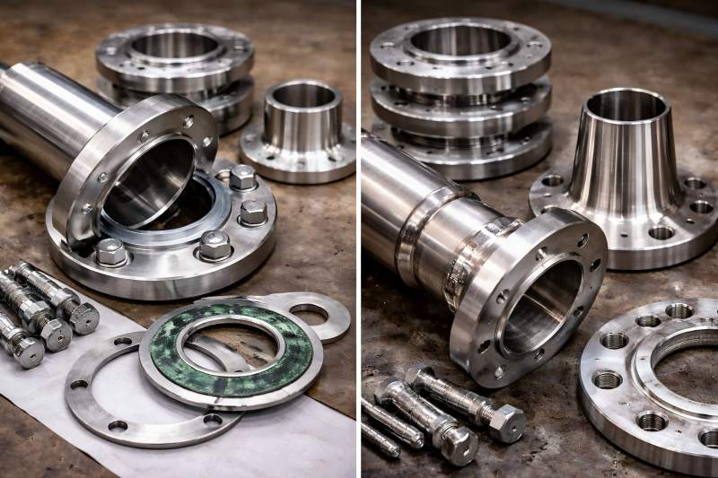
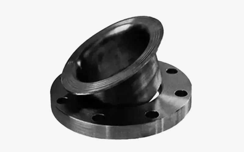
Lap joint flanges, also known as loose flanges, are two-piece flanges consisting of a flange ring and a stub end. The stub end welds; the flange slides freely for rotation. This design provides alignment flexibility, making lap joint flanges ideal for pipelines requiring frequent inspection, maintenance, or repositioning.
Key Features of Lap Joint Flanges:
- Two-piece design: flange + stub end
- Flange can rotate around the stub end
- Often used with low-cost flange materials
- Compatible with corrosive fluids if the stub end is corrosion-resistant
| Pros | Cons |
| Easy alignment during assembly | Not ideal for high-pressure systems unless high-strength materials are used |
| Simplified inspection and disassembly | Requires both a flange and stub end, increasing inventory complexity |
| Reduced material costs for large pipelines | |
| Minimal stress on bolts during tightening |
Overview of Weld Neck Flanges
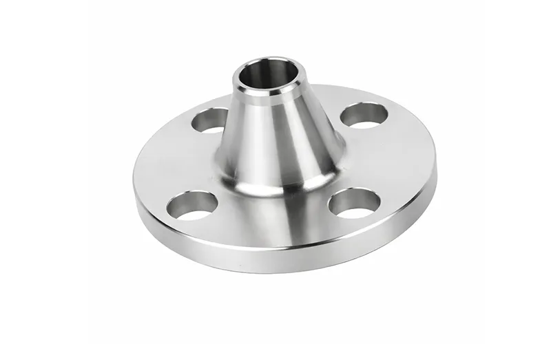
Weld neck flanges have a tapered hub welded to the pipe for high-pressure, high-temperature applications. This design ensures strength, durability, and excellent stress distribution across the joint.
Key Features of Weld Neck Flanges:
- Butt-welded directly to the pipe
- Designed for high-pressure and high-temperature systems
- Offered in RF, FF, and RTJ flange face types.
| Pros | Cons |
| High structural integrity and durability | Higher initial cost due to one-piece design and welding |
| Minimizes flange failure via stress distribution. | Installation is more complex than lap joint. |
| Suitable for extreme operating conditions | Alignment adjustments are limited after welding |
| Suitable for high-pressure, high-temperature pipes. | – |
Design and Structural Differences
The primary difference between lap joint and weld neck flanges lies in design and structural configuration.
Design Comparison
| Feature | Lap Joint Flange | Weld Neck Flange |
| Construction | Two-piece (flange + stub end) | One-piece with tapered hub |
| Welding | Stub end welded to pipe | Flange welded directly to pipe |
| Hub | Short or no hub | Long tapered hub |
| Rotation | Flange can rotate | No rotation |
| Stress Distribution | Moderate | Excellent, ideal for high-pressure |
| Alignment Flexibility | High | Limited after welding |
The lap joint flange’s loose design allows rotation around the stub end, making it easier to align and tighten bolts evenly.
Material Selection
Material choice is crucial to flange performance, especially in corrosive or high-temperature environments. Lap joint and weld neck flanges are available in carbon steel, stainless, alloy steel, or specialty materials. However, their design influences material selection strategy.
Material Recommendations
| Application Type | Lap Joint Flange Material | Weld Neck Flange Material |
| Water / Wastewater | Carbon Steel / Stainless | Carbon Steel / Stainless |
| Chemical / Corrosive Fluids | Stainless or Alloy Stub End | Stainless / Alloy Flange |
| High-Temperature Steam | Stainless or Carbon Steel | Stainless / Alloy Steel |
| Oil & Gas Pipelines | Corrosion-Resistant Stub End | High-Strength Alloy Steel |
| Food / Pharmaceutical Systems | Stainless Steel Stub End | Stainless Steel |
Tip: In lap joint flanges, the stub end material is critical because it contacts the fluid. The flange itself can often be a lower-cost material. Weld neck flanges, being one-piece, require the entire flange to be made from suitable high-performance material.
Installation Differences
Installation procedures differ considerably between lap joint and weld neck flanges.
Lap Joint Flanges:
- Weld the stub end to the pipe.
- Slide the flange over the stub end.
- Align flange bolt holes and insert bolts.
Weld Neck Flanges:
- Align flange with pipe end.
- Tack weld flange hub to pipe.
- Perform full penetration butt weld along the flange hub.
- Inspect weld quality and torque bolts.
Installation Complexity
| Feature | Lap Joint Flange | Weld Neck Flange |
| Welding Requirement | Only stub end | Full flange hub |
| Alignment Flexibility | High | Low after welding |
| Assembly Time | Faster | Longer |
| Maintenance Access | Easy | Limited |
| Tools Required | Basic hand tools | Welding equipment, inspection tools |
Pressure and Temperature Suitability
Lap joint and weld neck flanges have different pressure-temperature limits.
Lap Joint Flanges:
- Ideal for low-to-medium pressure systems (ANSI Class 150–600)
- Works well under moderate temperature conditions
Weld Neck Flanges:
- High-pressure, high-temperature, critical ANSI Class 150–2500+
- Suitable for extreme temperatures and corrosive fluids.
Pressure and Temperature Comparison
| Flange Type | Typical Pressure Range | Temperature Range | Typical Use |
| Lap Joint | ANSI Class 150–600 | -20°C to 300°C | Low to medium pressure, corrosive fluid pipelines |
| Weld Neck | ANSI Class 150–2500 | -50°C to 600°C | High-pressure, high-temperature, critical systems |
Cost Considerations
Lap joint flanges are generally more cost-effective, especially for large-diameter pipes, because the flange material can be lower-cost steel and only the stub end contacts the fluid. Weld neck flanges cost more due to one-piece construction.
| Feature | Lap Joint Flange | Weld Neck Flange |
| Material Cost | Moderate | High |
| Fabrication Cost | Moderate | High (welding labor included) |
| Installation Time | Short | Long |
| Maintenance Cost | Low | Moderate |
Maintenance and Inspection
Lap Joint Flanges:
- Easy to disassemble for inspection or maintenance.
- Flange rotation allows adjustment without removing pipe welds.
- Gasket replacement is straightforward.
Weld Neck Flanges:
- One-piece construction requires pipe cutting for major maintenance.
- High structural integrity reduces frequent maintenance needs.
- Regular inspection focuses on weld integrity and gasket condition.
Maintenance Comparison
| Feature | Lap Joint Flange | Weld Neck Flange |
| Ease of Disassembly | High | Low |
| Gasket Replacement | Easy | Moderate |
| Inspection Frequency | High | Moderate |
| Repair Complexity | Low | High |
Typical Applications
Lap Joint Flanges:
- Water and wastewater pipelines
- Corrosive chemical lines
- Food and pharmaceutical systems
- Temporary or frequently disassembled piping
Weld Neck Flanges:
- High-pressure oil & gas pipelines
- Steam and high-temperature systems
- Critical chemical and petrochemical plants
- High-stress or high-vibration pipelines
Application Summary
| Flange Type | Typical Industries | System Requirements |
| Lap Joint | Water, chemicals, food & pharma | Frequent disassembly, moderate pressure |
| Weld Neck | Oil & gas, power plants, refineries | High pressure, high temperature, structural integrity |
Summary of Key Differences
| Feature | Lap Joint Flange | Weld Neck Flange |
| Construction | Two-piece | One-piece |
| Welding | Stub end only | Full flange hub |
| Rotation | Yes | No |
| Pressure | Low to medium | Medium to high |
| Temperature | Moderate | High |
| Material Consideration | Stub end critical | Entire flange critical |
| Installation Complexity | Easy | Complex |
| Maintenance | Easy | Moderate to difficult |
| Cost | Moderate | High |
Lap joint flanges excel in applications where alignment flexibility, frequent inspection, and cost savings are priorities. They are ideal for pipelines carrying corrosive fluids, low to medium pressures, or systems that require regular maintenance. Weld neck flanges, on the other hand, provide maximum structural integrity, stress distribution, and reliability in high-pressure, high-temperature, and critical applications.