
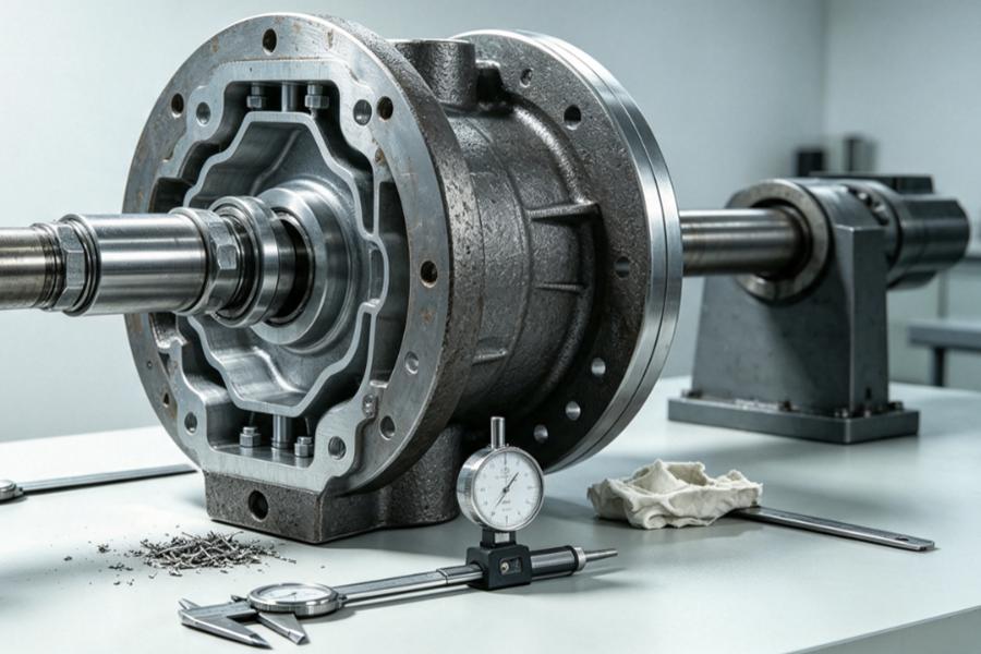
Forged hubs may meet drawing tolerances yet fail in service. Bore alignment, face runout, spline contact, shoulder geometry, and heat-treatment distortion must work together for accurate rotation and torque transfer.
Coordination of Alignment and Torque Transmission
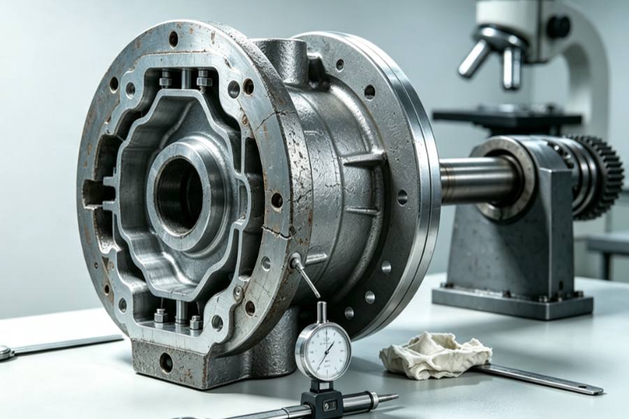
Alignment determines whether the hub rotates around the intended axis. Torque-transfer features determine how rotational force moves between the shaft, hub, flange, wheel, coupling, or driven component.
When these functions are designed independently, several problems may appear:
- Uneven spline or key contact
- Localized fretting around the bore
- Bolt loosening under reversing loads
- Edge loading on shoulders
- Excessive radial or axial runout
- Noise and vibration at operating speed
- Premature cracking near keyways or bolt holes
A reliable design normally assigns these functions clearly instead of allowing one feature to perform both jobs without sufficient control.
Establish a Clear Functional Datum
The datum system is the foundation of hub alignment. It determines how forging allowances, machining operations, inspection results, and assembly dimensions relate to one another.
Common hub datums include:
- Finished central bore
- Pilot diameter
- Mounting face
- Shaft shoulder
- Tapered seating surface
- Bearing seat
A convenient machining surface may be the wrong datum when the hub is located by its bore and mounting face.
Recommended Datum Logic
| Hub Function | Primary Datum | Secondary Datum | Controlled Feature |
| Shaft-mounted hub | Finished bore | End face | Flange and outer diameter |
| Flange-mounted hub | Pilot diameter | Mounting face | Bore and bolt circle |
| Tapered hub | Taper surface | Axial stop face | Flange position |
| Splined hub | Spline reference diameter | End face | Outer profile and bolt holes |
| Bearing hub | Bearing seat | Shoulder face | Seal and flange positions |
Critical features should be machined and inspected from the same functional datum whenever practical. This reduces datum conversion and prevents small setup errors from accumulating across several operations.
Use a Positive Locating Feature
Bolts should normally clamp the joint rather than position the hub. Depending only on bolt clearance holes for alignment allows the hub to move before or during tightening.
A positive locating structure provides more repeatable assembly.
Locating Methods
- Pilot Diameter
A machined pilot centers the hub relative to the mating component. It is suitable for flanged connections, wheel hubs, couplings, and gearbox assemblies.
- Shaft Shoulder
The shoulder controls axial position and provides a stable seating surface. Its corner radius must remain compatible with the hub chamfer or relief groove.
- Cylindrical Fit
A controlled bore-to-shaft fit provides direct radial positioning. The fit should reflect assembly frequency, operating temperature, load direction, and maintenance requirements.
- Tapered Fit
Tapers deliver accurate positioning and high friction torque capacity, yet surface finish, contact area, axial fastening load and demounting needs must be carefully managed.
- Serrated or Face-Tooth Location
Radial face teeth or serrations can provide both angular positioning and torque transfer. Their performance depends heavily on tooth contact and clamping force.
Improve the Bore and Shaft Interface
Bore roundness, cylindricity, surface condition, and relationship to the mounting face all affect final rotation.
Simply applying a tight diameter tolerance does not guarantee good alignment. A bore may be within size limits but still have taper, lobing, or axis deviation.
Key bore controls include:
- Diameter and fit
- Roundness
- Cylindricity
- Straightness
- Surface roughness
- Bore-to-face perpendicularity
- Bore-to-flange concentricity
- Chamfer and relief geometry
Frequently mounted hubs benefit more from transition fits or removable positioning instead of over-tight interference fits. Excess interference boosts assembly effort, warps thin hub parts and creates maintenance difficulties.
Select the Right Torque-Transfer Feature
| Torque Feature | Alignment | Best Use |
| Key | Limited | Moderate torque |
| Spline | Good | High or repeated torque |
| Taper Fit | High | Compact precision joints |
| Face Serration | High | Indexed connections |
| Friction Face | Pilot required | Flange joints |
| Cross Pin | Limited | Light-duty retention |
Larger keys can weaken hubs, while splines improve torque distribution only when alignment ensures consistent contact across the engagement length.
Control Spline and Key Contact
Spline geometry requires more than tooth size inspection. Lead error, pitch variation, tooth profile, bore position, and heat-treatment distortion can change the actual contact pattern.
Important spline checks include:
- Effective tooth thickness
- Major and minor diameters
- Pitch accuracy
- Tooth lead
- Profile condition
- Engagement length
- Contact pattern
- Concentricity with the mounting face
Machine the keyseat from the finished bore; side faces transfer torque, while fit prevents impact loading and ensures shaft seating.
Design the Forging Around the Torque Path
Smooth geometric transitions are essential for forged hubs. Sharp profile changes, thin ribs, deep key slots and tightly spaced bolt holes interfere with torque transmission and shorten service life.
Useful forging design measures include:
- Smooth bore-to-web transitions
- Adequate fillet radii
- Balanced flange thickness
- Sufficient material around splines and keyways
- Gradual changes between thick and thin sections
- Machining allowance on all functional surfaces
- Symmetrical preform design where possible
Manage Heat-Treatment Distortion
Thermal processing may deform bores, end faces, bolt hole arrays and splines. To guarantee precise alignment, balance wall thicknesses, reserve machining stock, regulate heating and quenching, then machine key datum planes after measuring deformation.
Control the Mounting Face and Bolt Circle
Mounting faces control axial alignment, while pilots or bores control radial alignment; both require perpendicularity and fit to prevent runout.
Important controls include:
- Face flatness
- Face-to-bore perpendicularity
- Axial runout
- Bolt-circle position
- Hole spacing consistency
- Pilot-to-bolt-circle concentricity
- Seating surface finish
- Local burr and damage control
Maintain Stable Clamping Force
Consistent bolt preload, flush contact surfaces, clean seats and matched pilot gaps are mandatory for reliable torque transfer. Upgraded bolts cannot stop slip, fretting, loosening or stretched holes with reversed cyclic loads.
Considerations
Operating Torque
Peak torque, reversing torque, shock loading, and start-stop frequency may be more important than average operating torque. The connection should be evaluated against the actual load pattern.
Rotational Speed
As speed increases, small alignment errors become more noticeable. Runout, mass imbalance, and face position need tighter coordination.
Assembly Method
Press fitting, thermal fitting, hydraulic installation, manual assembly, and field replacement require different bore fits and lead-in structures.
Maintenance Frequency
A permanent interference fit may be acceptable for a non-serviceable assembly. Detachable hubs require a different balance between positioning accuracy and removal convenience.
Material and Heat Treatment
The hub material must provide adequate strength around the bore, spline, keyway, bolt holes, and web transitions. Hardness should support wear resistance without making critical sections unnecessarily brittle.
Production Volume
For repeated orders, dedicated fixtures and functional gauges can improve consistency. For low-volume Custom parts, flexible inspection methods and carefully defined datum instructions may provide better overall value.
Improvement Guide
| Hub Condition | Recommended Focus |
| Shaft-mounted keyed hub | Bore fit, shoulder seating, and key side contact |
| High-torque splined hub | Spline contact, root strength, and heat-treatment distortion |
| Flanged coupling hub | Pilot location, face runout, and bolt preload |
| High-speed rotating hub | Concentric machining, balance, and axial runout |
| Reversible-drive hub | Distributed torque contact and anti-fretting measures |
| Frequently removed hub | Repeatable location with controlled assembly clearance |
| Large forged hub | Section balance, datum stability, and machining setup |
| Thin-web hub | Distortion control and gradual load transitions |
Better forged hub performance comes from one functional axis, separate alignment and torque paths, controlled distortion, and assembled-load inspection accuracy.