
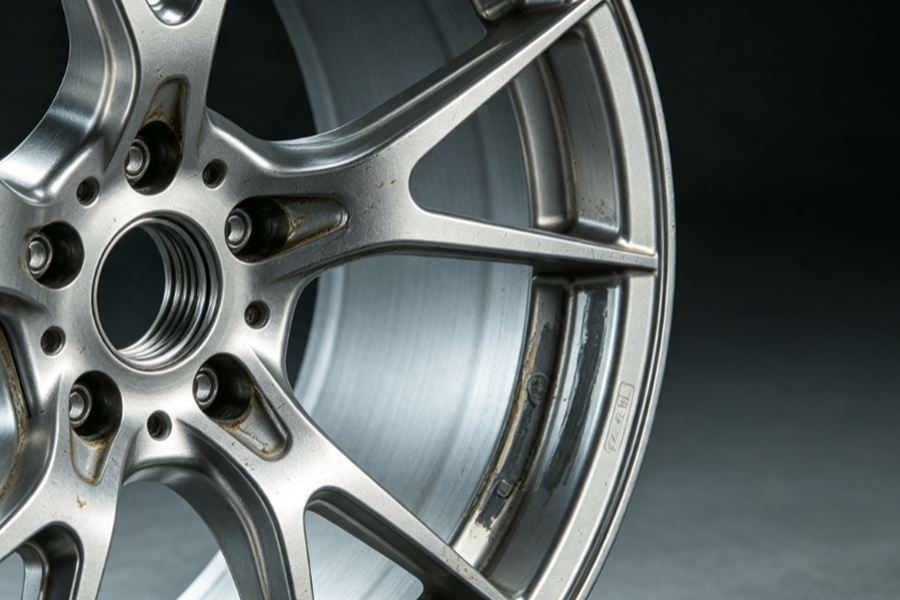
Forged wheels offer high strength, but repeated loads, heat, impacts, corrosion, and improper repairs reduce fatigue life. Repair decisions should prioritize predictable remaining service life, not appearance alone or cost.
Fatigue Life in a Forged Wheel
When speaking of fatigue life, it represents the quantity of recurring load cycles a wheel is capable of resisting before cracks develop or propagate to an unqualified size.
A forged wheel normally experiences several types of cyclic loading:
- Radial load: Vehicle or equipment weight applied through the tire
- Cornering load: Lateral force transferred through the rim and spokes
- Torque load: Acceleration and braking force around the hub
- Impact load: Potholes, curbs, rails, stones, or uneven ground
- Thermal load: Repeated heating and cooling near the brake system
- Assembly load: Clamping force around bolt holes and mounting faces
Fatigue Performance of Forged Wheels
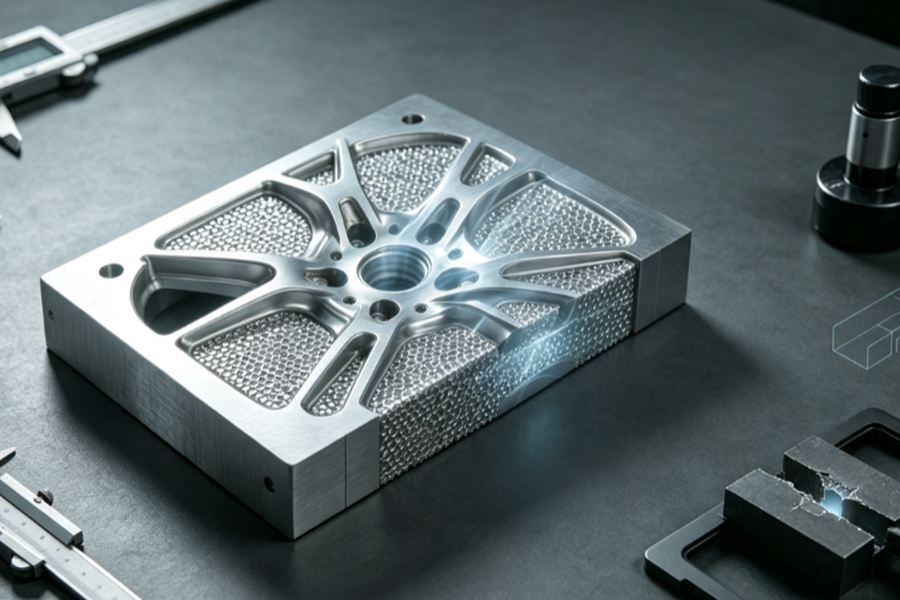
During forging, metal is compressed and shaped rather than poured into a mold. Controlled deformation produces a denser structure and directs material flow around the wheel profile.
Practical advantages:
- Better resistance to crack initiation
- Lower risk of internal shrinkage defects
- Improved impact toughness
- Higher strength at reduced section thickness
- More stable performance under repeated loading
- Better suitability for lightweight wheel designs
Main Factors
Fatigue performance assessment ought to be carried out from a systematic perspective instead of relying merely on individual material parameters.
| Factor | Shorter Life | Longer Life |
| Load | Overload, impact | Rated load |
| Geometry | Sharp transitions | Smooth radii |
| Surface | Scratches, corrosion | Protected finish |
| Heat Treatment | Uneven hardness | Stable properties |
| Machining | Excess removal | Controlled allowance |
| Runout | High runout | Good concentricity |
| Temperature | Overheating | Controlled heat |
| Repair | Welding, repeated straightening | No structural repair |
| Installation | Uneven torque | Correct mounting |
Among these factors, damage location deserves particular attention. A shallow mark in a low-stress area does not carry the same risk as an equally sized defect at a spoke root or bolt hole.
Typical Starting Sites for Fatigue Cracks
Fatigue cracks normally start where stress is concentrated. These areas should receive priority during inspection.
Spoke-to-Rim Transition
The spoke-to-rim connection transfers radial and cornering loads. Abrupt changes in thickness can create local stress concentration.
Potential causes include:
- Insufficient transition radius
- Excessive pocket machining
- Impact deformation
- Surface grinding marks
- Previous straightening
Cracks in this area should normally be treated as structural damage rather than cosmetic damage.
Hub and Spoke Root
The hub area transfers torque and clamping force into the wheel body. Small cracks can grow quickly when braking and acceleration loads alternate frequently.
Inspection should focus on:
- Spoke roots
- Hub windows
- Inner mounting surface
- Center bore transition
- Machined pockets near the hub
Material removal in this area should be strictly controlled during Custom wheel development.
Bolt Holes
Bolt holes experience high local pressure from tightening and repeated load transfer.
Common problems include:
- Elongated holes
- Fretting marks
- Cracks extending from the hole edge
- Damaged seating surfaces
- Incorrect bolt or nut contact
Re-machining a damaged bolt hole may restore its appearance but can change the clamping geometry. For this reason, bolt-hole repair is considerably more restricted than surface refinishing.
Bead Seat and Flange
The bead seat maintains tire sealing and transfers tire forces into the rim. Impact damage may produce bending, local flattening, or cracking.
Minor flange deformation may sometimes be corrected. Cracks, deep material loss, or repeated deformation require a more conservative decision.
Repairable and Non-Repairable Damage
Not every defect requires replacement. At the same time, not every defect should be repaired simply because a workshop can physically remove it.
| Damage | Action | Decision |
| Coating scratch | Refinish | Repair |
| Light corrosion | Clean and inspect | Repair |
| Minor flange bend | Straighten once | Conditional |
| Excessive runout | Measure and review | Conditional |
| Spoke or bolt-hole crack | Remove from service | Replace |
| Bead-seat crack | Remove from service | Replace |
| Deep gouge | Check thickness | Review/Replace |
| Heat or repeated repair damage | Full inspection | Replace preferred |
Rather than general acceptance criteria, these categories provide screening references. Final repair solutions are subject to wheel drawings, material specifications, inspection processes and customer approval demands.
Inspection Methods Before Repair
Visual and Dimensional
Basic checks include:
- Radial runout
- Lateral runout
- Rim width
- Flange profile
- Bolt-hole condition
- Mounting-face flatness
- Center bore size
- Local wall thickness
Through these measurements, engineers can judge whether the defect is discrete or accompanied by large-scale deformation.
Dye Penetrant
Dye penetrant inspection is useful for detecting surface-opening cracks in non-porous materials. It is particularly suitable around spoke roots, bead seats, and machined transitions.
Magnetic Particle
For suitable ferromagnetic steel wheels, magnetic particle inspection can reveal small surface and near-surface discontinuities.
Ultrasonic
Ultrasonic inspection can identify internal defects or crack depth where geometry allows reliable probe contact.
Hardness Testing
Hardness comparison can help identify abnormal thermal exposure, local softening, or inconsistent heat treatment.
Repair vs. Replacement
| Item | Repair | Replacement |
| Cost | USD 80–300 | USD 500–1,500+ |
| Lead Time | 1–3 days | 7–30 days |
| Suitable Damage | Scratches, corrosion, flange bend ≤2 mm | Cracks, major distortion, repeated repairs |
| Fatigue Life | Reduced or uncertain | New-part level |
| Best Choice | Minor, non-structural damage | High-load or safety-critical use |
Workshop cost-minimized solutions may trigger severe subsequent operational risks. Repair economic analysis needs to cover inspection fees, downtime, rebalancing, warranty liabilities and potential secondary equipment damage.
Important Considerations
- Damage Location
A defect in a highly stressed area carries greater risk than the same defect on a decorative surface.
- Remaining Section Thickness
Removing damage by machining is acceptable only when sufficient material remains.
- Repair History
A wheel with repeated straightening, welding, or heavy refinishing has a less predictable fatigue condition.
- Operating Consequence
Passenger transport, high-speed rotation, and heavy lifting require more conservative limits.
- Traceability
Material heat number, forging batch, inspection results, and repair records improve decision quality.
- Replacement Availability
A new forging can retain the original interface while improving local radii, machining allowance, and inspection access.
Repair Guide
| Wheel Condition | Recommended Decision |
| Surface coating damage only | Refinish |
| Light corrosion without section loss | Clean, inspect, and recoat |
| Minor flange bend with no crack | Controlled one-time straightening |
| Runout remains outside tolerance | Replace or engineering review |
| Crack in spoke, hub, or bolt hole | Replace |
| Crack in bead seat or rim section | Replace |
| Fire or severe overheating exposure | Quarantine; replacement preferred |
| Previous structural welding | Restricted use or replacement |
| Multiple previous repairs | Replace |
| Unknown material or repair history | Treat as high risk |
Manufacturers and fleet operators should define repairable zones, prohibited areas, inspection methods, and repair limits in advance, turning wheel repair from workshop judgment into a controlled engineering process with traceability.