Forged cylinder sleeves are essential in high-performance engines and industrial machinery, withstanding extreme pressure, heat, and friction. Engineers need to be aware of their manufacturing tolerances in order to guarantee efficiency, dependability, and adherence to quality requirements.
Understanding Forged Cylinder Sleeves
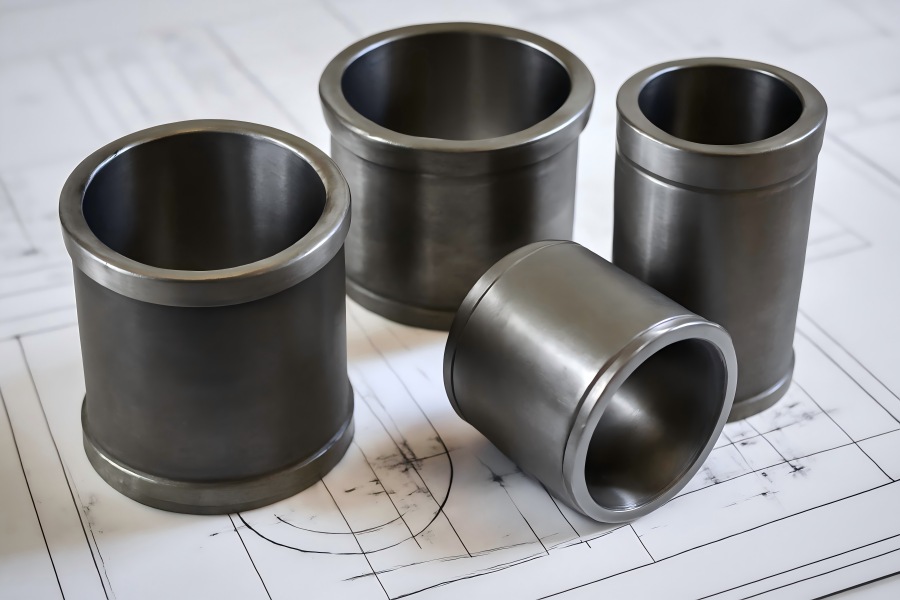
What Is a Cylinder Sleeve?
A hollow cylindrical part called a cylinder sleeve, sometimes referred to as a cylinder liner, is placed into the engine block bore. The piston travels against this surface, which also forms the combustion chamber’s inner wall. Cylinder sleeves offer wear resistance, allow bore repair, and can enhance thermal and mechanical properties.
Why Use Forged Cylinder Sleeves?
Forging enhances the material’s mechanical strength and grain structure. Compared to cast or machined sleeves, forged sleeves offer:
- Higher fatigue strength
- Superior surface integrity
- Improved thermal conductivity
- Better dimensional stability
These advantages are essential in high-performance applications such as motorsport, aviation engines, heavy-duty diesel engines, and industrial compressors.
Key Types of Tolerances in Forged Cylinder Sleeves
Understanding the types of tolerances applied in sleeve manufacturing is critical to achieving reliable engine assembly and performance.
| Tolerance Type | Description |
| Dimensional Tolerance | Permissible variation in sleeve dimensions (OD, ID, length) |
| Geometric Tolerance | Tolerances controlling shape: roundness, straightness, cylindricity, etc. |
| Surface Tolerance | Surface finish (Ra, Rz) values impacting wear and sealing performance |
| Thermal Expansion Tolerance | Dimensional change under heat and its design allowance |
| Concentricity Tolerance | Coaxial alignment between bore and outer diameter |
Dimensional Tolerances and Their Role in Engine Fit
Dimensional tolerances specify allowable variations in sleeve OD, ID, and length, directly affecting fit, performance, and interaction with engine components. Even slight deviations can impact reliability and safety.
Outer Diameter (OD) Tolerances
The sleeve’s outer diameter (OD) determines its interference fit with the block bore, ensuring stability under combustion loads while accommodating thermal expansion.
- Typical press-fit interference: 0.02–0.08 mm
- Design goals: ensure good thermal contact, prevent sleeve rotation or axial movement, and avoid stress concentrations that lead to cracking.
Example:
- Nominal OD: 100.00 mm
- Tolerance: ±0.01 mm
- Acceptable range: 99.99 mm – 100.01 mm
Even such a small range is critical. Deviations outside of tolerance can result in:
- Poor thermal conductivity between the sleeve and the engine block
- Cracks due to excessive press-fit or thermal stress
- Sleeve loosening or rotation under combustion pressure
Proper OD control ensures long-term mechanical stability and thermal efficiency.
Inner Diameter (ID) Tolerances
The inner diameter (ID) of the sleeve defines the piston-to-wall clearance, which is one of the most sensitive dimensions in engine design. If this clearance is too small, it leads to:
- Excessive friction
- Heat build-up
- Risk of piston seizure
If too large, it causes:
- The way the piston rings and cylinder wall rub against one another
- Higher oil consumption
- Piston slap and noise
Typical clearance recommendations:
- Gasoline engines: 0.03–0.06 mm
- Diesel engines: 0.05–0.10 mm (due to higher thermal expansion and loading)
Engineers must consider:
- Material thermal expansion coefficients
- Expected operating temperatures
- Lubrication conditions
- Piston coating and ring material compatibility
ID tolerances often require final honing to achieve the desired accuracy and surface finish.
Length Tolerances
The overall length of the cylinder sleeve determines how it interfaces with other engine components, such as the cylinder head, piston ring travel range, and coolant passages.
Incorrect length can lead to:
- Improper compression ratio
- Incomplete piston ring sealing
- Disruption of the head gasket sealing surface
- Uneven wear on piston rings
- Typical tolerance: ±0.05 mm
This level of precision ensures:
- Proper seating depth within the engine block
- Correct alignment with sealing surfaces
- Reliable and repeatable engine performance across cylinders
In some designs, tighter tolerances may be required to ensure all sleeves maintain a consistent combustion chamber volume, especially in high-performance or multi-cylinder engines.
Geometric Tolerances
Dimensional tolerance alone doesn’t ensure fit. Geometric tolerances control the shape and positional accuracy.
Roundness
Ensures uniform piston ring contact and even pressure distribution. Deviations lead to gas blow-by and ring wear.
Acceptable roundness: ≤0.005 mm for performance engines
Straightness
Affects piston ring sealing along the sleeve’s length. Critical in long-stroke diesel engines.
Typical tolerance: ≤0.01 mm
Cylindricity
Cylindricity combines roundness and straightness for 3D form control. It must be maintained within ±0.01 mm in precision applications.
Concentricity
Crucial for maintaining crankshaft and piston alignment. Misalignment can damage bearings and reduce engine lifespan.
Target concentricity:≤0.015 mm
Surface Finish Tolerances
Surface Roughness
An important factor in engine performance is the inner surface finish, which is determined by metrics like mean peak-to-valley height (Rz) and average roughness (Ra). It directly influences:
- The way the cylinder wall and piston rings rub against one another
- Oil film retention, essential for lubrication and cooling
- Piston ring wear and sealing efficiency over time
Typical Ra values:
- Forged sleeve (as-machined): Ra 0.8–1.6 µm
- Honed finish: Ra 0.3–0.5 µm
A properly finished surface must strike a balance—smooth enough to reduce friction, yet textured enough to retain oil. This balance helps engines last longer, wear down less, and comply with current emission regulations.
Honing and Plateau Finishing
Honing introduces a precise crosshatch pattern on the bore surface, which:
- Facilitates piston ring break-in during early engine operation
- Improves oil retention, especially in vertical running surfaces
- Reduces wear by minimizing high-spot contacts
Thermal Expansion and Heat Tolerances
Forged cylinder sleeves operate under high thermal loads during engine operation. Engineers must carefully account for:
- Coefficient of thermal expansion (CTE) between sleeve and block materials
- Heat soak tolerance during engine warm-up and sustained operation
- Interference fit stability under thermal growth conditions
Typical CTE values:
- Forged steel sleeves: ~11–13 × 10⁻⁶ /°C
- Aluminum alloy blocks: ~22–25 × 10⁻⁶ /°C
This significant mismatch in expansion rates can lead to stress concentrations, potential cracking, or loosening of the sleeve if tolerances are not properly designed. Accurate simulation and material selection are essential to ensure long-term dimensional stability and sealing integrity.
Key Standards and Tolerance Guidelines
Several standards guide cylinder sleeve tolerances:
| Standard | Description |
| ISO 286-1 | Fits and tolerances for engineering components |
| ISO 1101 | Geometric tolerancing |
| DIN ISO 6621 | Internal combustion engine components (piston rings and sleeves) |
| ANSI B46.1 | Surface roughness and finish standard |
| ASTM A536 | Material spec for ductile cast iron sleeves (for comparison) |
Engineers should specify and verify tolerances based on these to ensure compatibility and quality.
Manufacturing Processes Impacting Tolerances
Forging Process
Several parameters influence the final dimensional accuracy of a forged sleeve, including:
- Die accuracy: Precision in die design and maintenance ensures consistent shape and size.
- Material grain flow control: Proper flow improves strength and dimensional stability.
- Flash trimming: Accurate trimming minimizes distortion along parting lines.
Closed-die forging is preferred over open-die methods when tighter dimensional tolerances and repeatability are required.
CNC Machining
After forging, CNC machining refines critical features such as ID, OD, and sleeve length. Modern machining centers use:
- In-process measurement systems for real-time feedback.
- Temperature compensation to counter thermal expansion effects.
- Tool wear compensation for consistent quality over long production runs.
Typical CNC tolerances can reach ±0.01 mm or better, making this step essential for achieving final dimensional control.
Honing
Honing is the final step in bore finishing, correcting minor deviations in roundness, taper, and surface roughness. It also imparts the desired crosshatch pattern to improve oil retention and piston ring seating, contributing to performance and longevity.
Tolerance Stack-Up and Assembly Considerations
Even when individual component tolerances are within specification, their combined effect, known as tolerance stack-up, can lead to unexpected assembly issues or functional failures.
For example:
When the sleeve’s outer diameter tolerance is combined with the engine block’s bore tolerance, the resulting net fit tolerance may deviate from the intended press-fit range. This could result in either excessive interference, causing assembly difficulties or stress cracks, or excessive clearance, leading to sleeve movement or vibration.
To mitigate these risks, engineers should apply statistical tolerancing methods and GD&T (Geometric Dimensioning and Tolerancing) principles. These tools help manage variation across multiple parts and ensure overall assembly performance remains within acceptable limits.
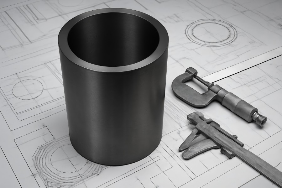
Inspection Methods for Tolerances
Precision inspection is essential to ensure that forged sleeves meet design specifications. Various quality assurance tools are used to verify dimensional and geometric tolerances at different stages of manufacturing.
| Parameter | Inspection Tool |
| OD, ID, Length | Micrometers, Vernier calipers |
| Roundness | Roundness testers |
| Straightness | Dial gauges, laser scanning systems |
| Surface Finish | Profilometers (Ra, Rz) |
| Concentricity | CMM (Coordinate Measuring Machines), rotary tables |
In addition, real-time SPC (Statistical Process Control) is widely used on production lines to monitor variation trends and ensure the process remains within control limits. This helps maintain consistent quality and track capability metrics like Cp and Cpk for continuous improvement.
Common Tolerance Issues and How to Prevent Them
| Problem | Cause | Prevention |
| Sleeve looseness | OD out of tolerance | Tighter control of forging and machining |
| Piston scuffing | ID too tight or rough | Proper honing and surface testing |
| Blow-by | Out-of-round or tapered bore | Final honing + roundness inspection |
| Overheating | Improper interference or thermal mismatch | CTE calculations and press-fit simulation |
| Vibration/misalignment | Concentricity errors | 3D CMM verification |
Tolerance Table for Forged Cylinder Sleeves
| Parameter | Typical Value Range | Target Tolerance | Notes |
| Outer Diameter (OD) | 80 – 150 mm | ±0.01 – 0.02 mm | Dependent on press-fit requirements |
| Inner Diameter (ID) | 70 – 140 mm | ±0.005 – 0.01 mm | Depends on piston clearance |
| Length | 100 – 300 mm | ±0.05 mm | Stroke compatibility |
| Roundness | ≤0.005 mm | ±0.002 – 0.005 mm | Honing corrects post-machining |
| Straightness | ≤0.01 mm | ±0.005 – 0.01 mm | Ensures smooth piston travel |
| Concentricity | ≤0.015 mm | ±0.01 – 0.015 mm | Centerline alignment critical |
| Surface Finish (Ra) | 0.3 – 1.6 µm | As per engine spec | Lower Ra for better wear life |
| CTE (Forged Steel) | ~11–13 x10⁻⁶/°C | Material-specific | Design for differential expansion |
Best Practices for Engineers
Specify Functional Tolerances
Avoid unnecessarily tight tolerances unless functionally required. Define tolerances based on part performance needs to ensure reliability without inflating production costs.
Collaborate Early with Forging Vendors
Engage suppliers during the initial design phase to align tolerances with real manufacturing capabilities and reduce late-stage revisions or scrap.
Use 3D GD&T and CAD Models
Implement 3D GD&T in CAD models to accurately define geometric controls, improve communication, and streamline quality inspection.
Adopt Statistical Tolerancing
Apply statistical methods to manage tolerance stack-up, reduce variability, and increase process yield and design robustness.
Validate Tolerances with Simulation
Use FEA to simulate real operating conditions, helping engineers refine tolerance decisions for both mechanical strength and thermal stability.
Future Trends in Forged Sleeve Tolerancing
AI-Powered Quality Control
In order to improve accuracy and decrease inspection time, machine learning algorithms will make it possible to detect and remedy tolerance deviations in real time.
Intelligent Forging Equipment
Closed-loop systems with sensor feedback will automatically adjust tool paths during forging, ensuring consistent dimensional control throughout the process.
Advanced Materials
The use of high-performance alloys like forged titanium and Inconel is expanding, especially in aerospace, where tighter tolerances are critical under extreme conditions.
Digital Twins
Virtual engine models will simulate tolerance behavior before production, allowing engineers to validate designs, anticipate issues, and optimize manufacturing parameters early.