
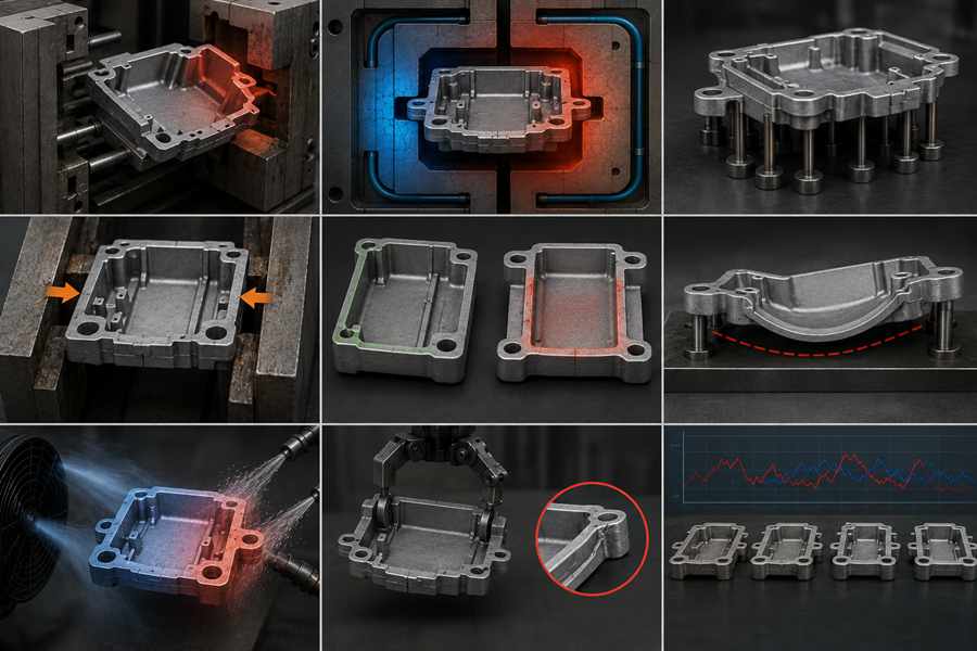
Die-cast part distortion may result from early ejection, uneven die cooling, poor ejector layout, excessive release force, irregular wall thickness, weak support, uncontrolled air or water cooling, improper transfer, and unstable production cycles.
1. Premature Ejection
In die casting, premature ejection occurs when the component leaves the die before developing enough strength. Its outer surface may appear solid, while thicker internal areas remain hot and vulnerable to deformation.
Causes:
- Insufficient cooling time:A shortened holding period may leave the part unable to withstand ejector pressure.
- Elevated ejection temperature:Excessive melt or die temperature can delay complete solidification.
- Improper cycle settings:Cooling time may be calculated from average walls rather than the slowest-cooling section.
Mitigation Strategies:
- Increase in-die cooling:Set the holding time according to thick bosses, flanges, and heavy junctions.
- Track release temperature:Use thermal sensors or imaging equipment instead of depending only on cycle duration.
- Measure after stabilization:Compare dimensions at ejection with readings taken after the casting has fully cooled.
2. Uneven Die Cooling
Uneven die cooling occurs when separate cavity regions lose heat at different rates. Cooler sections become rigid earlier, while hotter zones continue contracting and pull the component away from its intended shape.
Causes:
- Imbalanced cooling channels:Some passages may sit too near the cavity, while others remain too far from hot areas.
- Limited water circulation:Corrosion, deposits, or internal blockage can weaken heat removal in certain zones.
- Concentrated thermal load:Gates, deep ribs, and thick bosses often retain heat longer than nearby walls.
Mitigation Strategies:
- Optimize channel distribution:Arrange cooling passages around actual hot spots instead of using equal spacing alone.
- Monitor water performance:Record flow, pressure, inlet temperature, and outlet temperature during production.
- Service cooling circuits:Remove buildup before restricted circulation causes repeated dimensional variation.
3. Improper Ejector Pin Arrangement
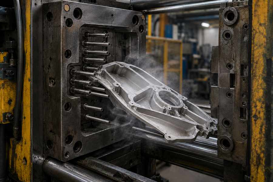
Ejector pins push the finished casting away from the die cavity. When their quantity or arrangement is unsuitable, release pressure may bend thin walls and poorly supported features.
Causes:
- Insufficient pin quantity:Too few pins force each contact point to carry a larger share of the release load.
- Weak contact areas:Pins placed beneath broad flat walls may leave dents or create local bending.
- Inconsistent pin travel:Damaged pins, worn plates, or unequal lengths may cause one side to release earlier.
Mitigation Strategies:
- Spread the pin pattern:Distribute ejection pressure across the component instead of loading one limited area.
- Select rigid locations:Position pins close to ribs, bosses, gates, and reinforced wall intersections.
- Verify synchronized movement:Check that every pin advances evenly during mold trials and routine production.
4. Excessive Ejection Force
Excessive ejection force is needed when the casting adheres too strongly to the cavity. Greater pressure may free the component, but it can also move walls, bosses, and edges out of position.
Causes:
- Limited draft angle:Deep or nearly vertical surfaces create more resistance during part release.
- Casting adhesion:Rough cavity areas, metal buildup, or localized overheating may hold the part inside the die.
- Uneven lubricant application:Incomplete release-agent coverage increases friction in selected regions.
Mitigation Strategies:
- Adjust draft design:Provide enough taper for reliable removal without creating excessive machining allowance.
- Restore die surfaces:Polish rough zones and clean adhered metal before raising ejector pressure.
- Control lubricant spraying:Maintain consistent spray location, quantity, and timing throughout each production batch.
5. Uneven Wall Thickness
Sections with different thicknesses lose heat and shrink at different speeds. Heavy areas stay hot longer and may continue moving after adjacent thin walls have already become rigid.
Causes:
- Overly thick bosses:Heavy mounting features create concentrated heat zones within the casting.
- Sudden section transitions:Sharp changes between thin and thick walls interrupt balanced solidification.
- Asymmetrical part geometry:Large features on one side may pull the component away from its designed position.
Mitigation Strategies:
- Hollow out heavy areas:Remove unnecessary metal from oversized bosses and thick wall intersections.
- Create smoother transitions:Use suitable radii and gradual changes to improve temperature distribution.
- Balance reinforcing features:Arrange ribs and mounting sections so opposing areas cool at similar rates.
6. Inadequate Post-Ejection Support
A hot casting may satisfy tolerance when released but deform while cooling on a table or conveyor. Wide panels, open frames, and long parts are particularly likely to sag.
Causes:
- Long unsupported sections:Extended spans may bend under their own weight before developing enough rigidity.
- Irregular contact surfaces:Gates, runners, or raised bosses can keep one side above the cooling fixture.
- Premature part stacking:Upper components may press lower castings into a permanently distorted shape.
Mitigation Strategies:
- Install profile-matched fixtures:Hold important surfaces with supports shaped around the casting geometry.
- Standardize cooling orientation:Place every component in the same stable position after removal.
- Delay stacking operations:Keep castings separated until they reach a temperature suitable for normal handling.
7. Uncontrolled Air or Water Cooling
External cooling can reduce cycle time, but uneven heat extraction introduces thermal stress. Strong airflow or concentrated water spray may make one region contract much faster than another.
Causes:
- Directional fan cooling:Airflow may lower the temperature of the nearest surface faster than the opposite side.
- Incomplete spray coverage:Partial water contact creates sudden temperature differences across the component.
- Variable conveyor operation:Changes in orientation or travel speed alter the cooling received by each casting.
Mitigation Strategies:
- Distribute airflow evenly:Arrange fans so both sides of the component receive similar cooling.
- Regulate water spraying:Set consistent water temperature, pressure, duration, and coverage.
- Stabilize conveyor movement:Keep part position, spacing, and transfer speed repeatable during each cycle.
8. Poor Part Removal and Transfer
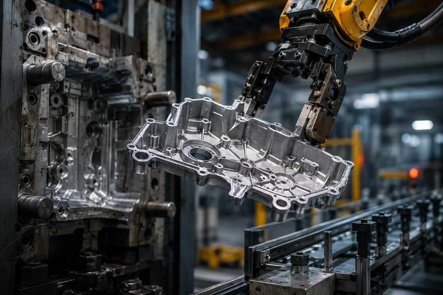
Castings may be damaged while moving from the open die to the trimming or cooling station. Grippers, impacts, and unstable placement can produce deformation that resembles a molding defect.
Causes:
- Unsuitable gripping locations:Flexible walls may be compressed instead of holding the part through rigid features.
- High clamping pressure:Excessive gripping force can permanently shift thin or unsupported sections.
- Transfer impact:Long drops or contact with neighboring castings may bend edges and corners.
Mitigation Strategies:
- Handle reinforced features:Use gates, ribs, bosses, or rigid edges as the main gripping positions.
- Reduce gripping pressure:Apply only the force needed to move the part securely.
- Minimize transfer shock:Use guided placement, shorter drop distances, and controlled conveyor spacing.
9. Unstable Process Cycles
An unstable production cycle changes the die’s thermal condition between shots. Even well-designed tooling can produce inconsistent dimensions when cooling and ejection settings vary repeatedly.
Causes:
- Unexpected machine stops:The die loses heat during downtime and performs differently after production resumes.
- Changing spray duration:Variations in lubricant and cooling time alter cavity temperature.
- Unstable molten-metal temperature:Different pouring conditions affect solidification speed and release behavior.
- Variable cooling-water supply:Fluctuating pressure or temperature disturbs the established thermal balance.
Mitigation Strategies:
- Fix operating parameters:Standardize injection, spraying, cooling, ejection, and transfer times.
- Isolate startup components:Separate the first castings until the tool reaches its regular working temperature.
- Connect thermal and dimensional data:Compare cavity, ejection, and cooling-water temperatures with inspection results.
- Approve fully cooled parts:Accept production samples only after their dimensions have become stable.