
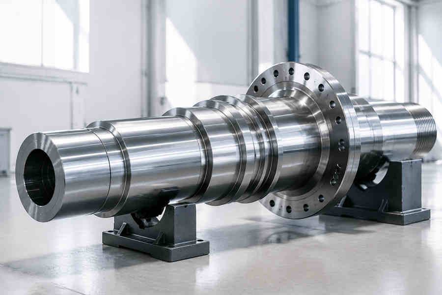
A large forged shaft can show perfect geometry after rough machining, yet warp during heat-treatment. Minor distortion is simple to fix on short shafts, but parts several meters long leave very little room for error.
Even subtle bending extends grinding work, eats into journal stock and shifts bearing-seat runout. Custom forged shafts require stability planning across forging, heat-treatment and finishing, not just final inspection.
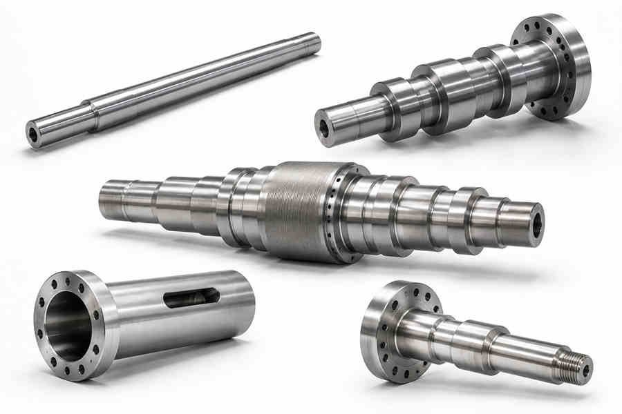
Large forged shafts may include:
- Straight shafts
- Stepped shafts
- Flanged shafts
- Hollow shafts
- Rotor shafts
- Generator shafts
- Transmission shafts
Where Dimensional Changes Usually Appear
| Shaft Area | Possible Change | Production Effect |
| Long shaft body | Bending | Extra straightening |
| Bearing journal | Diameter change | Additional grinding |
| Large shoulder | Local distortion | Alignment correction |
| Flanged end | Face movement | Coupling issues |
| Internal bore | Concentricity change | Extra boring |
| Stepped section | Runout variation | Re-machining |
Residual Stress Left From Forging
Key factor: Internal stress distribution
Forging changes the shaft through heavy plastic deformation. Once the component cools, the outside may look stable, but internal stresses can still remain.
Several operations can contribute to this condition:
- Upsetting
- Drawing
- Local forming
- Straightening
- Repeated diameter transitions
When the shaft enters heat treatment, some of these stresses are released or redistributed.
The dimensional result may appear as:
- Shaft bending:the original centerline moves slightly.
- Journal runout:previously aligned surfaces no longer rotate around exactly the same axis.
- Shoulder movement:axial dimensions shift around stepped sections.
- Diameter variation:additional stock has to be removed during finishing.
Forging Uniformity Matters
If the forged blank is uneven, one side may require significantly more rough machining than the other. Material removal then changes the stress balance again before heat treatment starts.
In practical terms:
- Uneven forging stock leads to uneven material removal.
- Uneven material removal changes internal stress distribution.
- Greater stress imbalance increases the chance of post-treatment movement.
For repeat Custom shaft orders, controlling this condition at the forging stage is usually more efficient than correcting the same distortion during every finishing cycle.
Different Shaft Sections Heat at Different Speeds
Key factor: Cross-sectional variation
A single shaft may contain a large coupling end, narrow bearing journals, several shoulders, and a flange. They enter the same furnace, but their thermal response is different.
Typical differences include:
- Thick sections heat through more slowly.
- Narrow journals respond faster.
- Large flanges retain more heat.
- Internal bores change the way heat moves through the section.
- Repeated diameter transitions create several thermal zones along one shaft.
Geometry and Dimensional Risk
| Shaft Type | Stability Concern | Area to Watch |
| Straight shaft | Overall bending | Full length |
| Stepped shaft | Uneven movement | Shoulders |
| Flanged shaft | Local distortion | Flange transition |
| Hollow shaft | Bore movement | Internal diameter |
| Rotor shaft | Runout | Bearing journals |
| Eccentric shaft | Axis relationship | Offset sections |
Shoulder Areas Need More Attention
A heavy shoulder beside a small journal creates a clear mass difference. Under heating-and-cooling conditions, the response rates of the two sections are not perfectly matched.
This can affect functional areas such as:
- Bearing seats
- Seal positions
- Coupling sections
- Assembly shoulders
- Precision journal transitions
Heating Uniformity Becomes Harder on Large Shafts
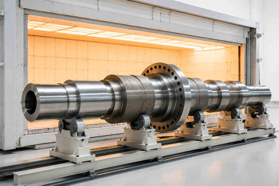
Key factor: Temperature consistency
A furnace reaching its target temperature does not mean every point inside a large forged shaft has reached that temperature at the same time.
For large shafts, the heat-treatment plan should consider more than the nominal furnace temperature:
- Maximum section diameter
- Total component weight
- Flange thickness
- Number of stepped sections
- Heating rate
- Holding time
- Shaft position inside the furnace
A 5,000 kg shaft and a much lighter shaft may use the same steel grade, but their thermal behavior is clearly not identical.
Furnace Support Can Affect Straightness
Long forged shafts are already heavy at room temperature. At elevated temperatures, support position becomes even more important.
Poor support may cause:
- Sagging between support points
- Local bending
- Increased shaft runout
- Additional straightening work
- Uneven loading around stepped areas
A heat-treatment cycle may be technically correct while the shaft still leaves the furnace with a straightness problem.
For large Custom forged shafts, furnace loading should therefore be treated as part of dimensional control rather than simple handling.
Cooling Can Create More Distortion Than Heating
Key factor: Uneven contraction
Heating causes expansion. Cooling brings the shaft back toward its original size, but every section does not contract at the same speed.
Typical differences include:
- Thin journals cool faster than heavy sections.
- Large flanges remain hot longer.
- Exposed shaft ends can react differently from the center.
- Hollow sections may cool differently from solid sections.
- Stepped regions create local cooling differences.
The dimensional effects may include:
- Bending
- Increased runout
- Diameter movement
- Shoulder displacement
- Flange distortion
- Bore concentricity change
Some dimensional movement after heat treatment is not unusual on a large forged component. The more important issue is whether enough machining allowance remains to recover the final geometry.
Machining Allowance Should Follow Risk
| Feature | Allowance Priority | Main Reason |
| Bearing journal | High | Diameter and runout |
| Seal surface | High | Fit and finish |
| Large shoulder | Medium–High | Local movement |
| Coupling end | High | Axis alignment |
| General shaft body | Medium | Usually less critical |
| Internal bore | High | Concentricity |
Machining Sequence Can Improve or Reduce Stability
Key factor: Timing of material removal
Large forged shafts are usually machined in stages:
- Forging
- Rough machining
- Heat treatment
- Straightness check
- Semi-finish machining
- Final grinding and inspection
Critical dimensions should not be finished too early. Heat treatment and heavy rough machining can still release stress and change shaft geometry.
Precision operations are better kept for later stages, especially for:
- Bearing journals
- Seal surfaces
- Splines
- Coupling faces
- Precision bores
Material Grade Changes the Shaft’s Response
Key factor: Material and heat-treatment combination
A range of engineering materials including carbon steel, alloy steel, stainless steel and nickel-base alloys are available for fabricating large forged shafts.
Common shaft materials can include:
- 1045
- 4140
- 4340
- 304
- 316
Changing the material can affect more than mechanical properties.
It may also change:
- Heat-treatment temperature
- Holding requirements
- Cooling conditions
- Final hardness
- Machining difficulty
- Straightening response
- Available finishing allowance
What Should Be Checked After Heat Treatment?
Waiting until final machining to discover shaft movement is expensive. Post-heat-treatment inspection should identify dimensional changes while enough stock remains for correction.
| Inspection Item | What It Checks | Why It Matters |
| Straightness | Overall shaft bend | Determines straightening need |
| Journal runout | Axis change | Protects bearing alignment |
| Diameter | Local movement | Confirms remaining stock |
| Shoulder position | Axial dimensional change | Affects assembly |
| Flange face | End distortion | Important for coupling |
| Bore concentricity | Internal movement | Prevents late correction |
Useful post-treatment checks include:
- Measure overall shaft straightness.
- Check runout at major journals.
- Recheck critical diameters.
- Measure axial shoulder positions.
- Inspect flange-face distortion.
- Confirm bore concentricity where required.
Dimensional Stability Is Not Only a Heat-Treatment Issue
It is possible that the actual chain was initiated at a much earlier stage.
- Uneven forging creates uneven stock.
- Uneven stock requires heavier machining on one side.
- Heavy material removal changes the stress balance.
- Heat treatment releases more internal stress.
- Poor furnace support adds another source of movement.
- Uneven cooling makes the final distortion visible.
By final grinding, the manufacturer may simply be correcting the accumulated effect of several earlier stages. For Custom forged shafts, it is more useful to connect the complete route:
Forging → Stock Distribution → Rough Machining → Heat Treatment → Cooling → Inspection → Straightening → Final Machining
Which Factor Has the Biggest Influence?
Each shaft configuration carries its own set of governing limiting factors, where certain variables rise to become performance-determining priorities.
Long slender shafts
Furnace support, baseline straightness, and cooling uniformity sit at the forefront of process risk. These elements outweigh other considerations and call for top-tier attention throughout manufacturing.
Heavy stepped shafts
Section thickness, shoulder transition geometry, and cooling disparity dominate quality outcomes. Their effects are amplified for bulky stepped geometries and must be weighted more heavily in process design.
Large alloy-steel rotor shafts
Dimensional planning is held hostage by three key drivers: heat-treatment sequence, material thermal response, and journal runout. These factors exercise overriding control over final dimensional results.
Hollow shafts
Manufacturing success hinges on bore movement, wall-thickness variation, and internal concentricity. Such inner-profile characteristics constitute the principal pain points for hollow-type shaft production.
Flanged shafts
Particular vigilance is required for flange distortion, shaft-to-flange transition zones, and face alignment. These high-risk features demand enhanced inspection rigor to mitigate part rejection.
Stability for large forged shafts hinges on forging-induced stress, part geometry, heating-cooling cycles, machining order and material traits. All these need joint evaluation before locking in your final dimensional specs.
With custom forged shafts, leave sufficient stock during rough machining. Check straightness, runout and key journal surfaces post-heat-treatment, ahead of final grinding and precision finishing.