Gears transmit motion, torque, and speed in mechanical systems, affecting performance, durability, and noise. Involute, cycloidal, and bevel gears each have different advantages. Proper selection based on load, precision, and cost is essential to avoid wear, inefficiency, vibration, and potential system failure.
What Are Gear Tooth Profiles?
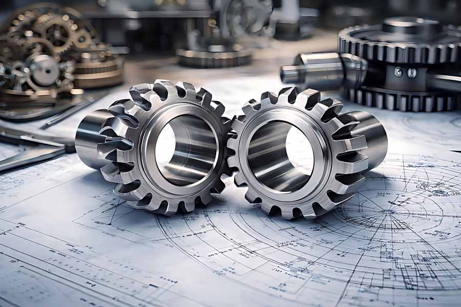
At the heart of every gear lies its tooth profile, the shape of the gear teeth that come into contact during operation. This seemingly simple geometric feature has a profound impact on how gears perform.
When two gears mesh, their tooth profiles determine how force is transmitted. Ideally, the contact between teeth should be smooth and continuous, minimizing friction and wear while maximizing efficiency. However, different profiles achieve this in different ways.
Key Functions of Tooth Profiles
- Motion transmission: Ensures consistent transfer of rotational movement
- Load distribution: Spreads force across multiple teeth to reduce stress
- Efficiency optimization: Minimizes energy loss during operation
- Noise and vibration control: Reduces impact and irregular motion
Why Tooth Profile Matters
A well-designed tooth profile can:
- Extend gear lifespan
- Reduce maintenance costs
- Improve system reliability
- Enhance operational efficiency
Conversely, an unsuitable profile may result in uneven wear, excessive noise, and reduced performance.
What Is an Involute Gear?
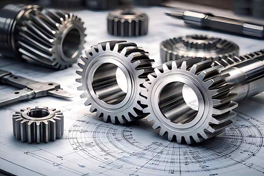
An involute gear uses a tooth profile based on an involute curve, formed by unwinding a taut string from a base circle. This shape keeps the line of action between meshing teeth constant, ensuring smooth and consistent motion.
Involute gears are widely used in modern engineering because they combine good performance, easy manufacturing, and cost efficiency.
Advantages
One of the primary advantages of involute gears is their robustness in real-world conditions. Unlike more sensitive gear types, involute gears can tolerate minor misalignment without significant performance degradation.
Another major benefit is ease of manufacturing. The involute profile can be produced using standard gear-cutting tools such as hobbing and shaping machines. This reduces production costs and enables large-scale manufacturing.
Involute gears also provide excellent efficiency, especially in high-speed applications. Their smooth engagement reduces vibration and ensures consistent torque transmission.
Limitations
Despite their widespread use, involute gears are not without drawbacks. The most notable limitation is the presence of sliding contact between gear teeth. While part of the motion involves rolling, a significant portion involves sliding, which leads to:
- Increased friction
- Heat generation
- Gradual wear over time
Additionally, involute gears may not perform optimally in ultra-low-speed or high-precision applications where minimal backlash is required.
Typical Applications
- Automotive transmissions
- Industrial gearboxes
- Heavy machinery
- Pumps, compressors, and conveyors
What Is a Cycloidal Gear?
Cycloidal gears use a tooth profile generated by a rolling circle, creating a cycloidal curve. Unlike involute gears, cycloidal gears rely more heavily on rolling contact, reducing friction between mating surfaces.
Advantages
The most significant advantage of cycloidal gears is their low wear rate. Because rolling contact dominates, there is less friction between teeth, which results in:
- Longer service life
- Reduced lubrication requirements
- Lower maintenance costs
Cycloidal gears also offer high precision, making them ideal for applications where accurate positioning is critical.
Another important advantage is their capability to withstand shock loads. The distribution of force across multiple contact points allows cycloidal gears to absorb impacts more effectively than involute gears.
Limitations
Cycloidal gears are more complex to design and manufacture. This complexity leads to:
- Higher production costs
- Limited standardization
- Greater sensitivity to alignment errors
Even small deviations in installation can affect performance, making them less forgiving than involute gears.
Typical Applications
- Precision instruments (clocks, watches)
- Robotics and automation systems
- Cycloidal reducers
- Medical and laboratory equipment
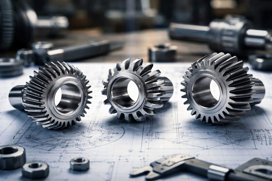
What Is a Straight-Tooth Bevel Gear?
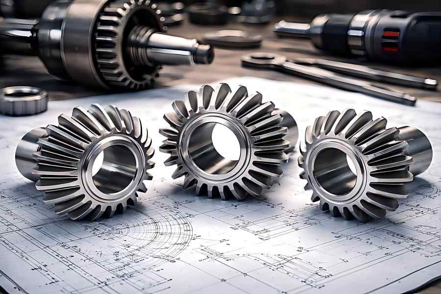
Straight-tooth bevel gears are conical gears designed to transmit motion between intersecting shafts, typically at a 90-degree angle. Their teeth are straight and radiate outward along the surface of a cone.
Advantages
Straight-tooth bevel gears are valued for their simplicity and cost-effectiveness. Their relatively simple design also makes them easy to manufacture, which makes them a practical choice for many mechanical systems.
They also provide reliable performance in moderate-speed applications and are capable of handling reasonable loads without complex engineering.
Limitations
The main drawback of straight-tooth bevel gears is their noise and vibration, especially at higher speeds. Because the teeth engage abruptly, they generate impact forces that can lead to:
- Increased noise levels
- Higher wear rates
- Reduced efficiency
They are also less suitable for high-speed or high-precision applications compared to other gear types.
Typical Applications
- Automotive differentials
- Agricultural machinery
- Power tools
- Right-angle drive systems
Key Differences Comparison
| Feature | Involute Gear | Cycloidal Gear | Straight-Tooth Bevel Gear |
| Tooth Profile Geometry | Involute curve | Cycloidal curve | Straight teeth on مخروط surface |
| Shaft Configuration | Parallel shafts | Parallel or eccentric systems | Intersecting shafts (usually 90°) |
| Contact Type | Sliding + rolling contact | Mostly rolling contact | Intermittent line contact |
| Transmission Efficiency | High (95%–98%) | Moderate–high (90%–95%) | Moderate (90%–96%) |
| Load Capacity | High, suitable for heavy-duty use | Moderate, good for shock loads | Moderate, depends on size/design |
| Noise & Vibration | Low, smooth operation | Very low, minimal vibration | Higher, especially at high speeds |
| Wear & Service Life | Moderate wear over time | Low wear, long lifespan | Higher wear under high-speed use |
| Manufacturing Complexity | Low, easy to mass-produce | High, requires precision machining | Moderate, simpler than spiral bevel |
| Alignment Sensitivity | Low, tolerant to misalignment | High, requires precise alignment | Moderate sensitivity |
| Cost (Initial Investment) | Low to moderate | High (30–60% more) | Low (10–25% cheaper than involute) |
Performance Comparison by Application Scenario
High-Speed Systems
Involute gears are typically preferred for high-speed applications due to smooth meshing, stable transmission, and high efficiency in continuous operation.
Their standardized design, good load distribution, and tolerance to slight center distance variations make them reliable for automotive, industrial, and high-speed power transmission systems.
Precision and Low-Speed Systems
Cycloidal gears are well-suited for precision and low-speed applications because rolling contact reduces friction, minimizes wear, and enables accurate motion control.
They are widely used in robotics, indexing systems, and precision reducers where smooth operation, low backlash, and long-term positioning accuracy are essential.
Right-Angle Power Transmission
Straight-tooth bevel gears are widely applied in right-angle power transmission between intersecting shafts, usually arranged at 90 degrees.
Although they may generate more noise and vibration at higher speeds, they remain a cost-effective and reliable solution for moderate-speed machinery, agricultural equipment, and basic mechanical drives.
Cost vs Performance Trade-Off
Selecting the right gear type means balancing upfront cost with long-term performance, efficiency, and maintenance needs.
- Involute gears are usually the most cost-effective overall, with production costs often 20–40% lower than cycloidal gears. Their transmission efficiency can reach 95%–98%, making them a strong choice for general industrial applications.
- Cycloidal gears typically cost 30–60% more upfront because of their complex design and manufacturing process. However, their lower friction can extend service life by 2–3 times and reduce maintenance costs in precision systems.
- Straight-tooth bevel gears are often 10–25% cheaper than involute gear systems in similar sizes. Their efficiency is usually around 90%–96%, but higher vibration may increase maintenance in continuous-duty use.
How to Select the Suitable Gear for Your Project?
Selecting the right gear type is essential for performance, reliability, and cost, requiring evaluation of multiple technical and practical factors.
Key Selection Factors
Before making a decision, consider the following core parameters:
- Load Requirements
Determine the torque and load the gear must handle, including peak and shock loads. Involute gears are ideal for high loads, while cycloidal gears perform better under fluctuating or impact conditions. - Operating Speed
High-speed systems benefit from involute gears due to their smooth engagement and efficiency. For low-speed, high-precision motion, cycloidal gears are often the better choice. - Precision and Backlash
If your application requires accurate positioning and minimal backlash (such as robotics or automation), cycloidal gears provide superior control compared to other types. - Shaft Configuration
The spatial arrangement of shafts is crucial. Parallel shafts typically use involute gears, while intersecting shafts (e.g., 90° layouts) require straight-tooth bevel gears. - Noise and Vibration Constraints
In environments where quiet operation is important, cycloidal gears offer the lowest noise levels, while straight-tooth bevel gears may generate more vibration at higher speeds. - Installation and Alignment Tolerance
Involute gears are more forgiving when it comes to slight misalignment or center distance variation. Cycloidal gears, on the other hand, require precise installation. - Budget and Cost Considerations
Evaluate both initial cost and lifecycle cost. Lower upfront cost does not always mean lower total cost over time.
Step-by-Step Decision Guide
To simplify the selection process, follow this practical workflow:
Step 1: Define Motion Requirements
Identify whether your system requires parallel shaft transmission, intersecting shafts, or a change in motion direction. This step alone may narrow your options significantly.
Step 2: Analyze Load and Speed Conditions
Evaluate operating speed (RPM) and torque levels. High-speed, continuous systems typically favor involute gears, while low-speed, high-load precision systems may benefit from cycloidal designs.
Step 3: Determine Precision Needs
If your application involves positioning, indexing, or robotics, prioritize low backlash and high accuracy—making cycloidal gears a strong candidate.
Step 4: Consider Environmental Factors
Examine factors including vibration, moisture, dust, and temperature at work. Harsh environments may require more durable and stable gear types.
Step 5: Evaluate Cost vs Performance
Compare initial investment with expected maintenance, efficiency, and service life. Long-term savings are frequently possible with a little greater initial cost.
Step 6: Match Gear Type to Application
- Choose involute gears for general-purpose, high-speed, and cost-sensitive systems
- Choose cycloidal gears for precision, low-wear, and high-accuracy applications
- Choose straight-tooth bevel gears for simple right-angle power transmission